TRENDnet TPE-80WS User Manual
Hide thumbs
Also See for TPE-80WS:
- Quick installation manual (9 pages) ,
- Specifications (2 pages) ,
- Quick installation manual (10 pages)
Table of Contents
Advertisement
Advertisement
Table of Contents

Related Manuals for TRENDnet TPE-80WS


Summary of Contents for TRENDnet TPE-80WS
-
Page 2: Table Of Contents
TABLE OF CONTENT 1.0 I ............................3 NTRODUCTION 1.1 M ............................3 EATURES 1.2 S ........................5 TART TO ANAGE WITCH 2.0 W ............................6 EB MANAGEMENT 2.1 C ............................7 ONFIGURATIONS 2.1.1.1 S ........................... 7 YSTEM INFORMATION 2.1.1.2 DHCP ..............................8 2.1.1.3 HTTP ...................... -
Page 3: Introduction
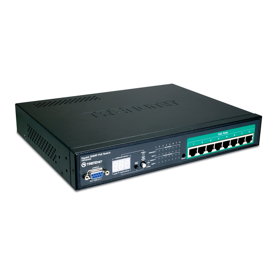
1.0 Introduction TPE-80WS Web Smart PoE Switch is a high performance web-smart switch that provides up to 8 10/100/1000Mbps copper Ethernet ports, this device provides a great flexibility for nowadays variety of network application but at lower cost. User doesn’t have to learn many sophisticated... - Page 4 Port trunk with fail-over capability Support flow control for both full/half duplex operations Support Multicast storm, Broadcast Storm control as well as Flooding Control Support port mirroring LED display for each port to show link and activity status Desktop and optional Rack mountable kit Reset to default “...
-
Page 5: Start To Manage This Switch
1.2 Start to Manage This Switch Either way user may start to manage this switch, web mode through Ethernet port or terminal mode through RS232 port. 1,2,1 Web mode default setting are: Default IP Address: 192.168.223.100 Default IP mask: 255.255.255.0 Default gateway: 192.168.223.254 Default Password: admin 1.2.2 Terminal mode default setting are: baud rate: 115,200, attribute: 8, None, 1, None... -
Page 6: Web Management
2.0 Web management After login is successfully validated, the switch’s home page will show up. The left part on the page provides the function menus, while the right part provides the individual configuration value or system parameters value. Functions are divided into three categories, they are Configuration, Monitoring and Maintenance;... -
Page 7: Configurations
2.1 Configurations 2.1.1.1 System information The system diagram shows every common system information, they are H/W, F/W version, MAC address, IP address, subnet mask, IP gateway, default VLAN value of management port, name, password, timeout value, and SNMP communities…etc. Once user finish the setting, he must press the “... -
Page 8: Dhcp
2.1.1.2 DHCP The default DHCP is off, so Default IP or user defined IP is used when this machine is turning-ON, but if this switch needs an IP assigned from DHCP server, user may click the square field and then press “ Apply “ to get an IP which will be assigned by DCHP server “. User must be aware that if he enable DHCP from web page, and if the DHCP server is working, then after enable DHCP, he will lose contact of web page, because the IP address has been changed. -
Page 9: Ports
2.1.2 Ports Port status page always shows current port status of all 8 ports. User can set link mode, enable or disable flow control and jumbo frame, however, be noticed that the jumbo frame is global setting, it can’t be set on individual port but on all ports at a time. A default diagram is shown below, Port Configuration Port Link Status... -
Page 10: Port-Based Vlan
2.1.3 Port-based VLAN Port-based VLAN is a kind of VLAN which is a group of ports marked as a kind by group ID, different VLAN ( different ID ) can’t communicate to each other. Before the setting, user must be aware of that there is a default Port-based VLAN, his group ID is 1, so, if user wants to set another new port-based VLAN, better set another group ID rather than 1. - Page 11 Port-based VLAN (User Group) Configuration Port-based VLAN Group (User Group) Table Member Port No. Group ID Add/Edit a VLAN (User) Group Member Port Group ID Refresh Delete Apply...
-
Page 12: Tag-Based Vlan
2.1.4 Tag-based VLAN Tag-based VLAN is another kind of VLAN which is a group of ports marked as same kind by assigning a tag-value on each port, same as port-based VLAN, different VLAN ( different ID ) can’t communicate to each other, and before the setting, there is a default tag-based VLAN, which ID is 1 ( VLAN ID=1 ), so, if he wants to set another new tag-based VLAN, better set another VLAN ID rather than 1 ( tag-base VALN ID ranged from 1 ~ 4094 ). - Page 13 advanced tag-VLAN application, here below are explanation when entering the “ Port Config “, they are: 1. VLAN Aware mode: Enable - Strip VLAN tag from received frame, and insert VLAN tag in transmitted frame except ingress frames which tag VID = PVID Disable –...
-
Page 14: Port Trunking
Tagged Only Apply Cancel 2.1.5 Port Trunking A default diagram is shown below, and up to 4 groups are provided Port Trunking (Aggregation) Configuration Group\Port Normal Group 1 Group 2 Group 3 Group 4 Apply Refresh Choose and click the trunk ports you want to group, for example, choose port 1, port 2 into group 1, then press “Apply”, after execution, diagram will shown below Port Trunking (Aggregation) Configuration Group\Port... -
Page 15: Port Mirroring
2.1.6 Port Mirroring A default diagram is shown below, Port Mirroring Configuration Mirror Port Port Mirror Source Apply Refresh Choose and click the ports you want to monitor, for example, choose port 2 To be monitored, then press “Apply”, after execution, diagram will shown below Port Mirroring Configuration Mirror Port Port... -
Page 16: Quality Of Service
2.1.7 Quality of Service A default diagram is shown below, Quality of Service (QoS) Configuration Choose the priority level for the port you want to set; then same priority will get the same priority service. -
Page 17: Storm Control
2.1.8 Storm Control A default diagram is shown below, Storm Control Configuration Storm Control Number of frames per second No Limit Broadcast Rate No Limit Multicast Rate No Limit Flooded Unicast Rate Apply Refresh Choose and click type of storm you want to control, for example, choose Broadcast storm with 3,964 frames per second as upper limit, once the Broadcast frame rate higher than 3,964 frame per second, this port will be disabled. -
Page 18: Lacp
2.1.9 LACP Different from the static port trunking, LACP provides another way to dynamically aggregate port to a group (trunk) according to IEEE 802.3ad. A default diagram is shown below, LACP Port Configuration Port Protocol Enabled Key Value auto auto auto auto auto... -
Page 20: Rstp
2.1.10 RSTP The Spanning-Tree Protocol (STP) is IEEE 802.1d standardized method for avoiding loops in switched networks. Enable STP to ensure that only one path at a time is active between any two nodes on the network. The Rapid-Spanning-Tree-Protocol (RSTP) is a more advanced protocol than STP according to IEEE 802.1w standard. - Page 21 Use the following parameters in the webpage to configure RSTP function: System Configuration System Priority – A value to identify the root bridge. The bridge with lowest value has the highest priority and is selected as the root. 16 numbers are provided in this field from 0 to 61140 in increments of 4096.
-
Page 22: Igmp
2.1.11 IGMP The Internet Group Management Protocol (IGMP) is an internal protocol of the Internet Protocol (IP) suite. IGMP can manage the multicast traffic if the members (switches, router or other network devices) of group support IGMP. This switch provides IGMP snooping feature to detect IGMP queries, report packets and manage the IP multicast traffic through the switch. - Page 23 2.1.12 802.1x A default diagram is shown below, user must contact the manager of RADIUS server, and then get IP, UDP port number and secret to operate 802.1X. 802.1X Configuration Disabled Mode 0.0.0.0 RADIUS IP 1812 RADIUS UDP Port RADIUS Secret Port Admin Mode Port State...
-
Page 24: P Oestatus And Command Operation
2.1.13 PoE status and command operation Some status definition described below before you read or execute the command, Non-PD, this means there is an ethernet device but not PD device is loaded No Load: there is not any PD device being loaded to that port, but non-PD may be Loaded: a PD device is being loaded, class level and allocated power is shown PD Error:... -
Page 25: Monitoring
2.2 Monitoring 2.2.1. Port Statistics Choose and click command manual, after execution, diagram will shown below, user can clear counter or refresh as will Statistics Overview for all ports Port Tx Bytes Tx Frames Rx Bytes Rx Frames Tx Errors Rx Errors 4837 1122... -
Page 26: Detailed Port Statistic
2.2.2 Detailed Port Statistic Choose and click command manual, more detailed count will be displayed like below, user can analyze frame per frame size, byte and error types. Statistics for Port 2 Port 1 Port 2 Port 3 Port 4 Port 5 Port 6 Port 7... -
Page 27: Lacp Status
2.2.3 LACP Status Choose and click command manual, after execution, diagram will shown like below, user can refresh as will LACP Status LACP Aggregation Overview</FONT< th> Group/Port State Legend Down Port link down Blocked Port Blocked by RSTP. Number is Partner port number if other switch has LACP enabled Learning Port Learning by RSTP Forwarding Port link up and forwarding frames... -
Page 28: Rstp Status
2.2.4 RSTP Status Choose and click command manual, after execution, diagram will shown like below, user can refresh as will RSTP Status RSTP VLAN Bridge Overview VLAN Id Bridge Id Hello Time Max Age Fwd Delay Topology Root Id 32769:00-01-c1-00-00-02 2 Steady This switch is Root! Refresh... -
Page 29: Igmp Status
2.2.5 IGMP Status Choose and click command manual, after execution, diagram will shown like below, user can refresh as will IGMP Status Queries Queries VLAN ID Querier transmitted received Reports Reports Reports Leaves Idle Refresh 2.2.5 Ping A default diagram is shown below, Ping Function Ping parameters Target IP address... -
Page 30: Maintenance
Fill up the IP address you want to ping, set Time Out time and Counts, for example, IP = 192.168.223.254, count = 5, time pout = 5 sec, then press “Apply”, then press “Refresh” after execution, diagram will shown below Ping Results 192.168.223.254 Target IP address... -
Page 31: Firmware Update
2.3.3 Firmware Update Choose and click command manual, diagram will be shown, and then direct the location of the file that to be updated, then press “ upload “, if success, it will be shown below Software successfully loaded Do you want to activate new software? 2.3.4 Config File Choose and click command manual, diagram will be shown, and then direct the location of the file that to be backup, give a name, then press “... -
Page 32: Terminal Mode Management
3.0 Terminal Mode management Terminal mode is easy to operate, it is useful when in-band ethernet communication is malfunction, or user wants to do some parameter setting, for example, before in-band management through Ethernet works, user would be able to modify IP address, subnet mask, …etc, through the terminal mode. - Page 33 example >system System> System>? Commands at System level: System Configuration [all] System Restore Default [keep IP] System Name [<name>] System Reboot System Xmodem System SNMP [enable|disable] System Trap [<IP Address>] System Read community [<community string>] System Write community [<community string>] System Trap community [<community string>] further more, type “...
-
Page 35: Limited Warranty
TPE-80WS 5 Years If a product does not operate as warranted above during the applicable warranty period, TRENDnet shall, at its option and expense, repair the defective product or deliver to customer an equivalent product to replace the defective item. All products that are replaced will become the property of TRENDnet. Replacement products may be new or reconditioned. - Page 36 LIMITATION OF LIABILITY: TO THE FULL EXTENT ALLOWED BY LAW TRENDNET ALSO EXCLUDES FOR ITSELF AND ITS SUPPLIERS ANY LIABILITY, WHETHER BASED IN CONTRACT OR TORT (INCLUDING NEGLIGENCE), FOR INCIDENTAL, CONSEQUENTIAL, INDIRECT, SPECIAL, OR PUNITIVE DAMAGES OF ANY KIND, OR FOR LOSS OF REVENUE OR PROFITS, LOSS OF BUSINESS, LOSS OF INFORMATION OR...