TRENDnet TEG-240WS User Manual
Hide thumbs
Also See for TEG-240WS:
- User manual (27 pages) ,
- Quick installation manual (10 pages) ,
- Specifications (3 pages)
Table of Contents
Advertisement
Advertisement
Table of Contents

Related Manuals for TRENDnet TEG-240WS


Summary of Contents for TRENDnet TEG-240WS
-
Page 2: Fcc Warning
FCC Warning This equipment has been tested and found to comply with the regulations for a Class A digital device, pursuant to Part 15 of the FCC Rules. These limits are designed to provide reasonable protection against harmful interference when the equipment is operated in a commercial environment. - Page 3 (Tmra). b) Reduced Air Flow- Installation of the equipment in a rack should be such that the amount of air flow required for safe operation of the equipment is not compromised. c) Mechanical Loading- mounting of the equipment in the rack should be such that a hazardous condition is not achieved due to uneven mechanical loading.
-
Page 5: Table Of Contents
Identifying External Components ............13 Front Panel ..................13 Rear Panel ..................14 Understanding LED Indicators ............15 Power and System LEDs ............... 15 1000BASE-T Port 1~24 Status LEDs ..........16 Mini-GBIC Port 23 ~ 24 Status LEDs ........... 17 Configuration ..................19... - Page 6 Installing the Web Management Utility ......... 19 Discovery List ................20 Monitor List ................... 21 Device Setting ................23 Toolbar ................... 25 Configuring the Switch ..............25 Login ....................26 Setup Setting .................. 27 Port Settings ................28 IEEE 802.1Q VLAN ..............29 Trunk Setting ................
- Page 7 Password Setting ................ 57 Statistic ..................58 Factory Reset ................60 Backup Setting ................60 Firmware Upload ............... 61 System Reboot ................61 Logout ..................62 Technical Specifications ..............63...
-
Page 9: About This Guide
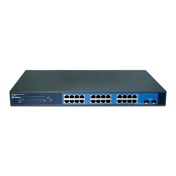
Web Smart Switch w/ 2 Shared Mini-GBIC Slots. Terms/Usage In this guide, the term “Switch” (first letter upper case) refers to your TEG-240WS 24-Port Gigabit Web Smart Switch w/ 2 Shared Mini- GBIC Slots and “switch” (first letter lower case) refers to other... -
Page 11: Introduction
The increased speed and extra bandwidth offered by Gigabit Ethernet is essential to coping with the network bottlenecks that frequently develop as computers and their busses get faster and more users use applications that generate more traffic. Upgrading key components,... -
Page 12: Fast Ethernet Technology
In addition, the phenomenal bandwidth delivered by Gigabit Ethernet is the most cost-effective method to take advantage of today and tomorrow’s rapidly improving switching and routing internetworking technologies. And with expected advances in the coming years in silicon technology and digital signal processing that will enable... -
Page 13: Switching Technology
Routers have also been used to segment local area networks, but the cost of a router, the setup and maintenance required make routers relatively impractical. Today switches are an ideal... -
Page 14: Vlan (Virtual Local Area Network)
VLAN (Virtual Local Area Network) A VLAN is a group of end-stations that are not constrained by their physical location and can communicate as if a common broadcast domain, a LAN. The primary utility of using VLAN is to reduce latency and need for routers, using faster switching instead. - Page 15 Supports IEEE 802.3x flow control for full-duplex mode ports Supports IEEE 802.1Q VLAN Supports IEEE 802.1p Priority Queues Supports Static Port Trunk Supports IGMP Snooping Supports SNMP for RFC1213 MIB II and Private MIB Supports IEEE 802.1D Spanning Tree Supports 802.1x port based access control...
-
Page 17: Unpacking And Installation
Specifications for the acceptable temperature and humidity operating ranges. Install the Switch in a site free from strong electromagnetic field generators (such as motors), vibration, dust, and direct exposure to sunlight. Leave at least 10cm of space at the front and rear of the hub for ventilation. -
Page 18: Rack Mounting
Install the Switch on a sturdy, level surface that can support its weight, or in an EIA standard-size equipment rack. For information on rack installation, see the next section, Rack Mounting. When installing the Switch on a level surface, attach the rubber feet to the bottom of each device. -
Page 19: Connecting Network Cable
Ethernet runs in full duplex mode using four pairs of Category 5 cable. These 1000BASE-T ports are Auto-MDI type port. The Switch can auto transform to MDI-II or MDI-X type, so you can just make an easy connection that without worrying if you are using a standard or crossover twisted-pair cable. -
Page 20: Ac Power
AC Power The Switch used the AC power supply 100-240V AC, 50-60 Hz. The power switch is located at the rear of the unit adjacent to the AC power connector and the system fan. The switch’s power supply will adjust to the local power source automatically and may be turned on... -
Page 21: Identifying External Components
10/100/1000Mbps and auto MDI/MDIX crossover detection function, this function gives true “plug and play” capability, just need to plug-in the network cable to the hub directly and don’t care if the end node is NIC (Network Interface Card) or switch and hub. -
Page 22: Rear Panel
100-240V AC at 50-60Hz. Reset: The Reset button is to reset all the setting back to the factory default. Note: Be sure that you recorded the setting of your device, else all the setting will be erased when pressing the “Reset” button. -
Page 23: Understanding Led Indicators
Power and System LEDs POWER: Power Indicator : When the Power LED lights on, the Switch is receiving power. : When the Power turns off or the power cord has improper connection. SYSTEM: Management Indicator Blinking : When the CPU is working, the System LED is blinking. -
Page 24: 1000Base-T Port 1~24 Status Leds
1000Mbps Gigabit Ethernet network. Amber When the Speed LED lights amber, the respective port is connected to a 100Mbps Fast Ethernet network. When the Speed LED lights off, the respective port is connected to a 10Mbps Ethernet network. -
Page 25: Mini-Gbic Port 23 ~ 24 Status Leds
1000Mbps Gigabit Ethernet network. Amber When the Speed LED lights amber, the respective port is connected to a 100Mbps Fast Ethernet network. When the Speed LED lights off, the respective port is connected to a 10Mbps Ethernet network. -
Page 27: Configuration
CONFIGURATION Through the Web Browser you can configure the Switch such as VLAN, Port Trunking, Jumbo Frame… etc. With the attached Web Management Utility, you can easily discover all the Web Management Switch, assign the IP Address, changing the password and upgrading the new firmware. -
Page 28: Discovery List
By pressing the “Discover” button, you can list all the Web Management devices in the discovery list. Double click or press the “Add to monitor list” button to select a device from the Discovery List to the Monitor List. -
Page 29: Monitor List
Gateway: Shows the Gateway set of the device. Monitor List All the Web Smart Device in the Monitor List can be monitored; you can also receive the trap and show the status of the device. System word definitions in the Monitor List: S: Shows the system symbol of the Web-Smart device, represent for device system is not alive. - Page 30 Figure 10. Trap Information Note: In order to receive Trap information, switch has to be configured with Trap IP and Trap Events in Web browser, which are available in the Trap Setting Menu (see Page 56 for detail). Add Item: To add a device to the Monitor List manually, enter the IP...
-
Page 31: Device Setting
Select the device in the Discovery list or Monitor List and press this button, then the Configuration Setting window will pop out as Figure 10, after filling up the data that you want to change, you must fill up the password and press the “Set” to process the data changed immediately. - Page 32 Figure 12. Password Change Firmware Upgrade: When the device has a new function, there will be a new firmware to update the device, use this function to update. Select the path of where the firmware updated firmware is located by clicking “Browse”.
-
Page 33: Toolbar
Choose 15 secs, 30 secs, 1 min, 2 min and 5 min to select the time of monitoring. In the “Help TAB”, there is About function, it will show out the version of the Web Management Utility. -
Page 34: Login
Before you configure this device, note that when the Web Smart Switch is configured through an Ethernet connection, make sure the manager PC must be set on same the IP network. For example, when the default network address of the default IP address of the Web Smart Switch is 192.168.0.1, then the manager PC should be set at... -
Page 35: Setup Setting
Figure 15. After entering the password, the main page comes up, the screen will display the device status. Figure 16. System Information Setup Setting Find that there are seven items, including Port Setting, IEEE 802.1Q VLAN Settings, Trunk Setting, Mirror Setting, IEEE 802.1p Default... -
Page 36: Port Settings
Link Status, press the Refresh button. The Link Status in the screen will show the connection speed and duplex mode; else this dialog box will show Down when the port is disconnected. Figure 17. Port Setting Note: The priority of Gigabit Fiber port is higher than Copper. -
Page 37: Ieee 802.1Q Vlan
802.1p Default Priority. IEEE 802.1Q VLAN A VLAN is a group of ports that can be anywhere in the network, but communicate as though they were in the same area. VLANs can be easily organized to reflect department groups (such as R&D, Marketing), usage groups (such as e-mail), or multicast groups... - Page 38 Asymmetric VLAN function. Figure 18. Enabled Asymmetric VLAN function Figure 19. Change setting warning message Note: The Settings of VLAN, IGMP Snooping and Forwarding Table will be reset to default. Untag Asymmetric VLAN Setting: The IEEE 802.1Q VLAN Configuration page provides powerful VID management functions.
- Page 39 Figure 20. 802.1Q Asymmetric VLAN Setting Add VID: Click to create a new VID group, assigning ports 1 ~ 24 as Untag, Tag, or Not Member. A port can be “Untagged” in only one VID. To save the VID group, press Apply.
- Page 40 IEEE 802.1Q VLAN setting. Figure 23. Modify VID PVID settings: While receiving an untagged frame from the port, the switch will assign a tag to the frame, using the PVID of the port as its VID. Figure 24. PVID Setting...
- Page 41 VLAN 1 (VID 01) does not have communication with VLAN 2 (VID 02). Figure 25. Step1: Set VLAN1 port 9~24 to “Not Member”, then apply setting. Figure 26. Step2: Create VID 02 and set port 9~24 to “Untag Port” member, then apply setting. Figure 27.
- Page 42 Example2: 802.1Q Asymmetric VLAN settings example: Port 1~16 in VLAN 1, port1~5 in VLAN 2, port1,6~9 in VLAN 3. All VLAN1~3 have access to Internet via port 1. Figure 28. Note: The multi-need server must be support IEEE 802.1Q VLAN Step1: Enable Asymmetric VLAN function.
- Page 43 Step3: Create VID 02 and set port 1~5 to “Untag” ports and port 6~24 to “Not Member” ports, then apply setting. Figure 31. Step4: Create VID03 and set port 1 and 6~9 to “Untag” ports, then apply setting. Figure 32.
-
Page 44: Tag Vlan Setting
1. Untag port VLAN member can exist in different VLAN groups simultaneously when Asymmetric VLAN function enabled. 2. You must create VLAN and add VLAN member first that just can set PVID setting. 3. You must change Untag Port PVID to another existent VLAN ID that just can... - Page 45 Step1: Set VLAN1 port 1 to “Tag” and port 9~24 to “Not Member”, then apply setting. Figure 35. Step 2: Create VID 02 and set port 1 to “Tag” port and port 9~24 to “Untag” ports, then apply setting. Figure 36.
- Page 46 Example 4: Setting Tag VLAN on two switches. Switch 1’s VLAN 1 (2 ~ 3 ports) have access to the Switch 2’s VLAN 1 (2 ~ 3 ports). The settings of VLAN group for two devices are same. Step1: Set Switch1’s VLAN1 port 1and 4~24 to “Not Member”, then apply setting.
-
Page 47: Trunk Setting
The Trunking function enables the cascading of two or more ports for a combined larger bandwidth. Up to six Trunk groups may be created, each supporting up to 8 ports. Add a Trunking Name and select the ports to be trunked together, and click Apply to activate the selected Trunking groups. -
Page 48: Mirror Setting
RX (receive) mode: this mode will duplicate the data that send to the source and forward to the Sniffer port. Both (transmit and receive) mode: this mode will duplicate both the data transmit from and data that send to the source port, then it will forward to the Sniffer port. -
Page 49: Ieee 802.1P Default Priority
IEEE 802.1p Default Priority This feature displays the status Quality of Service priority levels of each port, and for packets that are untagged, the switch will assign the priority in the tag depending on your configuration. Figure 40 IEEE 802.1p Default Priority Setting... -
Page 50: Broadcast Storm Control Setting
If Enabled (default is Disabled), threshold settings of 8,000 ~ 4,096,000 bytes per second can be assigned. Press Apply for the settings to take effect. Figure 18. Broadcast Storm Control Setting Jumbo Frame Setting Jumbo Frames enable the transportation of identical data in fewer frames. -
Page 51: Advanced Setting
SNMP Setting The Web Smart Switch supports SNMP include software (referred to as an agent), which runs locally on the device. A defined set of variables (managed objects) is maintained by the SNMP agent and used to manage the device. These objects are defined in a... - Page 52 Trap Name: Enter a Trap Name (i.e. Trap Name must be selected from a Community Name) IP: Enter the IP of the device to be monitored, and choose the event(s) to trap. Event: The available trap Events to choose from include: System...
-
Page 53: Spanning Tree Setting
The Web Smart Switch supports IEEE 802.1D Spanning Tree Protocol (STP) implementation is designed to prevent network loops that could cause a broadcast storm. When the physical links forming a loop provide redundancy, only a single path will be forwarding frames. - Page 54 Set by the Root Bridge, this value will aid in determining that the Switch has spanning tree configuration values consistent with other devices on the bridged LAN. If the value ages out and a BPDU has still not been received from the Root Bridge, the Switch will start sending its own BPDU to all other switches for permission to become the Root Bridge.
-
Page 55: 802.1X Setting
802.1x holds a network port disconnected until authentication is completed. Depending on the results, the port is either made available to the user, or the user is denied access to the network. 802.1X uses the Extensible Authentication Protocol (EAP) for passing authentication messages. - Page 56 Default is 1812. Key/Confirm Key: Masked password matching the Radius Server Key. TxPeriod: Sets the number of seconds that the switch waits for a response to an EAP-request/identity frame from the client before retransmitting the request. Default is 24 seconds.
-
Page 57: Igmp Snooping Setting
With Internet Group Management Protocol (IGMP) snooping, the Web-Smart Switch can make intelligent multicast forwarding decisions by examining the contents of each frame’s Layer 2 MAC header. IGMP snooping can help reduce cluttered traffic on the LAN. With IGMP snooping enabled globally, the Web-Smart Switch will forward IP multicast traffic only to connections that have group members attached. - Page 58 Adjusting this setting effects the "leave latency", or the time between the moment the last host leaves a group and when the routing protocol is notified that there are no more members. It also allows adjustments for controlling the frequency of IGMP traffic on a subnet.
-
Page 59: Igmp Vlan Setting
Leave Timer (0-25 sec): This is the interval after which a Leave message is forwarded on a port. When a leave message from a host for a group is received, a group-specific query is sent to the port on which the leave message is received. - Page 60 Figure 25. IGMP-Router Port Setting To view the Multicast Entry Table for a given VLAN, press the View button. Figure 26. IGMP – Multicast Entry Table Setting...
-
Page 61: System Setting
System Information Press on “System Information” to display the system information status on this screen, it will show the Product Name, Firmware Version, Protocol Version, MAC Address, System Name, Location Name, IP Address, Subnet Mask, Default Gateway, Trap IP, Login Timeout and System Up Time. -
Page 62: System Setting
When using static mode, the IP Address, Subnet Mask and Gateway can be manually configured. When using DHCP mode, the Switch will first look for a DHCP server to provide it with an IP address, network mask, and default gateway before using the default or previously entered settings. - Page 63 Figure 28. System Setting...
-
Page 64: Trap Setting
System Events: Monitoring the system’s trap. Device Bootup: a trap when booting up the system. Illegal Login: a trap when there is using a wrong password login, and it will record from where the IP to be login. Fiber Port Event: Monitoring the Fiber port status. -
Page 65: Password Setting
Web Smart Switch. After entering the old password and the new password two times, press Apply for the changes to take effect. If you forget the password, press the “Reset” button in the front panel of the Switch. Note: All current settings will be erased when pressing the “Reset”... -
Page 66: Statistic
Statistic The Statistic Menu screen will show the status of each port packet count. Figure 31. Statistics Refresh: To renew the details collected and displayed. Clear Counter: To reset the details displayed. - Page 67 To view the statistics of individual ports, click one of the Port ID as Error! Reference source not found.. Figure 32. Port Statistics...
-
Page 68: Factory Reset
Factory Reset The Factory Reset helps you to reset the device back to the default setting from the factory. All of the configuration will be reset, the IP address of the device will be set to default setting 192.168.0.1. Figure 33. Factory Reset... -
Page 69: Firmware Upload
Figure 35. Firmware Upload System Reboot Provides to a safe way to reboot the system, ensure the configuration has been saved, or all the changes you just made may be lost after system reboot. Figure 36. System Reboot... -
Page 70: Logout
Logout When pressed you will logout of the web configuration page and will return to the first Login page. Figure 37. -
Page 71: Technical Specifications
IEEE 802.3 10BASE‐T Ethernet IEEE 802.3u 100BASE‐TX Fast Ethernet IEEE 802.3ab 1000BASE‐T Gigabit Ethernet IEEE 802.3x Full Duplex Flow Control IEEE 802.3z 1000BASE‐SX/LX Gigabit Ethernet Protocol CSMA/CD Data Transfer Ethernet: 10Mbps (half‐duplex), 20Mbps (full‐duplex) Rate Fast Ethernet: 100Mbps (half‐duplex), 200Mbps (full‐duplex) Gigabit Ethernet: 2000Mbps (full‐duplex) Topology Star Network Cables 10BASET: 2‐pair UTP Cat. 3, 4, 5; up to 100m 100BASE‐TX: 2‐pair UTP Cat. 5; up to 100m 1000BASE‐T: 4‐pair UTP Cat. 5; up to 100m Fiber module: Mini‐GBIC Fiber module (LC‐Type Cable) Number of Ports 24 × 10/100/1000Mbps Auto‐MDIX RJ‐45 ports 2 × Combo mini‐GBIC slots Physical and Environmental AC inputs 100‐240V AC, 50‐60Hz internal universal power supply Power 35 Watts (max) Consumption Temperature Operating: 0~ 40 C, Storage: ‐10 ~ 70 C Humidity Operating: 10% ~ 90%, Storage: 5% ~ 90% Dimensions 440 x 210 x 44mm (W x H x D) Certification CE, FCC ... - Page 72 Performance Transmits Store‐and‐forward Method: RAM Buffer: 512KBytes per device Filtering Address 8K entries per device Table: MAC Address Automatic update Learning: Packet Filtering / 10Mbps Ethernet: 14,880/pps Forwarding Rate: 100Mbps Fast Ethernet: 148,800/pps 1000Mbps Gigabit Ethernet: 1,488,000/pps ...
- Page 73 All products that are replaced become the property of TRENDnet. Replacement products may be new or reconditioned. TRENDnet does not issue refunds or credit. Please contact the point‐of‐purchase for their return policies. TRENDnet shall not be responsible for any software, firmware, information, or memory data of customer contained in, stored on, or integrated with any products returned to TRENDnet pursuant to any warranty. There are no user serviceable parts inside the product. Do not ...
- Page 74 This warranty is voided if (i) the product has been modified or repaired by any unauthorized service center, (ii) the product was subject to accident, abuse, or improper use (iii) the ...
- Page 75 LIABILITY, WHETHER BASED IN CONTRACT OR TORT (INCLUDING NEGLIGENCE), FOR INCIDENTAL, CONSEQUENTIAL, INDIRECT, SPECIAL, OR PUNITIVE DAMAGES OF ANY KIND, OR FOR LOSS OF REVENUE OR PROFITS, LOSS OF BUSINESS, LOSS OF INFORMATION OR DATE, OR OTHER FINANCIAL LOSS ARISING OUT OF OR IN ...
- Page 76 Go to http://www.trendnet.com/gpl or http://www.trendnet.com Download section and look for the desired TRENDnet product to access to the GPL Code or LGPL Code. These codes are distributed WITHOUT WARRANTY and are subject to the copyrights of the developers. TRENDnet does not provide technical support for these ...