Table of Contents
Advertisement
Quick Links
Advertisement
Table of Contents

Related Manuals for Yamaha HTR-6050


Summary of Contents for Yamaha HTR-6050
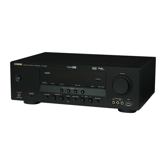
- Page 1 HTR-6050 AV Receiver OWNER’S MANUAL...
-
Page 2: Important Safety Instructions
If QUALIFIED SERVICE PERSONNEL. you are not sure of the type of power supply to your home, consult your product dealer or local power company. For products intended to operate from battery power, or other •... - Page 3 – NATIONAL ELECTRICAL CODE guidelines for proper grounding and, in particular, specifies that the cable ground shall be connected to the grounding system of the building, as close to the point of cable entry as practical. FCC INFORMATION (for US customers)
- Page 4 Allow ventilation space of at least 18 Before moving this unit, press STANDBY/ON to set this unit 30 cm on the top, 20 cm on the left and right, and 20 cm on in the standby mode, and disconnect the AC power plug from the back of this unit.
-
Page 5: Table Of Contents
Creating your original SCENE templates....31 • Some operations can be performed by using either the Playback ..............32 buttons on the front panel or the ones on the remote control. Basic operations............32 In case the button names differ between the front panel and Additional operations.......... -
Page 6: Features
100 W (1 kHz, 0.9% THD, 6 Ω) USB features SCENE select function ◆ USB port to connect a USB memory device or a USB portable ◆ Preset SCENE templates for various situations audio player ◆ SCENE template customizing capability ◆... -
Page 7: Getting Started
Snap the battery compartment cover back into place. Notes • Change all of the batteries if you notice the following condition: – the operation range of the remote control decreases. • Do not use an old battery and a new one together. -
Page 8: Quick Start Guide
Front left Surround right speaker ❏ Indoor FM antenna speaker ❏ AM loop antenna The following items are not included in the package of this unit. Center speaker ❏ Speakers ❏ Front speakers ........2 DVD player ❏ Center speaker ........1 ❏... -
Page 9: Step 1: Set Up Your Speakers
Be sure to connect the left channel (L), right channel Step 1: Set up your speakers (R), “+” (red) and “–” (black) properly. Front speakers Place your speakers in the room and connect them to this unit. ANTENNA SPEAKERS AC OUTLETS... -
Page 10: And Other Components
Quick start guide Step 2: Connect your DVD player Connect the video cable to the composite and other components video output jack of your DVD player and the DVD VIDEO jack of this unit. ANTENNA SPEAKERS AC OUTLETS AV receiver... - Page 11 ☞ P. 20 • Using the USB jack on the front panel ☞ P. 43 The wire of the AM loop antenna does not have any polarity and you can connect either end of the wire to AM and GND terminal. Note The shape of the AM and GND terminals may vary depending on the unit.
-
Page 12: Step 3: Turn On The Power And Press Scene 1 Button
In the following cases, try pressing the corresponding SCENE button to enjoy playback of the desired sources. Case A: “I want to listen to a music disc from the connected DVD player as the back ground music for this room...”... -
Page 13: What Do You Want To Do With This Unit
☞ P. 39 ■ Adjusting the parameters of this unit • Automatically optimizing the speaker This unit is set to the standby mode. To turn on this unit parameters for your listening room from the standby mode, press 1 STANDBY/ON (or (AUTO SETUP) M POWER). -
Page 14: Connections
See page 21 for connection information. 2 HDMI jacks 7 DIGITAL INPUT jacks See page 17 for connection information. See pages 16 and 19 for connection information. 3 VIDEO jacks 8 MULTI CH INPUT jacks See pages 16 and 18 for connection information. -
Page 15: Placing Speakers
Center speaker (C) The center speaker is for the center channel sounds (dialog, vocals, etc.). If for some reason it is not practical to use a center speaker, you can do without it. Best results, however, are obtained with the full system. -
Page 16: Connecting Speakers
• Use the magnetically shielded speakers. If this type of speaker still creates interference with the monitor, place the speakers away from the monitor. • If you are to use 6 ohm speakers, be sure to set “SP IMP.” to “6Ω MIN” before using this unit (see page 13). Note A speaker cable is actually a pair of insulated cables running side by side. -
Page 17: Setting The Speaker Impedance
Cables are colored or shaped Caution differently, perhaps with a stripe, groove or ridges. If you are to use 6 ohm speakers, set “SP IMP.” to “6Ω Connect the striped (grooved, etc.) cable to the “+” (red) MIN” as follows BEFORE using this unit. -
Page 18: Information On Jacks And Cable Plugs
• Pull out the cap from the optical jack before you connect the optical digital audio cable. Do not discard the cap. When you S VIDEO are not using the optical jack, be sure to put the cap back in place. This cap protects the jack from dust. VIDEO Note The OSD signal is not output at the DVR OUT (REC) jacks. -
Page 19: Information On Hdmi
Connections Information on HDMI™ Audio signals input at the HDMI jack are not output from any speaker terminals but output from the connected video monitor. To enjoy the sound from speakers connected to this unit, – make an analog or digital connection besides the HDMI connection (see page 16). -
Page 20: Connecting Video Components
Make sure that this unit and other You can also connect a video monitor, DVD player, digital TV, components are unplugged from the and cable TV to this unit using the S VIDEO or COMPONENT AC wall outlets. VIDEO connections (see page 17). -
Page 21: Connecting To Component Video Jacks
Note Be sure to connect your video components in the same way you connect your video monitor to this unit. For example, if you connect your video monitor to this unit using a HDMI connection, connect your video components to this unit using the HDMI connection. - Page 22 Connections COMPONENT VIDEO connection S VIDEO connection Video monitor Video monitor Cable TV or DVD player satellite tuner DTV/CBL HDMI VIDEO COMPONENT VIDEO DTV/CBL MONITOR DTV/CBL MONITOR S VIDEO VIDEO AUDIO MULTI CH INPUT FRONT SURROUND CENTER SUBWOOFER DVD player...
-
Page 23: Connecting Audio Components
Connect the output jacks on your multi-format player or external decoder to the MULTI CH INPUT jacks. Be sure to match the left and right output jacks to the left and right input jacks for the front and surround channels. -
Page 24: Using The Video Aux Jacks On The Front Panel
Connecting the FM and AM front panel antennas Use the VIDEO AUX jacks on the front panel to connect a Both FM and AM indoor antennas are supplied with this game console or a video camera to this unit. unit. In general, these antennas should provide sufficient signal strength. -
Page 25: Connecting The Power Cable
Press 1 STANDBY/ON (or M POWER) to turn AC OUTLETS on this unit. When you turn on this unit, there will be a 4 to 5-second delay before this unit can reproduce sound. ■ Set this unit to the standby mode Press 1 STANDBY/ON (or N STANDBY) to set this unit to the standby mode. -
Page 26: Front Panel Display
Lights up while the sleep timer is on (see page 36). 7 Tuner indicators G Input channel and speaker indicators Lights up when this unit is in the FM or AM tuning mode (see pages 40). LFE indicator 8 MUTE indicator... -
Page 27: Using The Remote Control
• Do not spill water or other liquids on the remote control. • Do not drop the remote control. • Do not leave or store the remote control in the following types of conditions: – places of high humidity, such as near a bath –... -
Page 28: Optimizing The Speaker Setting For Your Listening Room
This unit employs the YPAO (Yamaha Parametric Room Acoustic Optimizer) technology which lets you avoid troublesome listening-based speaker setup and achieves highly accurate sound adjustments automatically. The supplied optimizer microphone collects and this unit analyzes the sound your speakers produce in your actual listening environment. - Page 29 Speaker distance DIST operation on this unit. Displays the speaker distance from the listening position • We recommend getting out of the room while this unit is in in the following order: the auto setup procedure. It takes approximately 3 minutes Closest speaker distance/Farthest speaker distance for this unit to complete the auto setup procedure.
- Page 30 The optimizer microphone is sensitive to heat. Keep it away from direct sunlight and do not place it on top If you are not satisfied with the results or want to manually adjust each parameter, run “MANUAL SETUP” (see of this unit.
- Page 31 ■ If an error screen appears ■ If “WARNING” appears When this unit detects potential problems during the Press G k / n / l / h to select “RETRY” or “AUTO SETUP” procedure, “WARNING” appears in the “EXIT” and then press G ENTER.
-
Page 32: Selecting The Scene Templates
Notes front panel starts to flash, and the name of the • If you do not carry out any operation within 30 seconds from currently assigned SCENE template appears in the the last operation in these steps, this procedure is automatically front panel display. - Page 33 USB memory device or USB portable USB Audio Listening audio player DTV/CBL TV programs TV Viewing TV Sports Viewing Video games V-AUX Game Playing You can create your original SCENE templates by editing the preset SCENE templates. See page 31 for details.
- Page 34 Selecting the SCENE templates ■ Preset SCENE templates descriptions CD Listening SCENE template Select this SCENE template when you play back music discs on Features your CD player. Input source Playback mode 2ch Stereo DVD Viewing CD Music Listening (SCENE 1 as the default setting)
-
Page 35: Creating Your Original Scene Templates
When the SCENE template you want to customize is not preset SCENE templates” and then press assigned to any of the E SCENE button, press G l / h G ENTER. repeatedly to recall the desired SCENE template on the •... -
Page 36: Playback
Extreme caution should be exercised when you play and then J PROG l / h) repeatedly to back CDs encoded in DTS. If you play back a CD select the desired sound field program. encoded in DTS on a DTS-incompatible CD player,... -
Page 37: Additional Operations
Press 9 SPEAKERS on the front panel • You can adjust the default audio input jack select of this unit by using “AUDIO SELECT” in “OPTION MENU” (see page 55). repeatedly to turn on or off the set of front... -
Page 38: Adjusting The Tonal Quality
Press D AMP and then press F LEVEL Notes repeatedly to select the speaker you want to • To avoid unexpected noise, do not play CDs encoded in DTS adjust. when the DIRECT STEREO mode is selected. • When multi-channel signals (Dolby Digital and DTS) are input,... -
Page 39: Selecting The Night Listening Mode
• Select “NIGHT:MUSIC” to preserve ease-of- .A;SIGNAL INFO listening for all sounds. [ ]/[ ]:Up/Down • Select “OFF” if you do not want to use this feature. [ENTER]:Enter When a night listening mode is selected, the NIGHT Press G n repeatedly to select “SIGNAL indicator lights up in the front panel display. -
Page 40: Muting The Audio Output
• You can also rotate 8 VOLUME (or press R VOLUME +/–) to resume the audio output. Press the input selector buttons on the remote •... -
Page 41: Sound Field Programs
The sound field programs of this unit are recreations of real-world acoustic environments made from precise measurements taken in the actual concert hall, music venue, movie theater, etc. Thus, you may notice variations in the strength of the reflections coming from each... -
Page 42: Enjoying Unprocessed Input Sources
Dolby Pro Logic processing for any SILENT CINEMA does not activate when the component PRO LOGIC sources connected to the MULTI CH INPUT jacks is selected as the input source (see page 33). Dolby Pro Logic II processing for PLII Movie ■... - Page 43 Sound field programs ■ Editing sound fields parameters You can enjoy good quality sound with the factory preset parameters. Although you do not have to change the initial settings, you can change some of the parameters to better suit the input source or your listening room.
-
Page 44: Fm/Am Tuning
There are 2 tuning methods: automatic and manual. Automatic tuning is effective when station signals are strong and there is no interference. If the signal from the station you want to select is weak, tune into it manually. You can also use the automatic and manual preset tuning features to store up to 40 stations. -
Page 45: Automatic Preset Tuning
Manual preset tuning You can use the automatic preset tuning feature to store You can also store up to 40 stations (A1 to E8: 8 preset FM stations with strong signals up to 40 (A1 to E8: 8 station numbers in each of the 5 preset station groups) preset station numbers in each of the 5 preset station manually. -
Page 46: Selecting Preset Stations
“A5” and the MEMORY indicator flash in the front E1 FM 87.5 MHz panel display. See “Selecting preset stations” on this page. You can select the desired preset station number (1 to 8) directly Flashes by pressing the numeric buttons on the remote control. MEMORY A5 FM 90.7 MHz... -
Page 47: Using A Usb Memory Device Or A Usb Portable Audio Player
Using a USB memory device or a USB portable audio player Use this feature to enjoy WAV (PCM format only), MP3 and WMA files saved on your USB memory device or USB portable audio player connected to the USB port on the front panel of this unit. - Page 48 I h / s to start/stop playback independently from the menu 2 Name of the album in the OSD. • You can set the settings for repeat and shuffle mode by using the 3 Name of the song “USB PLAY STYLE” parameters in “OPTION MENU” (see 4 Elapsed time page 55).
-
Page 49: Recording
• A given input source is not output on the same OUT (REC) channel. • Once you have connected a recording component to this unit, keep the component turned on while using this unit. If the component is turned off, this unit may distort the sound from other components. -
Page 50: Set Menu
Use this feature to manually adjust speaker and system parameters. Sound menu 1 SOUND MENU Use this menu to manually adjust any speaker settings, alter the quality and tone of the sound output by the system or compensate for video signal processing delays when using LCD monitors or projectors. -
Page 51: Using Set Menu
B)MEMORY GUARD Locks sound field program parameters and other “SET MENU” settings. Designates the default audio input jack select setting for the input sources connected to the C)AUDIO SELECT DIGITAL INPUT jacks when you turn on the power of this unit. -
Page 52: Sound Menu
NONE >SML Notes When the center speaker is large • If you connect headphones to the PHONES jack of this unit, the Select “LRG” (large). sound is output from both headphones and the FRONT B terminals when “FRONT B” is set to “ZONE B”. - Page 53 Surround left/right speakers SUR. L/R SP Crossover CROSSOVER Choices: NONE, SML, LRG Use this feature to select a crossover frequency of all the speakers set to “SML” (or “SMALL”) or to “NONE” in “SPEAKER SET” (see pages 47 and 48). All frequencies...
- Page 54 However, this is not possible in Initial setting: 0 dB most home situations. Thus, a certain amount of delay must be applied to the sound from each speaker so that all sounds will arrive at the listening position at the same 1 SOUND MENU time.
- Page 55 Use this feature to adjust the overall audio settings of this ■ Low-frequency effect level E)LFE LEVEL unit. Use this feature to adjust the output level of the LFE (low- frequency effect) channel according to the capacity of 1 SOUND MENU your subwoofer or headphones. The LFE channel carries...
-
Page 56: Input Menu
[ENTER]:Enter setting. For example, if “INI.VOL.” is set to –20 dB and “MAX VOL.” is set to –30 dB, the volume level is automatically set to ■ Input assignment –30 dB when you turn on the power of this unit next time. - Page 57 A to Z, a space, 0 to 9, a space, a to z, a space, symbols (#, source. *, –, +, etc.)
-
Page 58: Option Menu
Front panel display scroll FL SCROLL E)MULTI CH SET Use this feature to set whether to display the information (such as a song title or a channel name) in the front panel display in a continuous manner or by the first 14 2 INPUT MENU... - Page 59 • Select “ALL” to set this unit to repeat a sequence of files. Shuffle SHUFFLE Use this feature to set this unit to play files or folders in a random order. Choices: OFF, ON • Select “OFF” to deactivate this feature.
-
Page 60: Remote Control Features
In addition to controlling this unit, the remote control can also operate other audiovisual components made by Yamaha and other manufacturers. To control your TV or other components, you must set up the appropriate remote control code for each input source (see page 59). -
Page 61: Controlling This Unit, A Tv, Or Other Components
These buttons always control this unit regardless of the Notes operation mode selector position. These buttons control this unit only when D AMP is pressed. These buttons always control your TV regardless of whether you press C DTV/CBL or not. -
Page 62: Controlling Other Components
Index Notes This button is operational only when the original remote control supplied with the component has a POWER button. These buttons operate your DVD recorder only when you set the appropriate remote control code for DVR (see page 59). -
Page 63: Setting Remote Control Codes
• If the manufacturer of your component has more than one code, YAMAHA 5012 try each of them until you find the correct one. • If you do not press any buttons within 30 seconds in step 2, the YAMAHA 2011 setup process is canceled. If this happens, repeat the setup procedure. -
Page 64: Advanced Setup
Change the initial settings (indicated in bold Choices: 8Ω MIN, 6Ω MIN • Select “8Ω MIN” to set the speaker impedance to 8 Ω . under each parameter) to reflect the needs of your • Select “6Ω MIN” to set the speaker impedance to 6 Ω . -
Page 65: Troubleshooting
Troubleshooting Refer to the table below when this unit does not function properly. If the problem you are experiencing is not listed below or if the instruction below does not help, turn off this unit, disconnect the power cable, and contact the nearest authorized Yamaha dealer or service center. - Page 66 The sleep timer has turned off this unit. Turn on this unit, and play the source again. — The sound is muted. Press O MUTE or R VOLUME +/– on the remote control to resume audio output. Sound is heard from Incorrect cable connections.
- Page 67 This unit suddenly The internal temperature is too high and Wait about 1 hour for this unit to cool down and then enters the standby the overheat protection circuitry has been turn it back on.
-
Page 68: Auto Setup
There are continuous Noise can result from lightning, Use an outdoor antenna and a ground wire. crackling and hissing fluorescent lamps, motors, thermostats This will help somewhat, but it is difficult to — noises. and other electrical equipment. eliminate all noise. - Page 69 — Notes • If the “ERROR” or “WARNING” screens appears, check the cause of the problem, then run “AUTO SETUP” again. • If a warning message “W-1” appears, corrections are made, but they may not be optimal. • If a warning message “W-2” or “W-3” appears, no corrections are made.
- Page 70 USB mass storage class USB memory class USB memory device (except USB hard disk device or USB portable audio player. drives) or USB portable audio player. Also note that it cannot recognize certain USB devices even when they are devices as described above.
-
Page 71: Resetting The System
Wrong distance or angle. The remote control functions within a maximum does not work nor range of 6 m (20 ft) and no more than 30 degrees off- function properly. axis from the front panel. Direct sunlight or lighting (from an Reposition this unit. -
Page 72: Glossary
This channel reproduces low-frequency bass signals. The minimum volume reproduced by the 5 full-range channels frequency range of this channel is from 20 Hz to 120 Hz. and the precise sound orientation generated using digital This channel is counted as 0.1 because it only enforces a... -
Page 73: Sound Field Program Information
Since the Dolby Surround and DTS systems were as the Y signal for the luminance and the C signal for the originally designed for use in movie theaters, their effect chrominance through the S-video cable. Using the S... -
Page 74: Specifications
• Frequency Response (MONITOR OUT) • Maximum Input Signal Component Signal ........5 Hz to 60 MHz, –3 dB CD, etc. Effect On, 1 kHz, 0.5% THD ....2.0 V or more FM SECTION • Frequency Response • Tuning Range ............. 87.5 to 107.9 MHz CD, etc. -
Page 75: Index
Numerics Center width, DIMENSION, Sound field parameter ......39 Sound field parameter ..... 39 1 SOUND MENU, Manual setup ..46 CHANNEL, Dimension, Sound field parameter ..39 2 INPUT MENU, Manual setup ..46 Input source information ....35 DIMMER, Display settings ....54 2ch Stereo, Sound field program .. - Page 76 Pure hi-fi stereo sound ......34 Game ............ 37 with headphones ......38 ■ ■ Multi-information display, Remote control code default setting ..59 Front panel display ......22 Hall ............37 Remote control code setting ....59 Music Enh. 2ch, HDMI ........... 15 Remote control codes ......
- Page 77 Speaker settings ....... 49 Subwoofer phase, Speaker settings ..49 ■ Supplied accessories ......3 Zone B ..........33 SUR. L/R SP, Speaker settings .... 49 Surround left/right speakers, Speaker settings ....... 49 ■ Test tone, Center speaker equalizer ..51 TEST, Center speaker equalizer ..
-
Page 78: Front Panel
Front panel VOLUME OPTIMIZER MIC STANDBY EDIT PRESET/TUNING FM/AM A/B/C/D/E PRESET/TUNING MEMORY TUNING AUTO/MAN'L SCENE VIDEO AUX PROGRAM INPUT VIDEO AUDIO SPEAKERS PHONES TONE CONTROL STRAIGHT DIRECT STEREO AUDIO SELECT A/B/OFF EFFECT SILENT CINEMA... -
Page 79: Remote Control
AUDIO SEL SLEEP MUTE MD/CD-R TUNER TV CH DTV/CBL V-AUX TV VOL TV INPUT TV MUTE SCENE BAND LEVEL VOLUME TITLE MENU ENTER DISPLAY RETURN FREQ/TEXT MODE – PTY SEEK – START PROG h ENHANCER STRAIGHT SUR.DECODE NIGHT DIRECT ST. -
Page 80: List Of Remote Control Codes
List of remote control codes BELL & HOWELL DANTAX 0217 0204, 0207, 0211, 0058, 0064 DAYTRON 0060, 0061, 0208 0213, 0217 ACER 0093 BENQ 0051, 0081 DE GRAAF 0210 GELOSO 0208, 0210, 0215 ACME 0207 BEON 0213, 0217 DECCA 0204, 0207, 0213,... - Page 81 0063, 0128, 0203, 0218 PRECISION 0207 SCHNEIDER 0207, 0209, 0213, 0204, 0223, 0227 NIKKO 0061 PRIMA 0208, 0211 0215, 0216, 0217, LOEWE OPTA 0205, 0213, 0217 NOBLIKO 0200, 0207 PROFEX 0208 0218 LOGIK 0058 NOGAMATIC 0216 PROFI-TRONIC SCOTCH 0061 LUMA...
- Page 82 0061, 0063 SYMPHONIC 0062, 0080 1049 DVD/VCR COMBO SYSLINE 0217 WATSON 0213, 0217, 0218 DYNATECH 1005 SYTONG 0200 WATT RADIO 0200, 0207, 0212, 1017, 1017, 2045, ELECTROHOME TANDY 0127, 0207, 0209, 0215 2045 1003 0211, 0218 WEGA 0205 1071, 2087...
- Page 83 MEMOREX 1001, 1002, 1003, 1001, 1002, 1003, TOKAI 1045, 1050 1045 1004, 1005, 1008, 1004, 1005, 1008 TONSAI 1050 GOODMANS 1042, 1045, 1050, 1013, 1014, 1042, RADIOLA 1046 TOSHIBA 1013, 1024, 1029, 1069 1045, 1047 RADIX 1003 1043, 1046, 1066,...
- Page 84 YAMAHA ELECTRONICS (UK) LTD. YAMAHA HOUSE, 200 RICKMANSWORTH ROAD WATFORD, HERTS WD18 7GQ, ENGLAND YAMAHA SCANDINAVIA A.B. J A WETTERGRENS GATA 1, BOX 30053, 400 43 VÄSTRA FRÖLUNDA, SWEDEN YAMAHA MUSIC AUSTRALIA PTY, LTD. 17-33 MARKET ST., SOUTH MELBOURNE, 3205 VIC., AUSTRALIA...
- Page 86 MD/CD-R TUNER TV CH DTV/CBL V-AUX TV VOL TV INPUT TV MUTE SCENE BAND LEVEL VOLUME TITLE MENU ENTER DISPLAY RETURN FREQ/TEXT MODE – PTY SEEK – START PROG h ENHANCER STRAIGHT SUR.DECODE NIGHT DIRECT ST. Printed in China WK65650...