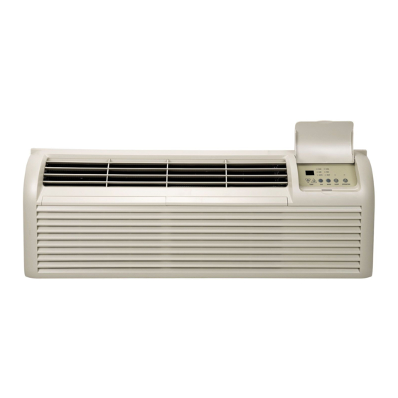
GE AZ41E09DAB Owner's Manual And Installation Instructions
Heat/cool model; heat pump model
Hide thumbs
Also See for AZ41E09DAB:
- Dimensions and installation information (2 pages) ,
- Owner's manual & installation instructions (72 pages)
Table of Contents
Advertisement
Quick Links
GEAppliances.com
0
0_
0_
0
U
.............
2
Operating Instructions
.......................
4
................
5-8
...........................
3
......
4
.................
4
Air Filters .........................
10
Base Pan ..........................
9
Outdoor Coils ......................
9
Room Cabinet and Case ............
9
Filter ....................
9
..........
13-16
.........
17, 18
Optional Drain Kit .................
19
Preparation
.......................
11
Replacing an Existing Unit7 ........
12
Sounds .........
22
Consumer Support ........
Back Cover
.........................
23
Heat/Cool
Model 4100
Heat Pump Model
6100
Espa_ol
For a Spanish version of this
manual, visit our Website at
www.zoneline.com/literuture.
Para consultar
una version
en espahol de este manual
de instrucciones,
visite nuestro
sitio de internet
www.zoneline.com/literature.
Frangais
For a French version of this
manual, visit our Website at
www.zoneline.com/literuture.
Pour un version frangais de
ce manuel d'utilisation,
veuillez
visiter notre site web 6 I'adresse
www.zoneline.com/literature.
Write the model and serial
numbers
here:
Model #
Serial #
Find these numbers on a label
behind the room cabinet on the
base pan.
TINSEA576JBRZ
49-7612-1
12-10 GE
Advertisement
Table of Contents

Related Manuals for GE AZ41E09DAB


Summary of Contents for GE AZ41E09DAB
-
Page 1: Table Of Contents
......To Remove the Room Cabinet ..Ventilation Control ....Espa_ol Care and Cleaning For a Spanish version of this manual, visit our Website at Air Filters ......www.zoneline.com/literuture. Base Pan ......Outdoor Coils ...... Para consultar una version Room Cabinet and Case .... -
Page 2: Safety Instructions
IMPORTANTSAFETYINFORMATION. READALL INSTRUCTIONSBEFOREUSING. WARNING! For your safety, the information in this manual must be followed to minimize the risk of fire or explosion, electric shock, or to prevent property damage, personal injury, or loss of life. SAFETY PRECAUTIONS This Zoneline must be properly installed •... -
Page 3: Controls
OPERATION--ON/STOP--Turns the unit on or off. Powerremains connectedto Sleep Press to set the air conditionerto run for 8 hours the Zoneline. T he Freeze/HeatSentinel features still function if active.See the before it automaticallyreturns to the previous Freezer/Heat S entinel s ection on page 6. -
Page 4: Air Direction
NOTE:Two shipping screws must be removed from the vent door before use.Seethe Installation Instructions in the back of this manual. If you do not plan to use the ventilation feature, leave these two screws in place. Theventilation control lever is located at the middle left side of the Zoneline unit, behind the room cabinet. -
Page 5: Auxiliary Controls
--HEAT on the main control will be lit. Pressthe down arrow Cooling - Continuous to set the indoor fan to cycle on/off when the unit is heating or cooling "u ." Pressthe up arrow to set -- HIGH -- COOL the indoor fan to run continuously"... - Page 6 Press MODE untila 3 appearsin the first digitof the displayfor Freeze S entinel OFF Freeze Sentinelmode.TheCOOL.LED l ightqn the maincontrol. will be on.Press HQDE again to chanqeto the Heat Sentinel. T he _COOL HEAT LEDlighton the maincontrolw_lbe on.Press the down arrowfor OFF "u "or the up arrowfor ON"n."...
- Page 7 To setAll-ElectricHeat option,press MODE until an 8 All-Electric All-Electric appears in the first digit of the display. Press the up or HeatOFF Heat O N down arrowkeysto set this switchto OFF "u" or ON"n." Thisisshownin the seconddigit of the display.
- Page 8 AConly. electronics can resultfrom improperconnections. S pecial If usinga digital/electronic wallthermostat,you mustset care mustbe usedin connectingthe wires.Noline it to the 24 V ACsetting. S eethe Installation Instructions voltageconnections shouldbe madeto any circuit. for the wallthermostat. Isolateall wiresin buildingfrom linevoltage.
-
Page 9: Care And Cleaning
Turn the Zoneline off and unplug before cleaning. filter will damage the unit. • Use a vacuum to remove debris from the filter. • Use a damp rag to wipe down the filter and ..surrounding area after vacuuming. shipping screws... -
Page 10: Air Filters
Care and cleaning. To maintain optimum performance, clean the filters at least every30 days. Air Filters To remove the air filters: 2 Airfilters Pullupt D#ty filter--Needs cleaning Clogged filter--Great/y reduces cooling, heating and airf/ow Turn the Zoneline off before cleaning. -
Page 11: 0_ Installation Instructions
• Product foilure d ue to improper instollotion isnot problems-consult a qualified electrician. covered under the Worronty When the unit is in the OFF position, there is still voltage to the electrical controls. Disconnect the power to the unit before TOOLS YOU WILL NEED servicing by: 1 Removing the power cord (if it has one) from the wall receptacle. -
Page 12: Replacing An Existing Unit7
See page 14. "Essential Elements" label on the base pan. When using a duct kit, you must always turn Mode 7 to • If an existing grille is not replaced, capacity and ON "Ira ." See Mode instructions on page 7. -
Page 13: Electrical Connection
HOW TO CONNECT or a leakage current detection interruption device. A test and reset button is provided on the plug case 1. Remove the room cabinet. or the inline case. The device should be tested on 2. Connect to electrical power. - Page 14 WARNING: B. FOR DIRECTCONNECT INSTALLATION Connection of this 265 V AC product to a branch circuit MUSTbe done by direct connection in accordance with If an electrical subbase is not used, direct connection to the National ElectricalCode. Plugging this unit into a...
- Page 15 Leave6" of wire free at the end of the conduit to allow connectionsto be made. left side of the junction box serve to hold the side in place.This will help when the box is being reinstalled. Unitconnector 2.
- Page 16 Circuit Protective Device @ 265 Volts Power Supply Kits 2.40 KW RAK5157 15-Amp Time-Delay Fuse or Breaker :3.40 KW 4.80 KW RAK5307* 30-Amp Time-Delay Fuse or Breaker RAK5207 20-Amp Time-Delay Fuse or Breaker *Not approved for use on 7000 BTUH units.
-
Page 17: Installing The Zoneline
(Locations m a, • Remove the room cabinet by pulling it out at the bottom to release it (1);then lift it up to clear the rail along the unit top (2). Stiffener • Install the exterior grille from the room side following instructions packed with the grille. - Page 18 [] REPLACE THE ROOM CABINET WALL CASE Reinstallthe room cabinet by hooking the top over the rail along the unit top (D, then pushing it in at Slide the unit into the wall case and secure with four the bottom (2).
-
Page 19: Optional Drain Kit
25%. Since more moisture will be removed from the air, there is a greater possibility that water will drip from the wall case than with a standard unit. To prevent this water from dripping onto external building walls, we recommend the use of RADIO Drain Kit. -
Page 20: Troubleshooting Tips
When power is restored, set the mode control to the desired setting. • There is a protective time delay (up to 3 minutes) to prevent tripping of the compressor overload. Forthis reason, the unit may not start normal heating or cooling for 3 minutes after it isturned back on. - Page 21 To Do The air is not always The heat pump is not • This is normal. The heat pump will produce warm air cool or hot during producing hot air. but not as hot as air produced when the higher-cost operation electric heat is used.
-
Page 22: Normal Operating Sounds
You may also hear a fan noise stop and start. There are times when the fan on the unit will run even when the unit is not heating or cooling. If the system is set up to be in continuous fan the indoor fan will run regardless if the unit may be cooling or heating. -
Page 23: Warranty
USA and Canada. If the product is located in on area where service by o GE Authorized Servicer is not available, you may be responsible for o trip charge or you may be required to bring the product to on Authorized GE Service location for service. -
Page 24: Consumer Support
Contact Us GEAppliances.com If you are not satisfied with the service you receive from GE,contact us on our Website with all the details including your phone number, or write to: General Manager, Customer Relations GEAppliances,Appliance Park Louisville,KY/40225...