ASROCK 775I65G User Manual
Hide thumbs
Also See for 775I65G:
- User manual (43 pages) ,
- Installation manual (97 pages) ,
- User manual (38 pages)
Table of Contents
Advertisement
Available languages
Available languages
Copyright Notice:
Copyright Notice:
Copyright Notice:
Copyright Notice:
Copyright Notice:
No part of this installation guide may be reproduced, transcribed, transmitted, or trans-
lated in any language, in any form or by any means, except duplication of documen-
tation by the purchaser for backup purpose, without written consent of ASRock Inc.
Products and corporate names appearing in this guide may or may not be registered
trademarks or copyrights of their respective companies, and are used only for identifica-
tion or explanation and to the owners' benefit, without intent to infringe.
Disclaimer:
Disclaimer:
Disclaimer:
Disclaimer:
Disclaimer:
Specifications and information contained in this guide are furnished for informational
use only and subject to change without notice, and should not be constructed as a
commitment by ASRock. ASRock assumes no responsibility for any errors or omissions
that may appear in this guide.
With respect to the contents of this guide, ASRock does not provide warranty of any kind,
either expressed or implied, including but not limited to the implied warranties or
conditions of merchantability or fitness for a particular purpose. In no event shall
ASRock, its directors, officers, employees, or agents be liable for any indirect, special,
incidental, or consequential damages (including damages for loss of profits, loss of
business, loss of data, interruption of business and the like), even if ASRock has been
advised of the possibility of such damages arising from any defect or error in the guide
or product.
This device complies with Part 15 of the FCC Rules. Operation is subject to the
following two conditions:
(1) this device may not cause harmful interference, and
(2) this device must accept any interference received, including interference that
may cause undesired operation.
CALIFORNIA, USA ONLY
The Lithium battery adopted on this motherboard contains Perchlorate, a toxic
substance controlled in Perchlorate Best Management Practices (BMP) regulations
passed by the California Legislature. When you discard the Lithium battery in
California, USA, please follow the related regulations in advance.
"Perchlorate Material-special handling may apply, see
www.dtsc.ca.gov/hazardouswaste/perchlorate"
ASRock Website: http://www.asrock.com
Copyright©2007 ASRock INC. All rights reserved.
ASRock 775i65G Motherboard
Published February 2007
1 1 1 1 1
Advertisement
Table of Contents

Related Manuals for ASROCK 775I65G


Summary of Contents for ASROCK 775I65G
- Page 1 ASRock. ASRock assumes no responsibility for any errors or omissions that may appear in this guide. With respect to the contents of this guide, ASRock does not provide warranty of any kind, either expressed or implied, including but not limited to the implied warranties or conditions of merchantability or fitness for a particular purpose.
-
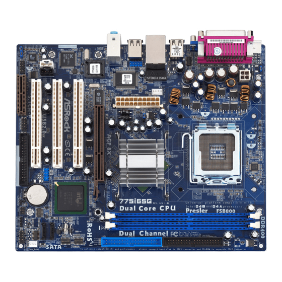
Page 2: Motherboard Layout
Floppy Connector (FLOPPY1) North Bridge Controller Serial Port Connector (COM1) CPU Fan Connector (CPU_FAN1) AMR Slot (AMR1) 184-pin DDR DIMM Slots (DDR1- 2) Front Panel Audio Header (AUDIO1) Secondary IDE Connector (IDE2, Black) JR1 / JL1 Jumpers Primary IDE Connector (IDE1, Blue) -
Page 3: Asrock I/O Plus
USB 2.0 Ports (USB01) RJ-45 Port USB 2.0 Ports (USB23) Line In (Light Blue) VGA Port Line Out (Lime) PS/2 Keyboard Port (Purple) Microphone (Pink) PS/2 Mouse Port (Green) Shared USB 2.0 Ports (USB45) 3 3 3 3 3 ASRock 775i65G Motherboard... -
Page 4: Package Contents
This Quick Installation Guide contains introduction of the motherboard and step-by- step installation guide. More detailed information of the motherboard can be found in the user manual presented in the Support CD. Because the motherboard specifications and the BIOS software might be updated, the content of this manual will be subject to change without notice. -
Page 5: Specifications
Specifications Specifications Specifications Specifications Specifications Platform - Micro ATX Form Factor: 9.6-in x 8.0-in, 24.4 cm x 20.3 cm ® - LGA 775 for Intel Core 2 Extreme / Core 2 Duo / ® ® ® ® Pentium XE / Pentium... - Page 6 - CD in header - AUX in header - Front panel audio connector - 2 x USB 2.0 headers (support 4 USB 2.0 ports; 2 of them are shared with USB4_5) (see CAUTION 9) BIOS Feature - 4Mb AMI BIOS - AMI Legal BIOS - Supports “Plug and Play”...
- Page 7 To improve heat dissipation, remember to spray thermal grease between the CPU and the heatsink when you install the PC system. Do NOT use a 3.3V AGP card on the AGP slot of this motherboard! It may cause permanent damage! ®...
-
Page 8: Pre-Installation Precautions
Before you insert the 775-LAND CPU into the socket, please check if the CPU surface is unclean or if there is any bent pin on the socket. Do not force to insert the CPU into the socket if above situation is found. - Page 9 775-LAND CPU For proper inserting, please ensure to match the two orientation key notches of the CPU with the two alignment keys of the socket. Step 2-3. Carefully place the CPU into the socket by using a purely vertical motion.
-
Page 10: Installation Of Cpu Fan And Heatsink
1. It is recommended to use the cap tab to handle and avoid kicking off the PnP cap. 2. This cap must be placed if returning the motherboard for after service. Step 4. Close the socket: Step 4-1. Rotate the load plate onto the IHS. -
Page 11: Installation Of Memory Modules (Dimm)
Unlock a DIMM slot by pressing the retaining clips outward. Step 2. Align a DIMM on the slot such that the notch on the DIMM matches the break on the slot. The DIMM only fits in one correct orientation. It will cause permanent damage to the motherboard and the DIMM if you force the DIMM into the slot at incorrect orientation. -
Page 12: Expansion Slots (Pci, Agp And Amr Slots)
PCI slots: The PCI slots are used to install expansion cards that have the 32-bit PCI interface. AGP slot: The AGP slot is used to install a graphics card. The ASRock AGP slot has a special design of clasp that can securely fasten the inserted graphics card. -
Page 13: Jumpers Setup
Note: To select +5VSB, it requires 2 Amp and higher standby current provided by power supply. (see p.2 No. 23) (see p.2 No. 23) Note: If the JL1 and JR1 jumpers are short, both the front panel and the rear panel audio connectors can work. Clear CMOS (CLRCMOS0, 2-pin jumper) 2-pin jumper (see p.2 No. -
Page 14: Onboard Headers And Connectors
FDD Connector (33-pin FLOPPY1) (see p.2 No. 19) the red-striped side to Pin1 Note: Make sure the red-striped side of the cable is plugged into Pin1 side of the connector. Primary IDE Connector (Blue) Secondary IDE Connector (Black) (39-pin IDE1, see p.2 No. 9) (39-pin IDE2, see p.2 No. - Page 15 ASRock I/O Plus provides you 6 ready-to-use USB 2.0 ports on (9-pin USB67) the rear panel. If the rear USB (see p.2 No. 18) ports are not sufficient, this USB 2.0 header is available to support 2 extra USB 2.0 ports.
- Page 16 Though this motherboard provides 4-Pin CPU fan (Quiet Fan) support, the 3-Pin CPU fan still can work successfully even without the fan speed control function. If you plan to connect the 3-Pin CPU fan to the CPU fan connector on this motherboard, please connect it to Pin 1-3.
- Page 17 STEP 3: Connect one end of the SATA data cable to the motherboard’s primary SATA connector (SATA1). STEP 4: Connect the other end of the SATA data cable to the primary SATA hard disk. If you just want to install only one SATA HDD, the installation process is complete at this step.
-
Page 18: Bios Information
Host Frequency” option of BIOS setup to [Auto], which will show you the actual CPU host frequency in the following item. Therefore, CPU FSB is untied during overclocking, but AGP / PCI bus is in the fixed mode so that FSB can operate under a more stable overclocking environment. - Page 19 1. Einführung 1. Einführung 1. Einführung Wir danken Ihnen für den Kauf des ASRock 775i65G Motherboard, ein zuverlässiges Produkt, welches unter den ständigen, strengen Qualitätskontrollen von ASRock gefertigt wurde. Es bietet Ihnen exzellente Leistung und robustes Design, gemäß der Verpflichtung von ASRock zu Qualität und Halbarkeit.
-
Page 20: Spezifikationen
Spezifikationen Spezifikationen Spezifikationen Spezifikationen Spezifikationen Plattform - Micro ATX-Formfaktor: 24.4 cm x 20.3 cm; 9.6 Zoll x 8.0 Zoll ® - LGA 775 für Intel Core 2 Extreme / Core 2 Duo / ® ® ® ® Pentium XE / Pentium... - Page 21 Beachten Sie bitte, dass Overclocking, einschließlich der Einstellung im BIOS, Anwenden der Untied Overclocking-Technologie oder Verwenden von Overclocking-Werkzeugen von Dritten, mit einem gewissen Risiko behaftet ist. Overclocking kann sich nachteilig auf die Stabilität Ihres Systems auswirken oder sogar Komponenten und Geräte Ihres Systems beschädigen.
- Page 22 Shutdown durch. Bevor Sie das System neu starten, prüfen Sie bitte, ob der CPU-Lüfter am Motherboard richtig funktioniert, und stecken Sie bitte den Stromkabelstecker aus und dann wieder ein. Um die Wärmeableitung zu verbessern, bitte nicht vergessen, etwas Wärmeleitpaste zwischen CPU und Kühlkörper zu sprühen.
- Page 23 Bevor Sie die 775-Pin CPU in den Sockel sitzen, prüfen Sie bitte, ob die CPU-Oberfläche sauber ist und keine der Kontakte verbogen sind. Setzen Sie die CPU nicht mit Gewalt in den Sockel, dies kann die CPU schwer beschädigen. ASRock 775i65G Motherboard...
- Page 24 Pin1 Orientierungskerbe Orientierungskerbe 775-Pin Sockel 775-Pin CPU Um die CPU ordnungsgemäß einsetzen zu können, richten Sie die zwei Orientierungskerben der CPU mit den beiden Markierungen des Sockels aus. Schritt 2-3. Drücken Sie die CPU vorsichtig in vertikaler Richtung in den Sockel.
- Page 25 Kappe drücken, um ein Entfernen zu erleichtern. 1. Verwenden Sie beim Entfernen die Kappenlasche und vermeiden Sie ein Abreißen der PnP-Kappe. 2. Diese Kappe muss angebracht werden, falls Sie das Motherboard zur Reparatur bringen. Schritt 4. Sockel schließen: Schritt 4-1. Drehen Sie die Ladeplatte auf den Kühlkörper (IHS).
- Page 26 Installation des CPU-Lüfters und Kühlkörpers Für Installationshinweise, siehe Betriebsanleitung Ihres CPU-Lüfters und Kühlkörpers. Unten stehend ein Beispiel zur Installation eines Kühlkörpers für den 775-Pin CPU. Schritt 1. Geben Sie Wärmeleitmaterial auf die Mitte (Tragen Sie Wärmeleitmaterial auf. ) des IHS, auf die Sockeloberfläche.
- Page 27 Öffnen Sie einen DIMM-Slot, indem Sie drücken. Schritt 2: Richten Sie das DIMM-Modul so über dem Slot aus, dass das Modul mit der Kerbe in den Slot passt. Die DIMM-Module passen nur richtig herum eingelegt in die Steckplätze. Falls Sie versuchen, die DIMM-Module mit Gewalt falsch herum in die Steckplätze zu zwingen, führt dies zu dauerhaften...
- Page 28 2.4 Er 2.4 Er weiterungssteckplätze: (PCI-, A -, und AMR -Slots): Es stehen 3 PCI-, 1 AGP-, und 1 AMR-Slot auf dem 775i65G Motherboard zur Verfügung. PCI-Slots: PCI-Slots werden zur Installation von Erweiterungskarten mit dem 32bit PCI-Interface genutzt. AGP-Slot: Der AGP-Steckplatz dient zur Installation einer Grafikkarte. Der ASRock AGP-Steckplatz hat speziell entwickelte Klammern, die die eingefügte Grafikkarte sicher festhalten.
-
Page 29: Einstellung Der Jumper
(siehe S.2 - Nr. 1) und die PS/2 oder USB- Weckfunktionen zu aktivieren. Hinweis: Um +5VSB nutzen zu können, muss das Netzteil auf dieser Leitung 2A oder mehr leisten können. (siehe S.2 - Nr. 23) (siehe S.2 - Nr. 23) Hinweis: Sind die Jumper JL1 und JR1 gesetzt funktionieren beide Audioanschlüsse, Front- und Rückseite. - Page 30 Floppy-Laufwerk (33-Pin FLOPPY1) die rotgestreifte Seite auf Stift 1 (siehe S.2 - Nr. 19) Hinweis: Achten Sie darauf, dass die rotgestreifte Seite des Kabel mit der Stift 1- Seite des Anschlusses verbunden wird. Primärer IDE-Anschluss (blau) Sekundärer IDE-Anschluss (schwarz) (39-pin IDE1, siehe S.2 - Nr. 9) (39-pin IDE2, siehe S.2 - Nr.
- Page 31 Serial ATA- (SATA-) Sie können beide Enden des Datenkabel SATA-Datenkabels entweder mit der SATA-Festplatte oder dem (Option) SATA-Anschluss am Mainboard verbinden. Serial ATA- (SATA-) Verbinden Sie das schwarze Stromversorgungskabel Ende des SATA-Netzkabels mit dem Netzanschluss am Laufwerk. (Option) Verbindung zum Verbinden Sie dann das weiße...
- Page 32 Anschlussmöglichkeit und Kontrolle über Audio-Geräte. 1. +5VA wird nur zur Audio-Stromversorgung verwendet. Bitte schließen Sie diesen Anschluss nicht an andere stromführende Geräte, wie USB- Geräte an. 2. Das HD- (Azalia) Frontaudio-Anschlussfeld und das AC’97-Frontaudio- Anschlussfeld verfügen über unterschiedliche Pinbelegungen. Der falsche Anschluss von Frontaudio-Anschlussfeld und Frontaudio-Anschlussleiste kann dauerhafte Schäden am Motherboard verursachen.
- Page 33 Obwohl dieses Motherboard einen vierpoligen CPU-Lüfteranschluss (Quiet Fan) bietet, können auch CPU-Lüfter mit dreipoligem Anschluss angeschlossen werden; auch ohne Geschwindigkeitsregulierung. Wenn Sie einen dreipoligen CPU-Lüfter an den CPU-Lüferanschluss dieses Motherboards anschließen möchten, verbinden Sie ihn bitte mit Pins 1–3 anschließen den Pins 1 –...
- Page 34 Anschließend werden die mit Ihrem System kompatiblen Treiber automatisch erkannt und auf dem Bildschirm angezeigt. Zur Installation der nötigen Treiber gehen Sie bitte der Reihe nach von oben nach unten vor. Nur so können die von Ihnen installierten Treiber richtig arbeiten.
- Page 35 CPU Host-Frequenz beim folgenden Eintrag angezeigt. Der CPU-FSB wird dadurch beim Übertakten freigegeben, allerdings befindet sich der AGP / PCI-Bus in einem fixierten Modus, so dass der FSB in einer stabileren Übertaktungsumgebung arbeiten kann. Beziehen Sie sich auf die Warnung vor möglichen Overclocking-Risiken auf Seite 21, bevor Sie die Untied Overclocking-Technologie anwenden.
- Page 36 Site web ASRock, http://www.asrock.com 1.1 Contenu du paquet Carte mère ASRock 775i65G (Facteur de forme Micro ATX : 9.6 pouces x 8.0 pouces, 24.4 cm x 20.3 cm) Guide d’installation rapide ASRock 775i65G CD de soutien ASRock 775i65G Un câble ruban IDE Ultra ATA 66/100 80 conducteurs Un câble ruban pour un lecteur de disquettes 3,5 pouces...
-
Page 37: Spécifications
- ASRock U-COP (voir ATTENTION 7) - Garde d’échec au démarrage (B.F.G.) Slot d’extension - 3 x slots PCI - 1 x slot AGP, support des cartes AGP 1.5V, 8X / 4X (voir ATTENTION 8) - 1 x slot AMR VGA sur carte - Intel ®... - Page 38 - br. 4 connecteur d’alimentation 12V ATX - Connecteurs audio internes - Connecteur audio panneau avant - 2 x En-tête USB 2.0 (Supporte 4 ports USB 2.0 ; 2 de ces ports sont partagés avec USB4_5) (voir ATTENTION 9) BIOS...
- Page 39 ATTENTION Il est important que vous réalisiez qu’il y a un certain risque à effectuer l’overclocking, y compris ajuster les réglages du BIOS, appliquer la technologie Untied Overclocking, ou utiliser des outils de tiers pour l’overclocking. L’overclocking peut affecter la stabilité de votre système, ou même causer des dommages aux composants et dispositifs de votre...
- Page 40 A chaque désinstallation de composant, placez-le sur un support antistatique ou dans son sachet d’origine. Lorsque vous placez les vis dans les orifices pour vis pour fixer la carte mère sur le châssis, ne serrez pas trop les vis ! Vous risquez sinon d’endommager la carte mère.
- Page 41 Socket 775 broches Processeur 775 broches Pour une insertion correcte, veuillez vérifier que vous faites bien correspondre les deux encoches d’orientation sur le processeur avec les deux détrompeurs du socket Etape 2-3. Mettez soigneusement en place le processeur dans le socle en un mouvement strictement vertical.
- Page 42 1. Il est recommandé d’utiliser la languette du capuchon ; évitez de faire sortir le capuchon PnP. 2. Ce capuchon doit être mis en place si vous renvoyez la carte mère pour service après vente. Etape 4. Refermez le socle : Etape 4-1.
- Page 43 Si vous enfoncez les attaches sans les faire tourner dans le sens des aiguilles d’une montre, le dissipateur thermique ne sera pas fixé sur la carte mère. Etape 5. Connectez l’en-tête du ventilateur sur le connecteur pour ventilateur de processeur sur la carte mère.
-
Page 44: Installation D'une Carte D'extension
2.4 Slot d’extension (Slots PCI, AGP, et AMR) 2.4 Slot d’extension (Slots PCI, AGP, et AMR) IIl y a 3 slots PCI, 1 slot AGP, et 1 slot AMR sur les cartes mères 775i65G. Slots PCI: Les slots PCI sont utilisés pour installer des cartes d’extension dotées d’une interface PCI 32 bits. - Page 45 Note: Pour sélectionner +5VSB, il faut obligatoirement 2 Amp et un courant standby supérieur fourni par l’alimentation. (voir p.2 No. 23) (voir p.2 No. 23) Note: Si les cavaliers JL1 et JR1 sont reliés, les connecteurs audio du panneau avant et du panneau arrière peuvent fonctionner. Effacer la CMOS (CLRCMOS0, le cavalier le cavalier à...
- Page 46 (FLOPPY1 br. 33) le côté avec fil rouge côté Broche1 (voir p.2 No. 19) Note: Assurez-vous que le côté avec fil rouge du câble est bien branché sur le côté Broche1 du connecteur. Connecteur IDE primaire (bleu) Connecteur IDE secondaire (noir) (39-pin IDE1, voir p.2 No.
- Page 47 électrique. En-tête USB 2.0 ASRock I/O Plus vous apporte 6 ports USB 2.0 par défaut sur (USB67 br.9) le panneau arrière. Si le nombre (voir p.2 No. 18) des ports USB à l’arrière n’est pas suffisant, cette En-tête USB 2.0 (USB67) permet de...
- Page 48 (voir p.2 No. 22) audio. 1. + 5VA n’est utilisé que pour l’alimentation audio, veuillez ne pas la brancher à toute autre alimentation, tel que l’USB. 2. Le panneau frontal audio HD (Azalia) et le panneau frontal audio AC’97 ont des définitions de broches différentes-.
- Page 49 (Ventilateur silencieux) ventilateur de CPU à 4 broches , le ventilateur de CPU à 3 broches peut bien fonctionner même sans la fonction de commande de vitesse du ventilateur. Si vous prévoyez de connecter le ventilateur de CPU à...
- Page 50 Puis, les pilotes compatibles avec votre système peuvent être détectés automatiquement et sont listés sur la page du pilote du CD. Veuillez suivre l’ordre de haut en bas sur le côté pour installer les pilotes requis. En conséquence, les pilotes que vous installez peuvent fonctionner correctement.
- Page 51 Windows ® 98 SE / ME / 2000 / XP. Le CD technique livré avec cette carte mère contient les pilotes et les utilitaires nécessaires pour améliorer les fonctions de la carte mère. Pour utiliser le CD technique, insérez-le dans le lecteur de CD-ROM. Le Menu principal s’affiche automatiquement si “AUTORUN”...
-
Page 52: Contenuto Della Confezione
Grazie per aver scelto una scheda madre ASRock 775i65G, una scheda madre affidabile prodotta secondo i severi criteri di qualità ASRock. Le prestazioni eccellenti e il design robusto si conformano all’impegno di ASRock nella ricerca della qualità e della resistenza. - Page 53 - Boot Failure Guard (B.F.G.) Slot di - 3 x slot PCI espansione - 1 x slot AGP, supporta scheda AGP a 1.5V, modelli 8X / 4X (vedi ATTENZIONE 8) - 1 x slot AMR ® VGA su scheda - Intel Extreme Graphics 2 integrato - VGA DirectX 8.0...
- Page 54 - 20-pin collettore alimentazione ATX - 4-pin connettore ATX 12V - Connettori audio interni - Connettore audio sul pannello frontale - 2 x Collettore USB 2.0 (supporto di 4 porte USB 2.0, 2 delle quali condivise con USB4_5) (vedi ATTENZIONE 9) BIOS...
- Page 55 Per migliorare la dissipazione del calore, ricordare di applicare l’apposita pasta siliconica tra il processore e il dissipatore quando si installa il sistema. NON usare schede AGP da 3,3 V nello slot AGP di questa motherboard! Ciò potrebbe provocare danni permanenti! ®...
-
Page 56: Installazione
3. Tenere i componenti per i bordi e non toccare i ICs. 4. Ogni volta che si disinstalla un componente, appoggiarlo su un tappetino antistatico messo a terra o depositarlo nella borsa data in dotazione con il componente. - Page 57 Vista del socket 775-Pin Prima da inserire la CPU da 775-Pin nel socket, verificare che la superficie della CPU sia pulita e che non ci siano pin piegati nel socket. Non forzare l’inserimento della CPU nel socket se ci sono pin piegati.
- Page 58 1. Si raccomanda di utilizzare la linguetta del cappuccio per la manipolazione ed evitare di far saltare via il cappuccio PnP. 2. Questo tappo deve essere inserito se se la scheda madre deve essere restituita per l’assistenza. Fase 4. Chiudere la presa: Fase 4-1.
- Page 59 Ripetere la stessa operazione con gli altri fastener. Se si premono i fastener verso il basso, senza ruotarli in senso orario, il dissipatore non viene fissato bene alla scheda madre Fase 5. Collegare il cavo di alimentazione della ventola al connettore ventola della CPU sulla scheda madre.
- Page 60 2.3 Installazione dei moduli di memoria (DIMM) 2.3 Installazione dei moduli di memoria (DIMM) La motherboard 775i65G dispone di due slot DIMM DDR (Double Data Rate) a 184 pin e supporta la tecnologia Dual Channel Memory. Per attivare la configurazione Dual Channel Memory bisogna installare sempre due moduli di memoria identici (stessa marca, velocità, dimensioni e tipo di chip) negli slot DIMM.
- Page 61 2.4 Slot di espansione (Slot PCI, Slot AGP, e Slot AMR) 2.4 Slot di espansione (Slot PCI, Slot AGP, e Slot AMR) Esistono 3 slot PCI, 1 slot AGP, e 1 slot AMR su entrambe le schede madri 775i65G. Slot PCI: Sono utilizzati per installare schede di espansione con Interfaccia PCI a 32-bit.
- Page 62 Nota: Per selezionare +5VSB, si richiedono almeno 2 Ampere e il consumo di corrente in standby sarà maggiore. (vedi p.2 Nr. 23) (vedi p.2 Nr. 23) Nota: Se i jumper JL1 e JR1 sono chiusi, funzionano sia i connettori audio frontali che posteriori. Resettare la CMOS (CLRCMOS0, jumper a 2 pin) jumper a 2 pin (vedi p.2 Nr.
- Page 63 Floppy disk (33-pin FLOPPY1) Lato del Pin1 con la striscia rossa (vedi p.2 Nr. 19) Nota: Assicurarsi che il lato del cavo con la striscia rossa sia inserito nel lato Pin1 del connettore. Connettore IDE primario (blu) Connettore IDE secondario (nero) (39-pin IDE1, vedi p.2 Nr.
- Page 64 USB 2.0 aggiuntive. Collettore USB 2.0 Questo collettore USB4_5 è condiviso condiviso con le porte USB 2.0 4 e 5 su ASRock I/O Plus™. (9-pin USB4_5) Quando si utilizzano le porte (vedi p.2 Nr. 29) USB del pannello frontale,...
- Page 65 1. +5VA viene utilizzato solo per alimentazione audio. Non collegarlo ad altre fonti di alimentazione, ad esempio USB. 2. Il pannello anteriore audio HD (Azalia) e quello AC’97 dispongono di una differente definizione pin. Un collegamento non adeguato del pannello anteriore audio e del suo connettore potrebbe causare danni permanenti a questa scheda madre.
- Page 66 Sebbene la presente scheda madre disponga di un supporto per ventola CPU a 4 piedini (ventola silenziosa), la ventola CPU a 3 piedini è in grado di funzionare anche senza la funzione di controllo della velocità della ventola. Se si intende collegare la ventola CPU a 3 piedini al connettore della ventola CPU su questa scheda madre, collegarla ai piedini 1-3.
-
Page 67: Installazione Di Hard Disk Ata Seriali
Questa sezione illustra come installare hard disk SATA. 1° PASSO: Installare gli Hard Disk SATA negli spazi per le unità disco del telaio. 2° PASSO: Collegare il cavo d’alimentazione SATA al disco rigido SATA. 3° PASSO: Collegare una estremità del cavo dati SATA al connettore SATA principale della scheda madre (SATA1). - Page 68 ® : 98 SE / ME / 2000 / XP. Il CD di supporto a corredo della scheda madre contiene i driver e utilità necessari a potenziare le caratteristiche della scheda. Inserire il CD di supporto nel lettore CD-ROM. Se la funzione “AUTORUN” è attivata nel computer, apparirà...
-
Page 69: Contenido De La Caja
ASRock. Esta Guía rápida de instalación contiene una introducción a la placa base y una guía de instalación paso a paso. Puede encontrar una información más detallada sobre la placa base en el manual de usuario incluido en el CD de soporte. - Page 70 Especificación Especificación 1.2 Especificación Especificación Especificación Plataforma - Factor forma Micro ATX: 24,4 cm x 20.3 cm, 9,6” x 8,0” Procesador - LGA 775 para Intel ® Core 2 Extreme / Core 2 Duo / Pentium ® XE / Pentium ®...
- Page 71 - 4-pin conector de ATX 12V power - Conector de Audio Interno - Conector de audio de panel frontal - 2 x Cabezal USB 2.0 (soporta 4 puertos USB 2.0; 2 de ellos son compartidos con USB 4_5) (vea ATENCIÓN 9)
- Page 72 ADVERTENCIA Tenga en cuenta que hay un cierto riesgo implícito en las operaciones de aumento de la velocidad del reloj, incluido el ajuste del BIOS, aplicando la tecnología de aumento de velocidad liberada o utilizando las herramientas de aumento de velocidad de otros fabricantes.
-
Page 73: Instalación
4. Ponga cualquier componente deslocalizado sobre la bolsa anti- estástica que viene con la placa madre. 5. Al colocar los tornillos en sus agujeros para fijar la placa madre en el chasis, no los apriete demasiado. Eso podría dañar la placa madre. - Page 74 Antes de insertar la CPU de 775 agujas en el socket, compruebe que la superficie de la CPU se encuentra limpia y no hay ninguna aguja torcida en el socket. No introduzca la CPU en el socket por la fuerza si se produce la situación anterior. Si lo hace, puede producir daños graves en la CPU.
- Page 75 Para una correcta instalación, consulte los manuales de instrucciones del ventilador y el disipador de la CPU. A continuación se ofrece un ejemplo para ilustrar la instalación del disipador para la CPU de 775 agujas. (Aplique el material termal de interfaz) Paso 1.
- Page 76 Repita el proceso con los cierres restantes. Si presiona los cierres sin girarlos en el sentido de las agujas del reloj, el disipador no se podrá fijar a la placa madre. Paso 5. Conecte el cabezal del ventilador con el conector del ventilador de la CPU en la placa madre.
-
Page 77: Instalación De Memoria
Asegúrese de desconectar la fuente de alimentación antes de añadir o retirar módulos DIMM o componentes del sistema. Paso 1. Empuje los clips blancos de retención por el extremo de cada lado de la ranura de memoria. Paso 2. Encaje la muesca del DIMM hacia la cumbrera de la ranura. - Page 78 Paso 2. Quite la tapa que corresponde a la slot que desea utilizar. Paso 3. Encaje el conector de la tarjeta a la slot. Empuje firmemente la tarjeta en la slot. Paso 4. Asegure la tarjeta con tornillos.
- Page 79 (ver p.2, N. 23) (ver p.2, N. 23) Atención: Si los puentes JL1 y JR1 son cortos, tanto el conector de audio del panel frontal como del panel posterior pueden funcionar. Limpiar CMOS (CLRCMOS0, jumper de 2 pins) (ver p.2, N.
-
Page 80: Cabezales Y Conectores En Placas
(ver p.2 N. 19) la banda roja debe quedar en el mismo lado que el contacto 1 Atención: Asegúrese que la banda roja del cable queda situado en el mismo lado que el contacto 1 de la conexión. IDE conector primario (azul) IDE conector secundario (negra) (39-pin IDE1, ver p.2 N. - Page 81 USB del panel (ver p.2, N. 29) frontal conectando el cable USB del panel frontal a este cabezal (USB4_5), los puertos USB 4 y 5 en el ASRock I/O Plus no funcionarán. Conector de módulo Infrared Soporta módulo Infrared de transmisión y recepción...
- Page 82 1. Se utilizan +5VA como potencia de sonido. No lo conecte a ninguna otra fuente de alimentación, como el USB. 2. El panel frontal de sonido HD (Azalia) y el panel frontal de sonido AC’97 tienen diferentes definiciones de conexión. La conexión incorrecta del panel frontal y la cabecera frontal de sonido puede dañar esta placa...
- Page 83 Conector de ATX 12V power Tenga en cuenta que es necesario conectar este (4-pin ATX12V1) conector a una toma de corriente (ver p.2, N. 2) con el enchufe ATX 12V, de modo que proporcione suficiente electricidad. De lo contrario no se podrá...
-
Page 84: Instalación De Discos Duro Ata Serie
PASO 2: Conecte el cable de alimentación SATA al disco duro SATA. PASO 3: Conecte un extremo del cable de datos SATA al conector SATA primario de la placa base (SATA1). PASO 4: Conecte el otro extremo del cable de datos SATA al disco duro SATA primario. -
Page 85: Tecnología De Forzado De Reloj No Relacionado
® : 98SE / ME / 2000 / XP El CD de instalación que acompaña la placa-base trae todos los drivers y programas utilitarios para instalar y configurar la placa-base. Para iniciar la instalación, ponga el CD en el lector de CD y se desplegará el Menú...