Advertisement
Quick Links
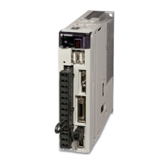
SGDV-@
Sigma-5 servo drive
The High perfomance servo family for motion
control. Compact size, reduced space and
integrated MECHATROLINK-II.
• Advance autotuning function
• Enhanced vibration supression function
• Standard support for analog voltage/pulse train ref-
erence series or MECHATROLINK-II communica-
tions reference series.
• Support for direct drive servomotors, linear servo-
motors and linear sliders
• Integrated safety stop function
• Oscilloscope available via software tool
• Windows based configuration and commissioning
software
Ratings
• 230 VAC Single-phase 50 W to 1.5 kW (4.77 Nm)
• 400 VAC Three-phase 500 W to 15 kW (95.4 Nm)
System configuration
(Refer to chapter Sigma-II rotary motors)
SGMGH, SGMUH, SGMSH,
SGMAH, SGMPH
SGMBH Servo Motor
Servo Motor
(Refer to chapter Sigma-5 rotary motors)
SGMJV, SGMAV, SGMEV
SGMGV, SGMSV
Servo Motor
Servo Motor
(Refer to chapter Sigma linear motors)
SGLG_ linear
SGLF_ linear
Servo Motor
Servo Motor
(Refer to chapter Sigma direct drive motors)
Direct drive servo motor
Direct drive servo motor
SGMCS-@-@M, N
SGMCS-@-@B, C, D, E
Sigma-5 servo drive
Sigma-5 Analog/Pulse Reference Servo Drive
Sigma-5 MECHATROLINK-II Servo Drive
SGLT_ linear
Servo Motor
CN5
Analog monitor cable
USB cable
CN7
CN1
General purpose cable
CN8
CN2
Safety cable
Battery case for absolute encoder
CN5
Analog monitor cable
CN6
MECHATROLINK-II network
USB cable
CN7
CN1
General purpose connector
CN8
Safety cable
CN2
Battery case for absolute encoder
Personal
computer
Position control unit
Terminal block
position control
Unit
Personal
computer
1
Advertisement

Related Manuals for Omron SIGMA-5 SERVO DRIVE


Summary of Contents for Omron SIGMA-5 SERVO DRIVE
- Page 1 • Oscilloscope available via software tool • Windows based configuration and commissioning software Ratings • 230 VAC Single-phase 50 W to 1.5 kW (4.77 Nm) • 400 VAC Three-phase 500 W to 15 kW (95.4 Nm) System configuration Sigma-5 Analog/Pulse Reference Servo Drive...
- Page 2 230 V (1 phase) 400 V (3 phase) 400 V (3 phases) Analog/Pulse MECHATROLINK-II Analog/Pulse MECHATROLINK-II Sigma-II series motors (refer to the Sigma-II rotary motors chapter for details) SGMAH (3000 min 230 V 0.0955 Nm 30 W SGDV-A5A01A-OY SGDV-A5A11A-OY 0.159 Nm...
- Page 3 SGDV-30D01A-OY SGDV-30D11A-OY 12.6 Nm 4 kW SGDV-50D01A-OY SGDV-50D11A-OY 15.8 Nm 5 kW SGDV-50D01A-OY SGDV-50D11A-OY Sigma direct drive motors (refer to the Sigma direct drive motors chapter for details) SGMCS (200 min 230 V 2.0 Nm 42 W SGDV-04A01A-OY SGDV-04A11A-OY 5.0 Nm...
-
Page 4: Type Designation
Max. output current Arms 16.9 Input power Main circuit Single-phase, 200 to 230 VAC + 10 to -15% (50/60 Hz) Supply Control circuit Single-phase, 200 to 230 VAC + 10 to -15% (50/60 Hz) Control method Single phase full-wave rectification / IGBT / PWM / sine-wave current drive method... -
Page 5: General Specifications
Servo alarm, alarm codes (3-bit output): CN1 output terminal is fixed It is possible to output three types of signal form incl.: positioning complete, speed coincidence detection, servo- motor rotation detection, servo ready, current limit detection, speed limit detection, brake release, warning, NEAR. - Page 6 /CLR Note: 1. Pin numbers in parentheses () indicate signal grounds. 2. The functions allocated to /S-ON, /P-CON. P-OT, N-OT, /ALM-RST, /P-CL, and /N-CL input signals can be changed by using the parameters. 3. The voltage input range for speed and torque references is a maximum of ±12 V.
-
Page 7: Terminal Specifications
Note: 1. Pin numbers in parentheses () indicate signal grounds. 2. The functions allocated to /TGON, /S-RDY, and /V-CMP (/COIN) output signals can be changed by using the parameters. /CLT, /VLT, / BK, /WARN and /NEAR signals can also be changed. - Page 8 Note: 1. The functions allocated to /DEC, P-OT, N-OT, /EXT1,-/EXT2 and /EXT3 input signals can be changed by using the parameters. 2. If the Forward/ Reverse run prohibited function is used, the software can be used to stop the Servo drive. If the application does not satisfy the requirements, add an external circuit for safety reasons as required.
- Page 9 Note: Set the parameter to allocate a function. /SO3+ /SO3- Signal ground: Connected to frame ground if the shield wire of the I/O signal cable is connected to the connector shell. Phase-A signal Dividing ratio can be set by parameter /PAO...
-
Page 10: Operation
Operating (servo on) To change modes, press the MODE/SET key. Forward rotation prohibited (forward overtravel) Reverse rotation prohibited (reverse overtravel) Hard Wire Base Block. Servo drive is baseblocked by the safe- h.bb Power ON ty function Mode test without motor (Display example) Alarm. - Page 11 Dimensions Sigma-5 Analog/Pulse Reference Servo Drive SGDV-A5A0@A-OY to -02A0@A-OY (230 V, 50 to 200 W) (17) 2-M4 Screw Holes Cooling Fan Nameplate Servo drive Rear View Two Terminals Ground Terminal (25) 2-M4 Screws (75) Mounting Hole Diagram SGDV-04A0@A-OY (230 V, 400 W)
- Page 12 Air Flow 2-M4 Screws (Mounting Pitch) (75) Mounting Hole Diagram (40) Cooling Fan Terminal 14-M4 Screws SGDV-05D0@A-OY to -15D0@A-OY (400 V, 0.5 to 1.5 kW) (17) 4-M4 Screw Holes Nameplate Servo drive Rear View Two Terminals 50±0.5 (Mounting Pitch) (25) 23 24.5...
- Page 13 SGDV-20/30D0@A-OY (400 V, 2/3 kW) 4-M5 Screw Holes (17) Servo drive Nameplate Rear View 24.5 50±0.5 Ground Terminal (Mounting Pitch) (75) 2-M4 Screws Mounting Hole Diagram (40) Cooling Fan Terminal 14-M4 Screws Terminal Details SGDV-50D0@A-OY (400 V, 5 kW) Cooling Fan...
- Page 14 SGDV-210D0@A to 260D0@A (400 V, 6 to 7.5 kW) Input Voltage 46 -M Screw Holes ( 17 ) Model CN 3 CN 7 CN 1 CN 8 CN 2 Servo drive Terminal Rear View 46 -M Screws Terminal 66 -M Screws ±...
- Page 15 Sigma-5 MECHATROLINK-II Servo Drives SGDV-A5A1@A-OY to -02A1@A-OY (230 V, 50 to 200 W) Cooling Fan 2-M4 Screw Holes Nameplate Servo drive Rear View Two Terminals Ground Terminal 2-M4 Screws (25) (75) Mounting Hole Diagram SGDV-04A1@A-OY (230 V, 400 W) Cooling Fan...
- Page 16 Air Flow 2-M4 Screws (Mounting Pitch) (75) Mounting Hole Diagram (40) Cooling Fan Terminal 14-M4 Screws SGDV-05D1@A-OY to -15D1@A-OY (400 V, 0.5 to 1.5 kW) 4-M4 Screw Holes Model Nameplate Two Terminals Servo drive Rear View ± Ground Terminal (25)
- Page 17 SGDV-20/30D1@A-OY (400 V, 2/3 kW) 4-M5 Screw Holes Model Servo drive Nameplate Rear View ± Ground Terminal 2-M4 Screws (Mounting Pitch) (75) Mounting Hole Diagram (40) Cooling Fan Terminal 14-M4 Screws Terminal Details SGDV-50D1@A-OY (400 V, 5 kW) Cooling Fan...
- Page 18 SGDV-210D1@A to 260D1@A (400 V, 6 to 7.5 kW) 46 -M Screw Holes Input Voltage ( 7 ) Model CN 6 CN 3 CN 7 CN 1 CN 8 CN 2 Servo drive Rear View Terminal 46 -M Screws Terminal 66 -M Screws ±...
- Page 19 4 x M4 CABLE SIZE 0 to 6 mm output flexes 16AWG strip 7 mm (1) Connect to the servodrive ground in case not footprint installation 3 x 350mm with ferrules CABLE SIZE 0 to 6 mm M5 Earth Stud...
- Page 20 *3 Regenerative resistor can be connected between B1 and B2. For 750 W servo drives types normally short B2 and B3. *4 For servo ON, connect to safety device and set wiring to enable safety function. When not using the safety function, use the servo drive with the plug (JZSP-CVH05-E, provided as an accessory) inserted into the CN8.
- Page 21 B1 and B2. *4 For servo ON, connect to safety device and set wiring to enable safety function. When not using the safety function, use the servo drive with the plug (JZSP-CVH05-E, provided as an accessory) inserted into the CN8.
- Page 22 *2 Regenerative resistor can be connected between B1 and B2. For 750 W servo drives types normally short B2 and B3. *3 For servo ON, connect to safety device and set wiring to enable safety function. When not using the safety function, use the servo drive with the plug (JZSP-CVH05-E, provided as an accessory) inserted into the CN8.
- Page 23 B1 and B2. *3 For servo ON, connect to safety device and set wiring to enable safety function. When not using the safety function, use the servo drive with the plug (JZSP-CVH05-E, provided as an accessory) inserted into the CN8.
-
Page 24: Ordering Information
Servo Motor Servo Motor ABCDE Note: The symbols ... show the recommended sequence to select the components in a Sigma-5 servo system Servo motors, power & encoder cables Note: Refer to the servo motors chapter for detailed motor specifications and selection... - Page 25 1.5 kW SGDV-15A01A-OY SGMPH-15A@, SGMAV-10A@, SGMCS-45M@, SGMCS-80M@, SGMEV-15A@ SGMCS-80N@ SGDV-15A05A-OY SGLGW-90A200A@, SGLFW-50A380@, SGLFW-1ZA200@ 3 phase 0.5 kW SGDV-05D01A-OY SGMAH-03D@, SGMPH-04D@, 400 VAC SGMGH-05D@, SGMEV-04D@, SGMGV-05D@ SGDV-05D05A-OY - SGLFW-35D@ 1.0 kW SGDV-10D01A-OY SGMAH-07D@, SGMPH-08D@, SGMGH-09D@, SGMSH-10D@, SGMUH-10D@, SGMEV-08D@, SGMGV-09D@, SGMSV-10D@, SGDV-10D05A-OY -...
- Page 26 JZSP-BA01 USB Mini Connector cable JZSP-CVS06-02-E Note: when the encoder cables with a battery case are used, no battery is re- Note: doble shield USB cable recommended quired for CN1 (between pin 21 and 22). Battery for CN1 is ER6VCN3.
- Page 27 SGMCS-@-@B, C, D, E SGMCS-@-@M, N ABCDE Note: The symbols ... show the recommended sequence to select the components in a Sigma-5 servo system Servo motors, power & encoder cables Note: Refer to the servo motors chapter for detailed motor specifications and selection...
- Page 28 1.5 kW SGDV-15A11A-OY SGMPH-15A@, SGMAV-10A@, SGMCS-45M@, SGMCS-80M@, SGMEV-15A@ SGMCS-80N@ SGDV-15A15A-OY SGLGW-90A200A@, SGLFW-50A380@, SGLFW-1ZA200@ 3 phase 0.5 kW SGDV-05D11A-OY SGMAH-03D@, SGMPH-04D@, 400 VAC SGMGH-05D@, SGMEV-04D@, SGMGV-05D@ SGDV-05D15A-OY - SGLFW-35D@ 1.0 kW SGDV-10D11A-OY SGMAH-07D@, SGMPH-08D@, SGMGH-09D@, SGMSH-10D@, SGMUH-10D@, SGMEV-08D@, SGMGV-09D@, SGMSV-10D@, SGDV-10D15A-OY -...
- Page 29 Note: when the encoder cables with a battery case JUSP-BA01 are used, no bat- Note: doble shield USB cable recommended tery is required for CN1 (between pin 21 and 22). Battery for CN1 is ER6VCN3. Cable for Safety Functions (for CN8)
- Page 30 ALL DIMENSIONS SHOWN ARE IN MILLIMETERS. To convert millimeters into inches, multiply by 0.03937. To convert grams into ounces, multiply by 0.03527. Cat. No. I48E-EN-01 In the interest of product improvement, specifications are subject to change without notice. AC servo systems...