Advertisement
Quick Links
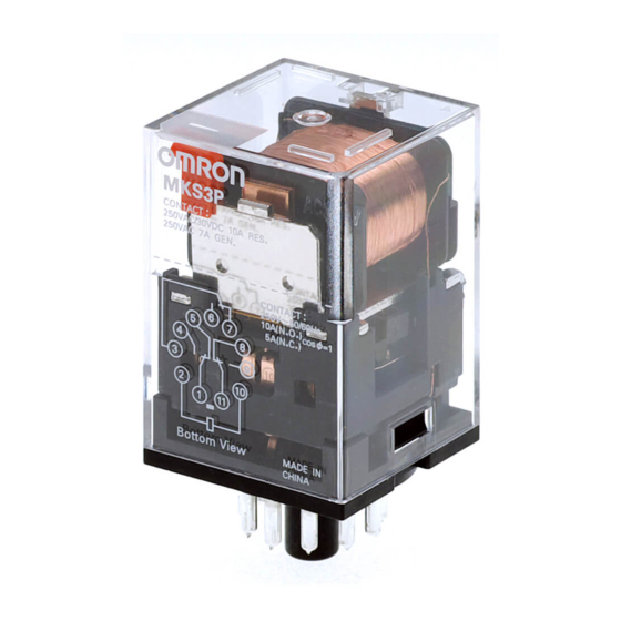
General-purpose Relay
MK-I/-S
Exceptionally Reliable General-purpose
Relay Features Mechanical Indicator/Push
Button
• Breaks relatively large load currents despite small size.
• Long life (minimum 100,000 electrical operations) assured by
silver contacts.
• Built-in operation indicator (Mechanical, LED), push button,
diode surge suppression, varistor surge suppression.
• Standard models are UL, CSA, SEV, DEMKO, NEMKO,
SEMKO, TÜV (IEC), and VDE.
• Conforming to CENELEC standards.
Model Number Structure
■ Model Number Legend
Standard Models
MK
-
-
1
2
3
4
5
1. Contact Form
2: DPDT
3: 3PDT
2. Cover
P: Dust cover
Special Accessories
MK
-
-
1
2
3
4
5
1. Contact Form
2:
DPDT
3:
3PDT
2. Cover
P:
Dust cover
3. Classification
N:
LED indicator
D:
Diode
V:
Varistor
ND: LED indicator and diode
NV: LED indicator and varistor
6
3. Internal Connection Construction
Blank: Standard
2 or 5: Non-standard connection
(Refer to Terminal Arrangement/
Internal Connections)
4. Mechanical Indicator Push Button
S:
Mechanical indicator and
push button
I:
Mechanical indicator
-
6
7
8
4. Coil Polarity
Blank: Standard
1:
Reverse
(Refer to Terminal Arrangement/
Internal Connections)
5. Internal Connection Construction
Blank: Standard
2 or 5: Non-standard connection
(Refer to Terminal Arrangement/
Internal Connections)
5. Approved Standards
Blank: UL, CSA, DEMKO, NEMKO
SEMKO, SEV, TÜV
VD:
VDE
6. Rated Voltage
(Refer to Coil Ratings)
6. Mechanical Indicator Push Button
S:
Mechanical indicator and
push button
I:
Mechanical indicator
7. Approved Standards
Blank: UL and CSA only
VD:
VDE (N and D models only)
8. Rated Voltage
(Refer to Coil Ratings)
MK-I/-S
General-purpose Relay
A-45
Advertisement

Related Manuals for Omron MK-I


Summary of Contents for Omron MK-I
- Page 1 MK-I/-S Exceptionally Reliable General-purpose Relay Features Mechanical Indicator/Push Button • Breaks relatively large load currents despite small size. • Long life (minimum 100,000 electrical operations) assured by silver contacts. • Built-in operation indicator (Mechanical, LED), push button, diode surge suppression, varistor surge suppression.
-
Page 2: Ordering Information
MK3PD-2-S-VD MK3PD-5-I-VD MK3PD-5-S-VD Note: 1. When ordering, add the rated voltage to the model number. Rated voltages are given in the coil ratings table in Specifications. Example: MK3P5-S 230 VAC Rated voltage 2. This DC coil comes in two types: standard coil polarity and reversed coil polarity. Refer to Terminal Arrangement/Internal Connections. -
Page 3: Specifications
3. ~ indicates AC and = indicates DC (IEC417 publications). 4. For 200 VDC applications, a 100-VDC Relay is supplied with a fixed 6.8 k , 30 W resistor. Be sure to connect the resistor in series with the coil. - Page 4 2,500 VAC, 50/60 Hz for 1 min between coil and contacts; 1,000 VAC, 50/60 Hz for 1 min between contacts of same polarity, terminals of the same polarity; 2,500 VAC, 50/60 Hz fro 1 min between current-carrying parts, non-current-carrying parts, and termi-...
- Page 5 10 A, 250 V~ (NO) (cos = 1) 100,000 cycles 6 to 240 V~ 5 A, 250 V~ (NC) (cos = 1) TÜV (VDE 0435 Teil 201/05’90, IEC 255 Teil 1-00/’75, EN 60950/’88 (TÜV File No.: R9051410) Coil ratings Contact ratings...
-
Page 6: Engineering Data
Engineering Data Electrical Endurance Maximum Switching Power AC resistive load 5,000 28-VDC resistive load 3,000 DC resistive load 250-VAC resistive load 28 VDC max. 120-VAC resistive load 1,000 AC inductive load 250-VAC inductive load 50 70 100 500 700 1,000... - Page 7 Note: Use the Surface-mounting Sockets (i.e., finger-protection models) with “-E” at the end of the model number. When using the PF083A and PF113A, be sure not to exceed the Socket’s maximum carry current of 5 A. Using at a current exceeding 5 A may lead to burning. Round terminals cannot be used for finger-protection models.
- Page 8 1000 (500)* * This dimension applies to the PFP-50N Mounting Track. * A total of twelve 25 x 4.5 elliptic holes is provided with six holes cut from each track end at a pitch of 10 mm. Mounting Height with Sockets...
- Page 9 Terminal Arrangement/Internal Connection (Bottom View) Standard MK2P-I, -S MK2P2-I, -S MK3P-I, -S MK3P2-I, -S MK3P5-I, -S (AC/DC Coil) VDE-approved Type MK2P-I-VD, -S-VD MK2P2-I-VD, -S-VD MK3P-I-VD, -S-VD MK3P2-I-VD, -S-VD MK3P5-I-VD, -S-VD (AC/DC Coil) ( ): Dual Numbering (12) (22) (12) (22) (11) (31)
- Page 10 LED Indicator Type MK2PN-I, -S MK2PN-2-I, -S MK3PN-I, -S MK3PN-2-I, -S MK3PN-5-I, -S (DC Coil: Standard Polarity) LED Indicator Type MK2PN1-I, -S MK2PN1-2-I, -S MK3PN1-I, -S MK3PN1-2-I, -S MK3PN1-5-I, -S (DC Coil: Reverse Polarity) Diode Type MK2PD-I, -S MK2PD-2-I, -S...
- Page 11 LED Indicator and MK2PNV-I, -S MK2PNV-2-I, -S MK3PNV-I, -S MK3PNV-2-I, -S MK3PNV-5-I, -S Varistor Type (AC Coil) VDE Approved Type MK2PN-I-VD, -3-VD MK2PN-2-I-VD, -3-VD MK3PN-I-VD, -S-VD MK3PN-2-I-VD, -S-VD MK3PN-5-I-VD, -S-VD LED Indicator Type (12) (22) (12) (22) (DC Coil: (11) (31)
- Page 12 (31) (11) ALL DIMENSIONS SHOWN ARE IN MILLIMETERS. To convert millimeters into inches, multiply by 0.03937. To convert grams into ounces, multiply by 0.03527. In the interest of product improvement, specifications are subject to change without notice. Cat. No. J011-E1-06...