Table of Contents
Advertisement
Quick Links
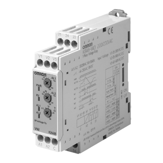
Single-phase Voltage Relay
K8AB-VW
Ideal for voltage monitoring for industrial
facilities and equipment.
• Monitor for overvoltages and undervoltages simultaneously.
Separate settings and outputs supported for overvoltages and
undervoltages.
• Manual resetting and automatically resetting supported by one
Relay.
• Pre-alarm Mode (H/HH and L/LL operating modes)
• Two SPDT output relays, 6 A at 250 VAC (resistive load).
• Process control signal (0 to 10 V) and current splitter input
supported.
• Relay warning status easily monitoring using LED indicator.
• Input frequency of 40 to 500 Hz supported.
• Easy wiring with ferrules
2 × 2.5 mm
solid or 2 × 1.5 mm
2
• CE mark compliance certified by third party.
UL certification pending.
Model Number Structure
■ Model Number Legend
K8AB-@@
1
2 3
4
1. Basic Model
K8AB:
Measuring and Monitoring Relays
2. Functions
VW:
Single-phase Voltage Relay (Simultaneous upper and lower limit monitoring)
3. Measuring Tension
1:
6 to 60 mV AC/DC, 10 to 100 mV AC/DC, 30 to 300 mV AC/DC
2:
1 to 10 V AC/DC, 3 to 30 V AC/DC, 15 to 150 V AC/DC
3:
20 to 200 V AC/DC, 30 to 300 V AC/DC, 60 to 600 V AC/DC
4. Supply Voltage
24 VDC:
24 VDC
24 VAC:
24 VAC
100-115 VAC: 100 to 115 VAC
200-230 VAC: 200 to 230 VAC
Cat. No. N144-E1-01
2
standard ferrules.
Single-phase Voltage Relay
K8AB-VW
1
Advertisement
Table of Contents

Related Manuals for Omron K8AB-VW Series


Summary of Contents for Omron K8AB-VW Series
-
Page 1: Model Number Structure
Single-phase Voltage Relay (Simultaneous upper and lower limit monitoring) 3. Measuring Tension 6 to 60 mV AC/DC, 10 to 100 mV AC/DC, 30 to 300 mV AC/DC 1 to 10 V AC/DC, 3 to 30 V AC/DC, 15 to 150 V AC/DC 20 to 200 V AC/DC, 30 to 300 V AC/DC, 60 to 600 V AC/DC 4. -
Page 2: Ordering Information
100-115 VAC K8AB-VW3 100-115 VAC 200-230 VAC K8AB-VW3 200-230 VAC Note: The rated input depends on the connected terminals. Select the terminals suitable for the inputs, and connect the inputs to V1-COM, V2- COM, and V3-COM. Ratings and Specifications ■ Ratings... -
Page 3: Specifications
Insulation resistance 20 MΩ (at 500 V) between charged terminals and exposed uncharged parts 20 MΩ (at 500 V) between any charged terminals (i.e., between input, output, and power supply terminals) Degree of protection Terminal section: IP20, Rear case: IP40... -
Page 4: Wiring Diagram
2. The power ON lock prevents unnecessary alarms from being generated during the instable period when the power 2. The power ON lock prevents unnecessary alarms from is first turned on. There is no relay output during timer being generated during the instable period when the power operation. -
Page 5: Setting Knobs
Lit when power is being supplied. (PWR: Green) Relay status Lit when relay operates (Not light when both indicator AL1 and AL2 are in error status) (Normally lit) (RY: Yellow) Alarm indicators Lit when there is an overvoltage or Voltage knob (AL1) (AL1 and AL2: Red) undervoltage. -
Page 6: Safety Precautions
(If you do not secure space for heat dissipation, life cycle of 8. There is a remote risk of explosion. Do not use this product where the product will be compromised.) flammable or explosive gas exists. -
Page 7: Warranty And Application Considerations
Warranty and Limitations of Liability WARRANTY OMRON's exclusive warranty is that the products are free from defects in materials and workmanship for a period of one year (or other period if specified) from date of sale by OMRON. OMRON MAKES NO WARRANTY OR REPRESENTATION, EXPRESS OR IMPLIED, REGARDING NON-INFRINGEMENT, MERCHANTABILITY, OR FITNESS FOR PARTICULAR PURPOSE OF THE PRODUCTS.