Table of Contents
Advertisement
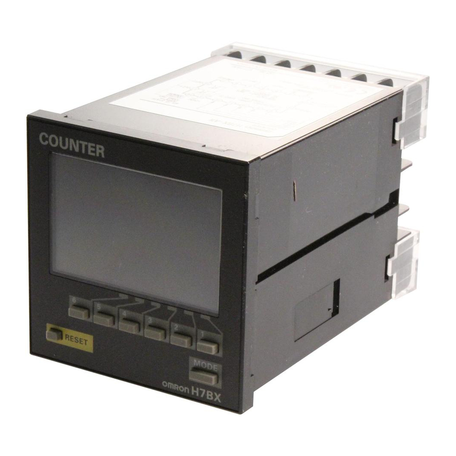
Multifunction Counter
H7BX
DIN 72 72 mm Multifunction Counter with a Bright,
Easy-to-view, Negative Transmissive LCD.
Highly visible display with backlit transmissive LCD.
Selectable display color (red/green) enables checking output status at a
distance.
Easy operation with a key for each digit.
Perform all basic settings with a DIP switch.
Provides a total and preset counter, batch counter, dual counter, and
tachometer (See note.).
Wide range of inputs accepted for NPN/PNP inputs (multi-inputs) and 2-
wire DC sensors.
Complies with UL, CSA, and CE marking.
Degree of protection: IP54 equivalent (front section only).
Note: The functions that can be selected depend on the model.
Ordering Information
■ List of Models
External power supply
Contact and
12 VDC
NPN transistor output
■ Accessories (Order Separately)
Name
Soft Cover
Hard Cover
Terminal Cover (See note.)
Note: Supplied with the H7BX.
Output type
Supply voltage
100 to 240 VAC
24 VAC/12 to 24 VDC
Model
Y92A-72F1
Y92A-72
Y92A-72T
Be sure to read Safety Precautions on page 25.
1-stage
H7BX-A
H7BX-AD1
H7BX
Multifunction Counter
2-stage
H7BX-AW
H7BX-AWD1
1
Advertisement
Table of Contents

Related Manuals for Omron H7BX


Summary of Contents for Omron H7BX
- Page 1 Easy operation with a key for each digit. Perform all basic settings with a DIP switch. Provides a total and preset counter, batch counter, dual counter, and tachometer (See note.). Wide range of inputs accepted for NPN/PNP inputs (multi-inputs) and 2- wire DC sensors.
- Page 2 Counter One-shot output time 0.01 to 99.99 s External reset (minimum reset input signal width: 1 ms or 20 ms selectable), manual reset, and automatic reset (internal Reset input according to C, R, P, and Q mode operation) Pulse measurement...
- Page 3 Square-wave noise by noise simulator (Pulse width: 100 ns/1 s, 1-ns rise) Malfunction: 8 kV Static immunity Destruction: 15 kV Destruction: 10 to 55 Hz, 0.75-mm single amplitude for 4 cycles each in 3 directions (8 Load current (A) Vibration resis- min/cycle)
- Page 4 2. In increment mode or increment/decrement mode, the present value returns to 0; in decrement mode, the present value returns to the set value with 1-stage models, and returns to set value 2 with Note: For details, refer to page 24.
- Page 5 Connections ■ Terminal Arrangement Confirm that the power supply meets specifications before using the H7BX. H7BX-A H7BX-AW 10 11 12 13 14 10 11 12 13 14 External power supply External power supply Unused. Unused. Unused. OUT1 OUT2 protection protection...
- Page 6 ■ Input Connections A no-voltage input (short-circuit or open) or voltage input can be selected for each input. (The key protection input is always a no-voltage input (NPN input)). ● No-voltage Inputs (NPN Inputs) Open Collector Voltage Output Contact Input...
- Page 7 Indicators Operation Keys A Reset Indicator I Mode Key (Orange) Lit when the reset input (1) or reset key is ON. Used to switch mode and setting items. B Key Protection Indicator J Reset Key (Orange) C Control Output Indicator...
- Page 8 10. For details on the setting methods, refer to page 10. Note: The default setting is for a 1-stage preset counter. (For models with a 2-stage setting, the default is a 2-stage preset counter.) Setting for Tachometer Operation (H7BX-AW@ only) ●...
- Page 9 Properly set the DIP switch to match the item being counted (or measured) and use the DIP switch monitor for confirmation. Use the keys on the front panel to perform all settings for input modes, output modes, and output times that cannot be set with the DIP switch. For details on the setting methods, refer to page 10.
- Page 10 When using the H7BX as a Total and Preset Counter, Batch Counter, or Dual Counter, switch the configuration using the procedure on page 23. ■ Setting Advanced Functions Settings that cannot be performed with the DIP switch are performed with the operation keys.
- Page 11 Set the way that control output for the present value is output. 1. Set the decimal point position to 2 decimal places. The possible settings are N, F, C, R, K-1, P, Q, A, K-2, D, L, and 2. Set the prescale value to 0.02 (0.5 25).
- Page 12 ON. Dual Count Value Dual count value Shows the sum of the CP1 present value and CP2 present value when the dual count Dual count set calculating mode is ADD and shows the value obtained by subtracting the CP2 present value value from the CP1 present value when the dual count calculating mode is SUB.
- Page 13 (See note 2.) UP/DOWN C: Quadrature Input Mode Note 1. If the configuration is set to dual counter, CP1 and CP2 inputs will operate in the same way as the count input (CP1) of UP (increment) mode.
- Page 14 One-shot output from OUT1 (The one-shot output time Operation for 1-stage models is the same as that for OUT2. can be set in the range When using a 2-stage model as a 1-stage counter, total and preset counter, 0.01 to 99.99s.) Self-holding Self-holding One-shot output or dual counter, OUT1 and OUT2 turn ON and OFF simultaneously.
- Page 15 4. If there is power failure while an output is ON, the output will turn ON again when the power supply has recovered. For a one-shot output, the output will turn ON again for the duration of the output time setting once the power supply has recovered.
- Page 16 2. If reset/reset 1 input turns ON while the one-shot output is ON, the one-shot output turns OFF. 3. If there is power failure while the output is ON, the output will turn ON again when the power supply has recovered. For a one-shot output, the output will turn ON again for the duration of the output time setting once the power supply has recovered.
- Page 17 6-digit models. Note 1. Counting is not possible for CP1 while the reset 1 input is ON. CP2 is not affected. The dual count value will be calculated based on a CP1 present value of 0.
- Page 18 Present value and Reset/reset 1 Present value and output reset. Present value and output reset. Only the CP1 present value is reset. output reset. Batch count value and batch output Total reset/reset 2 No effect. Only the total count value is reset.
- Page 19 Properly set the DIP switch to match the item being counted (or measured) and use the DIP switch monitor for confirmation. After setting the DIP switch for basic operations, advanced functions (see note) can be added using the operation keys. For details, refer to page 20.
- Page 20 The characters displayed in reverse video are the initial values. When performing settings with operation keys only, turn ON pin 1 of the DIP switch to OFF (factory setting). If pin 1 of the DIP switch is ON, the setting items indicated by will not be displayed.
- Page 21 Auto-zero Time (avt) ★ Set the output method for control output based on the OUT1/ It is possible to set the H7BX so that if there is no pulse for a OUT2 set value. Upper and lower limit (HI-LO), area (AREA), certain time the display is force-set to 0.
- Page 22 OUT1/OUT2 Set Value Set OUT1 set value and OUT2 set value. The Measurement value measurement value is compared to OUT1 set value and OUT2 set value and output is made according to OUT1 set value the selected output mode. Measurement value OUT2 set value ■...
- Page 23 2. Setting changes made in configuration selection mode are enabled when the mode is changed to run mode. If the configuration is changed, the set value (or set value 1 and set value 2), OUT1 set value or OUT2 set value are initialized.
- Page 24 When the key-protect switch is set to ON, it is possible to prevent setting errors by prohibiting the use of certain operation keys by specifying the key protect level (KP-1 to KP-5). The key protect indicator is lit while the key-protect switch is set to ON. Confirm the ON/ OFF status of the key protect switch after the H7BX is mounted to the panel.
- Page 25 Be sure to wire the terminals correctly. occasionally occur. Never attempt to disassemble, Up to two wires of the same size and type can be inserted into modify, or repair the H7BX or touch any of the a single terminal.
- Page 26 Inrush current generated by turning ON or OFF the power supply may deteriorate contacts in the power supply circuit. Turn ON or OFF using a device with a rated current of 10 A or higher. Input signals may be accepted, not accepted, or unstable for the following time when the power supply is turned ON or OFF.
- Page 27 Warranty and Limitations of Liability WARRANTY OMRON's exclusive warranty is that the products are free from defects in materials and workmanship for a period of one year (or other period if specified) from date of sale by OMRON. OMRON MAKES NO WARRANTY OR REPRESENTATION, EXPRESS OR IMPLIED, REGARDING NON-INFRINGEMENT, MERCHANTABILITY, OR FITNESS FOR PARTICULAR PURPOSE OF THE PRODUCTS.
- Page 28 ALL DIMENSIONS SHOWN ARE IN MILLIMETERS. To convert millimeters into inches, multiply by 0.03937. To convert grams into ounces, multiply by 0.03527. Cat. No. M077-E1-01 In the interest of product improvement, specifications are subject to change without notice. OMRON Corporation Industrial Automation Company Control Devices Division H.Q.