
Related Manuals for Omron DEVICENET SAFETY - 03-2008


Summary of Contents for Omron DEVICENET SAFETY - 03-2008
- Page 1 Cat. No. Z904-E1-04 DeviceNet Safety DST1-series Safety I/O Terminals OPERATION MANUAL...
- Page 2 DST1-series Safety I/O Terminals Operation Manual Revised March 2008...
- Page 4 Indicates prohibited actions. OMRON Product References All OMRON products are capitalized in this manual. The word “Unit” is also capitalized when it refers to an OMRON product, regardless of whether or not it appears in the proper name of the product.
- Page 5 OMRON, 2005 All rights reserved. No part of this publication may be reproduced, stored in a retrieval system, or transmitted, in any form, or by any means, mechanical, electronic, photocopying, recording, or otherwise, without the prior written permission of OMRON.
-
Page 6: Table Of Contents
Additional Precautions According to UL1604 ........ - Page 7 Index..........117 Revision History ........121...
- Page 8 DST1 in this manual). Please read this manual carefully and be sure you understand the information provided before attempting to install or operate the DST1. Be sure to read the precautions provided in the following section. The following manuals provide information on the DeviceNet and DeviceNet Safety.
- Page 10 WHETHER SUCH CLAIM IS BASED ON CONTRACT, WARRANTY, NEGLIGENCE, OR STRICT LIABILITY. In no event shall the responsibility of OMRON for any act exceed the individual price of the product on which liability is asserted. IN NO EVENT SHALL OMRON BE RESPONSIBLE FOR WARRANTY, REPAIR, OR OTHER CLAIMS...
- Page 11 The following are some examples of applications for which particular attention must be given. This is not intended to be an exhaustive list of all possible uses of the products, nor is it intended to imply that the uses listed may be suitable for the products: •...
- Page 12 PERFORMANCE DATA Performance data given in this manual is provided as a guide for the user in determining suitability and does not constitute a warranty. It may represent the result of OMRON's test conditions, and the users must correlate it to actual application requirements.
- Page 14 Regulation and Standards ........
-
Page 15: Intended Audience
!WARNING It is extremely important that a PLC and all PLC Units be used for the speci- fied purpose and under the specified conditions, especially in applications that can directly or indirectly affect human life. You must consult with your OMRON representative before applying a PLC System to the above-mentioned appli- cations. - Page 16 • Complying with Laws and Regulations This safety device conforms to the relevant regulations and standards, but make sure that it is used in compliance with local regulations and stan- dards for the equipment or facilities in which it is applied.
-
Page 17: Safety Precautions
Serious injury may possibly occur due to loss of required safety functions. Ground the 0V line of the power supply for external output devices so that the devices do Not turn ON when the safety output line is grounded. -
Page 18: Operating Environment Precautions
For Model DST1-MRD08SL-1, insert a fuse rated at 3.15 A or less for each output terminal to protect safety output contacts from welding. Confirm the fuse selec- tion with the fuse manufacturer to ensure the dependability of the characteris- tics of the connected load. - Page 19 • Mount the DST1 to DIN rails with attachments (TYPE PFP-M, not incor- porated to this product), not to drop out of rails by vibration etc. • Spacing should be available around the DST1 at least 50 mm from its top and bottom surfaces for ventilation and wiring.
-
Page 20: Additional Precautions According To Ul1604
Periodical Inspection and Maintenance • Disconnect the DST1 from power supply when replacing. Devices con- nected to the DST1 may operate unexpectedly. • Do not dismantle, repair, or modify the DST1. It may lead to loss of its safety functions. ■... -
Page 21: Glossary
Data with high reliability. error latch time The time period to hold an error state (control data, status data, and LED indi- cations). open type The open method for Safety Connection. One of three types is selected in the settings of a connection to the Safety Master. -
Page 22: Overview
Logic Terminals ........Description of Safety Functions ........ -
Page 23: Overview
Safety Network Control- ler (NE1A-SCPU01). Also, the status of the safety I/O data can be monitored in a standard PLC in an existing DeviceNet network using standard I/O communications or explicit message communications. -
Page 24: Dst1-Series Safety I/O Terminals Features
• Faults in external wiring can be detected. • Input delays (ON delays and OFF delays) can be set. • Pairs of related local inputs can be set to Dual Channel Mode in order to be compliant with the Category 4 standards. - Page 25 Section 1-1 System Startup and Error Recovery Support • Error information can be checked by using the error log function or the indicators on the front of the DST1-series Safety I/O Terminals. • The DST1-series Safety I/O Terminal’s safety I/O data and internal status information can be monitored from a Standard PLC by allocating the infor- mation in the standard Master.
-
Page 26: Standard Models
(See note.) Note (1) Each test output can be set to function as a test output or a standard out- put. Test outputs are used in combination with a safety input. Broken wires in an external indicator can be detected for terminal T3 only. -
Page 27: Functions
Specifica- pulses. tions Input delays (ON or The input time constant can be set from 0 to 126 ms in units of 6 ms. This OFF) function can be used to reduce the effects of chattering and external noise. Dual channel evalua-... -
Page 28: Input Terminals And I/O Terminals
DST1-series Terminal. DeviceNet Safety Sys- Unit conduction time moni- The total ON time (unit: 0.1 h) of the internal circuit power can be calcu- tem Configu- lated and recorded in the DST1-series Terminal. ration Manual... -
Page 29: Logic Terminals
DST1-series Terminal. DeviceNet Safety Sys- Unit conduction time moni- The total ON time (unit: 0.1 h) of the internal circuit power can be calcu- tem Configu- lated and recorded in the DST1-series Terminal. ration Manual... -
Page 30: Description Of Safety Functions
Self-diagnosis is performed when the power is turned ON and periodically during operation. If an error occurs, it will be treated as a fatal error (the MS indicator will light in red), and the safety outputs and output data to the net- work will turn OFF. -
Page 31: Safety Inputs
A test output is used in combination with a safety input. Specify the corre- sponding test output terminal to use as the test source. The test output termi- nal is used as a power supply to connect an external input device to the safety input terminal. - Page 32 65,530 ms, in increments of 10 ms), the safety input data and the individual safety input status will turn OFF for both inputs. IMPORTANT The dual channel function is used with 2 consecutive inputs that start from even input numbers: inputs 0 and 1, inputs 2 and 3, inputs 4 and 5, etc.
- Page 33 Description of Safety Functions Section 1-4 The following table shows the relation between terminal input and remote I/O data. Dual channel mode Input terminals Remote I/O data Meaning of data Safety input Safety input Dual Channel Equiv- alent Dual Channel Com-...
- Page 34 The status is treated as normal when both channels are ON or OFF. If one channel is ON and the other channel is OFF, it will be treated as an error, and the safety input data and the individual safety input status will turn OFF for both inputs.
- Page 35 • The cause of the error must be removed. • The error latch time must have passed. • The input signal must return to an inactive state and there must be no error condition detected. (e.g., by pressing the emergency stop switch or opening a door)
-
Page 36: Safety Outputs
Safety Outputs Safety Outputs with Test Pulses (Output Circuit Diagnosis) When the output is ON, the test pulse is turned OFF for 470 µ s in a cycle of 648 ms. Using this function, short-circuits between output signal lines and the power supply (positive side) and short-circuits between output signal lines can be detected. -
Page 37: I/O Status Data
Section 1-4 Description of Safety Functions The status is treated as normal when both channels are normal. If an error is detected for one channel, the safety output data and the individual safety out- put status will turn OFF for both channels. -
Page 38: Logic Functions
Overview Safety logic control can be easily performed by setting a combination of I/O data from local I/O terminals and remote I/O data from a Standard Master or Safety Master with the logic operations supported by the DST1-XD0808SL-1. In addition, the safety status can be monitored from standard controls by using the safety output terminals as additional outputs and outputting data such as error information. -
Page 39: Parameters That Can Be Set
Input 0 to Input 5 Safety input terminals IN0 to IN5 The following data is used for remote I/O data. For details on remote I/O allo- cations, refer to 3-2-4 I/O Assembly Data. Bit 7 Bit 6... - Page 40 Data received from Safety Master or Standard Master through the tion signal network IN0 to IN5 Safety input logic operation result The following data is used for remote I/O data. For details on remote I/O allo- cations, refer to 3-2-4 I/O Assembly Data. Bit 7 Bit 6 Bit 5...
- Page 41 Note (1) An additional output can be used only when the output terminals are set as a single channel. (2) An ON delay or OFF delay can be set for safety output terminals even when an additional output is set.
-
Page 42: General Procedure
Installation........... . Connecting I/O Power and I/O Cable ....... -
Page 43: General Procedure
Safety I/O Terminals. Refer to Section 3. The baud rate of the entire system is determined by the baud rate of the Mas- ter Unit. The baud rate does not need to be set for each DST1-series Safety I/O Terminals. -
Page 44: Installation
• Use DIN Track (35 mm wide) to mount the DST1 in the control panel. • Always use an End Plate on each end of the DST1 to secure it. • Allow a minimum of 50 mm above and below the DST1 for ventila-... -
Page 45: Connecting I/O Power And I/O Cable
Confirm before application.) Note (1) If the terminal block is wired with ferrules, firmly insert them all the way in. (2) When using 2-wire ferrules, the power lines must be of the same diame- ter. - Page 46 • Separate I/O signal cables from high-voltage lines and power lines. • I/O signal cables must be no longer than 30 m. • Do not apply power to safety output terminals or test output terminals. Doing so may cause burning or other damage to the product.
-
Page 47: Connecting The Communications Connector
Connecting the Communications Connector Colored stickers are provided on the communications connector that match the colors of the lines to be inserted. Check that the colors of the lines and stickers match when wiring the connectors. The colors are as follows:... -
Page 48: Node Address
A value between 00 and 63 can be set. Ones digit of node address Tens digit of node address If a node address between 64 and 99 is set, the node address can be set from the Network Configurator. IMPORTANT •... - Page 49 Section 2-6 Configuration...
-
Page 50: Configuration
General Parameters ........ -
Page 51: Editing Device Parameters
The DST1-series Safety I/O Terminals have five parameter groups: General Parameters, Safety Input Parameters, Test Output Parameters, Safety Output Parameters, and Operating Time Parameters. The settings in each parameter group are listed in the following tables. All parameters are set using the Network Configurator. Note... -
Page 52: General Parameters
Safety I/O communications are not possible in this mode. IMPORTANT If the power is turned OFF in Idle Mode, the next operation will not start in RUN Mode even if Auto Execution is set as the execution mode and the con- figuration is locked. -
Page 53: Safety Input Parameters
Note When the Safety Input Channel Mode is set to Test Pulse from Test Out, spec- ify the test output to use for the test source and set the Test Output Mode of the test output to Pulse Test Output. -
Page 54: Test Output Parameters
Power Supply Output Specifies connecting to the power supply terminal of a safety sensor. The voltage supplied from the test output to the I/O power supply (V, G) is out- put. Muting Lamp Output Specifies a muting lamp output. -
Page 55: Safety Output Parameters
--- I/O Comment 32 characters max. Sets an I/O comment for the safety output. The I/O None comment set here is used as the I/O tag in the NE1A-series Logic Editor. --- Maintenance Counter Time Sets the operating mode for the maintenance... -
Page 56: Safety Input Logic Parameter Groups (Safety Input Logic)
The I/O comment set here is used as the I/O tag by the NE1A-series Logic Editor. Note Safety input parameter groups can be set only for DST1-XD0808SL-1 safety inputs IN0 to IN5. For details on DST1-XD0808SL-1 logic functions, refer to 1- 5 Logic Functions. -
Page 57: Safety Output Logic Parameter Groups (Safety Output Logic)
0 ms 100 ms) Note (1) Turns OFF (0) when one of the errors shown in 7-3 Error History occurs. (2) Safety output parameter groups can be set only for DST1-XD0808SL-1 safety outputs OUT0 to OUT7. For details on DST1-XD0808SL-1 logic... -
Page 58: Remote I/O Allocations
3-2-1 I/O Allocations The DST1-series Safety I/O Terminals internally store I/O data. Connection paths can be set using the Network Configurator to allocate I/O data for the Master Unit. Be sure to set the required connection paths. 3-2-2 I/O Data The DST1-series Safety I/O Terminals store the following data. -
Page 59: I/O Data Supported By Each Model
Bit 7 Connected Component Maintenance Flag 0: Within range (all I/O points are lower than set monitor value) 1: Over range (one or more I/O point is same as or higher than set monitor value) Output data Safety Output Data Controls the safety output terminal. - Page 60 Section 3-2 Remote I/O Allocations From among the I/O data, safety connections for up to four items, including one output, can be allocated for the Master Unit and standard connections for up to two items can be allocated for the Master Unit.
- Page 61 Section 3-2 Remote I/O Allocations DST1-MD16SL-1 The default values for the I/O assembly data are as follows: Safety connections: Default (Assembly instance number) Safety input assembly 1 (Instance No. 204) Safety output assembly 1 (Instance No. 234) Standard connection: The default values for each type of connection are given below.
- Page 62 Remote I/O Allocations Section 3-2 DST1-MRD08SL-1 The default values for the I/O assembly data are as follows: Safety connections: Default (Assembly instance number) Safety input assembly 1 (Instance No. 203) Safety output assembly 1 (Instance No. 233) Standard connection: The default values for each type of connection are given below.
- Page 63 Remote I/O Allocations Section 3-2 DST1-XD0808SL-1 The default values for the I/O assembly data are as follows: Safety connections: Default (Assembly instance number) Safety input assembly 1 (Instance No. 204) Safety output assembly 1 (Instance No. 352) Standard connection: The default values for each type of connection are given below.
-
Page 64: I/O Assembly Data
Safety Safety Input 7 Input 6 Input 5 Input 4 Input 3 Input 2 Input 1 Input 0 Applicable Terminals: DST1-MD16SL-1 and DST1-XD0808SL-1 Instance Byte Bit 7 Bit 6 Bit 5 Bit 4 Bit 3 Bit 2 Bit 1 Bit 0... - Page 65 Bit 7 Bit 6 Bit 5 Bit 4 Bit 3 Bit 2 Bit 1 Bit 0 (hex) General Status Applicable Terminal: DST1-ID12SL-1, DST1-MD16SL-1, DST1-MRD08SL-1 Instance Byte Bit 7 Bit 6 Bit 5 Bit 4 Bit 3 Bit 2 Bit 1...
- Page 66 Section 3-2 Remote I/O Allocations Instance Byte Bit 7 Bit 6 Bit 5 Bit 4 Bit 3 Bit 2 Bit 1 Bit 0 (hex) Safety Safety Safety Safety Safety Safety Safety Safety Input 7 Input 6 Input 5 Input 4...
- Page 67 Section 3-2 Remote I/O Allocations Instance Byte Bit 7 Bit 6 Bit 5 Bit 4 Bit 3 Bit 2 Bit 1 Bit 0 (hex) Safety Safety Safety Safety Safety Safety Safety Safety Input 7 Input 6 Input 5 Input 4...
- Page 68 Remote I/O Allocations Section 3-2 Instance Byte Bit 7 Bit 6 Bit 5 Bit 4 Bit 3 Bit 2 Bit 1 Bit 0 (hex) Safety Safety Safety Safety Safety Safety Safety Safety Input 3 Input 2 Input 1 Input 0...
- Page 69 Section 3-2 Remote I/O Allocations Instance Byte Bit 7 Bit 6 Bit 5 Bit 4 Bit 3 Bit 2 Bit 1 Bit 0 (hex) Safety Safety Safety Safety Safety Safety Safety Safety Input 7 Input 6 Input 5 Input 4...
- Page 70 Bit 0 (hex) Reserved Standard Standard Standard Standard Output 3 Output 2 Output 1 Output 0 Applicable Terminal: DST1-ID12SL-1, DST1-MD16SL-1, DST1-MRD08SL-1 Instance Byte Bit 7 Bit 6 Bit 5 Bit 4 Bit 3 Bit 2 Bit 1 Bit 0 (hex)
-
Page 71: Changing Default Standard I/O Assembly Data (Dst1-Xd0808Sl-1 Only)
I/O assembly data (Default Connection Path). This func- tion is enabled for communications with a Standard Master which cannot change I/O assembly data. This kind of Standard Master can perform stan- dard I/O communications with a Standard Slave using default I/O assembly data only. - Page 72 Cyclic) and I/O data size agree with the settings that were made in step 1 above. Note “Null” means that I/O assembly data is not used, i.e., that the data size is 0 bytes. The output connection size for a Bit-Strobe connection is always 0 bytes.
- Page 73 Section 3-2 Remote I/O Allocations...
-
Page 74: Specifications
MS/NS Indicators ........ -
Page 75: Specifications
Combination of multi-drop and T-branch connections (for trunk or branch lines) Baud rate 125 kbps, 250 kbps, or 500 kbps Communications media Special 5-wire cable (2 signal lines, 2 power lines, 1 shield line) Communications distances Baud rate Network length... - Page 76 Standard I/O Communications Number of connections Connection type Poll/Bit-strobe/COS/Cyclic Poll/Bit-strobe/COS/Cyclic Note Communications are enabled with 15 Safety Masters for each multi-cast con- nection, but if four connections are used, it is not possible to communicate with more than 30 Safety Masters total.
-
Page 77: Indicators
The NS (Network Status) indicator displays the status of the entire network. The MS and NS indicators can be green or red and they can be ON, flashing, or OFF. The meanings indicated by the combination of their colors and status are as given in the following table. -
Page 78: In Pwr/Out Pwr Indicators
Section 4-2 Indicators 4-2-3 IN PWR/OUT PWR Indicators The IN PWR and OUT PWR indicators indicate the status of the I/O power supplied to the DST1-series Safety I/O Terminals. LED Indicators Color Status Meaning IN PWR Green Normal status of input power Input power is not supplied. - Page 79 Section 4-2 Indicators...
-
Page 80: Dst1 Series Specifications
Nomenclature ........ -
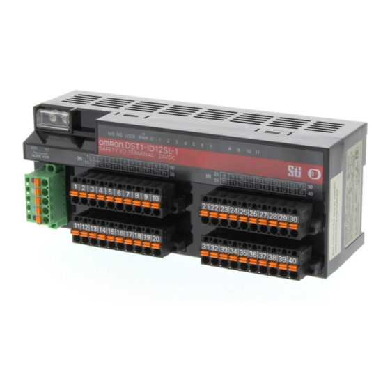
Page 81: Dst1-Id12Sl-1
Residual voltage 1.2 V max. between each output terminal and V Leakage current 0.1 mA max. 5-1-3 Nomenclature The following figure shows the names of the parts of the DST1-ID12SL-1. Node address switches LED indicators DeviceNet communications connector Terminal blocks •... -
Page 82: Internal Circuits And Terminal Arrangement
Safety input circuits Test output circuits supply (current sinking) (current sourcing) circuit The following table gives the terminal arrangement of the terminal blocks on the DST1-ID12SL-1. Terminals Names Functions 1, 2 Power terminals for the input devices and test outputs. (24 VDC) -
Page 83: Dimensions
Section 5-1 DST1-ID12SL-1 I/O Power Supply Circuit Test Output Circuit T0...T3 Internal Safety Input Circuit Circuit IN0...IN11 5-1-5 Dimensions The following figures show the dimensions of the DST1-ID12SL-1 (unit: mm). 71.4... -
Page 84: Dst1-Md16Sl-1
Leakage current 0.1 mA max. IMPORTANT In case that a safety output is configured as Safety pulsed test, while this out- put is in an ON state, the signal sequence shown below is output continuously to enable diagnosis. Confirm the response times of the devices connected to the safety outputs so that the devices do not malfunction due to the OFF pulse. -
Page 85: Nomenclature
Section 5-2 DST1-MD16SL-1 5-2-4 Nomenclature The following figure gives the names of the parts of the DST1-MD16SL-1 Node address switches LED indicators DeviceNet communications connector Terminal blocks • Refer to 4-2 Indicators for information on the LED indicators. • Refer to 2-4 Connecting the Communications Connector for information on the DeviceNet communications connector. - Page 86 ...OUT7 IMPORTANT Power supply terminal V1 for the outputs is internally monitored. Supply the voltage in the specified range (20.4 to 26.4 VDC). If the voltage is supplied outside this range, voltage will not be supplied to the output circuits.
-
Page 87: Dimensions
Section 5-2 DST1-MD16SL-1 5-2-6 Dimensions The following figures show the dimensions of the DST1-MD16SL-1 (unit: mm). 71.4... -
Page 88: Dst1-Mrd08Sl-1
Section 5-3 DST1-MRD08SL-1 DST1-MRD08SL-1 5-3-1 Safety Input Specifications The following table gives the safety input specifications for the DST1- MRD08SL-1. Item Specifications Input type Sinking input (PNP) ON voltage 11 VDC min. between each input termi- nal and G0 OFF voltage 5 VDC max. -
Page 89: Nomenclature
Section 5-3 DST1-MRD08SL-1 5-3-4 Nomenclature The following figure shows the names of the parts of the DST1-MRD08SL-1. Node address switches LED indicators Safety relays DeviceNet communications connector Terminal blocks • Refer to 4-2 Indicators for information on the LED indicators. - Page 90 OUT0 to OUT3 Terminals for safety outputs 33 to 40 C0 to C3 Outputs of terminals 23/33 (OUT0) and 24/34 (OUT0e) are the same. OUT0e to OUT3e Output of terminals 25/35 (OUT1) and 26/36 (OUT1e) are the same. C0e to C3e Output of terminals 27/37 (OUT2) and 28/38 (OUT2e) are the same.
- Page 91 F1, F2, and F3. For Model DST1-MRD08SL-1, Insert a fuse rated at 3.15 A or less for each out- put terminal to protect safety output contacts from welding.
-
Page 92: Dimensions
DST1-MRD08SL-1 Section 5-3 5-3-6 Dimensions The following figures show the dimensions of the DST1-MRD08SL-1 (unit: mm). 83.2... -
Page 93: Dst1-Xd0808Sl-1
Leakage current 0.1 mA max. When the safety output channel mode for a safety output terminal is set to Safety Pulse Test, the following pulse signal is output when the safety output turns ON. Confirm the input response times for control devices connected the safety outputs so that the devices do not malfunction due to the OFF pulse. -
Page 94: Internal Circuits And Terminal Arrangement
I/O connectors • Refer to 4-2 Indicators for details on the LED indicators. • Refer to 2-4 Connecting the Communications Connector for details on the DeviceNet communications connector. • Refer to 5-4-5 Internal Circuits and Terminal Arrangement for details on the terminal arrangement. - Page 95 Power supply terminal V1 for the output devices is internally monitored. Sup- ply the voltage in the specified range (20.4 to 26.4 VDC). If the voltage is sup- plied outside this range, voltage will not be supplied to the output circuits.
-
Page 96: Dimensions
Section 5-4 DST1-XD0808SL-1 5-4-6 Dimensions The following figures show the dimensions of the DST1-XD0808SL-1 (unit: mm). 71.4... - Page 97 Section 5-4 DST1-XD0808SL-1...
-
Page 98: Response Performance
Input Reaction Time ........ -
Page 99: Reaction Time
6-1-2 Input Reaction Time The input reaction time is the time from when an input terminal signal is changed until an output is sent to the network. The input reaction time is determined as follows: Input reaction time = 16.2 ms + Input ON/OFF delay time... -
Page 100: Troubleshooting And Maintenance
Safety Output Errors ........ -
Page 101: Indicators And Error Processing
Are cables broken or loose? Are Terminating Resistors connected to both ends of the trunk line only? Is noise interference excessive? Node address duplication Reset the DST1 so that it has a unique node address, and then restart the DST1. − − −... -
Page 102: Troubleshooting
Or error code Information (1 to 12) speci- Read fied by the instance ID turn- ing OFF. (See note.) Note The instance numbers for safety inputs 0 to 11 are 1 to 12 (01 to 0C hex), respectively. -
Page 103: Test Output Errors
Or error code Information (1 to 4) specified Read by the instance ID turning OFF. (See note.) Note The instance numbers for test outputs 0 to 3 are 1 to 4 (01 to 04 hex), respec- tively. -
Page 104: Safety Output Errors
Or error code Information (1 to 8) specified Read by the instance ID turning OFF. (See note.) Note The instance numbers for safety outputs 0 to 7 are 1 to 8 (01 to 08 hex), respectively. -
Page 105: Error History
Message Countermeasure DST1 Series System Failures System Failure Check to see if the positive side of the power supply is in contact with the signal line. Replace the DST1 if the system failure still occurs after turning ON the power. - Page 106 • Make sure the output signal wire does not have an earth fault. Short Circuit Detected at Safety Output • Make sure the output signal wire is not contacting the positive side of Over Current Detected at Safety Output the power supply.
-
Page 107: Maintenance
• Wipe the DST1-series Safety I/O Terminals with a dry, soft cloth for regu- lar cleaning. • When dust or dirt cannot be removed with a dry cloth, dampen the cloth with a neutral cleanser (2%), wring out the cloth, and wipe the DST1- series Safety I/O Terminals. -
Page 108: Replacing The Dst1
Replacing the DST1 The network consists of the DeviceNet Unit (master) and DST1 Terminals. The entire network is affected when a DST1 is faulty, so a faulty DST1 must be repaired or replaced quickly. We recommend having spare DST1 Termi- nals available to restore network operation as quickly as possible. - Page 109 Section 7-4 Maintenance...
-
Page 110: Wiring Examples
8-2-4 Muting Lamp Output ........ -
Page 111: Wiring And Configuration
Section 8-1 Wiring and Configuration Wiring and Configuration The following table shows input device connection methods and configuration. Connected Schematic diagram Configuration device Reset switch Connect the switch between IN0 and T0. Safety Input used as “Single Channel input” with- out test output. -
Page 112: Examples Of Wiring For Each Application
Examples of Wiring for Each Application Examples of Wiring for Each Application 8-2-1 Emergency Stop Switch Dual Channel Inputs with Manual Reset An example of the wiring and configuration when using the DST1-ID12SL-1 is shown below. Wiring E1: 24-V DC Power Supply (S8@@) - Page 113 Section 8-2 Examples of Wiring for Each Application 8-2-2 Two-Hand Input An example of the wiring and configuration when using the DST1-ID12SL-1 is shown below. Wiring E1: 24-V DC Power Supply (S8@@) S11,S12: Two-hand control switches Configuration Parameter Parameter Name...
- Page 114 Section 8-2 Examples of Wiring for Each Application 8-2-3 User Mode Switch Input An example of the wiring and configuration when using the DST1-ID12SL-1 is shown below. Wiring E1: 24-V DC Power Supply (S8@@) S1: User mode switch Configuration Parameter...
- Page 115 Section 8-2 Examples of Wiring for Each Application 8-2-4 Muting Lamp Output An example of the wiring and configuration when using the DST1-ID12SL-1 is shown below. Wiring E1: 24-V DC Power Supply (S8@@) L1: External muting lamp Configuration Parameter Parameter name...
- Page 116 Section 8-2 Examples of Wiring for Each Application 8-2-5 Limit Switch Dual Channel Inputs and a Manual Reset An example of the wiring and configuration when using the DST1-ID12SL-1 is shown below. Wiring E1: 24-V DC Power Supply (S8@@) S1: Safety Limit Switch (D4D or D4B)
- Page 117 Section 8-2 Examples of Wiring for Each Application 8-2-6 Safety Light Curtain Input An example of the wiring and configuration when using the DST1-ID12SL-1 is shown below. Wiring E1: 24-V DC Power Supply (S8@@) F3SN-A: Safety Light Curtain F3SN-A Receiver...
- Page 118 Section 8-2 Examples of Wiring for Each Application 8-2-7 Semiconductor Outputs for Dual Channel Mode An example of the wiring and configuration when using the DST1-MD16SL-1 is shown below. Wiring E1: 24-V DC Power Supply (S8@@) L1, L2: Loads Configuration...
- Page 119 Section 8-2 Examples of Wiring for Each Application 8-2-8 Relay Outputs with Dual Channel Mode and EDM Input An example of the wiring and configuration when using the DST1-MRD08SL- 1 is shown below. Wiring E1, E2: 24-V DC Power Supply (S8@@)
-
Page 120: Logic Terminal Wiring Examples
Section 8-3 Logic Terminal Wiring Examples Logic Terminal Wiring Examples 8-3-1 Stopping Outputs by Using an Emergency Stop Switch or a Signal from a Safety Master An example of the wiring and configuration when using the DST1-XD0808SL- 1 is shown below. - Page 121 Pulse Test Output Pulse Test Output Port Safety Output Parameter Channel Mode Off On On Off Dual Channel Mode Delay Delay OUT 0 Safety Pulse Test 0 ms 0 ms Dual Channel OUT 1 Safety Pulse Test 0 ms 0 ms...
- Page 122 Section 8-3 Logic Terminal Wiring Examples...
- Page 123 Section 8-3 Logic Terminal Wiring Examples...
-
Page 124: Appendix
The parameters used for specifying the command, processing object, and processing content. Note The number of bytes designated for the class ID, instance ID, and attribute ID depend on the Master Unit. When sent from an OMRON DeviceNet Master, the class ID and instance ID are 2 bytes (4 digits) each, and the attribute ID is 1 byte (2 digits). - Page 125 Appendix 1 DeviceNet Explicit Messages Service Code For normal completions, the service code specified in the command with the leftmost bit turned ON is stored as shown in the following table. Function Command service code Response service code Read data...
- Page 126 General Sta- Read Reads the speci- 0E hex 95 hex 01 hex 65 hex 1 byte tus Read fied slave’s status flags (8 bits) Setting and Monitoring the Unit Conduction Time Explicit Read/ Function Command Response message write Service Class Instance...
- Page 127 Appendix 1 DeviceNet Explicit Messages Setting and Monitoring a Safety Input Explicit Read/ Function Command Response message write Service Class Instance Attribute Data size Code Terminal Read Reads the monitor 0E hex 3D hex 01 to 0C 65 hex 1 byte...
- Page 128 Class Instance Attribute Data size Code Input Monitor Read Reads the set 0E hex 3D hex 01 to 0C 67 hex 1 byte Status for value for the total 00 hex: Within Total ON ON time (unit: s) or range...
- Page 129 Appendix 1 DeviceNet Explicit Messages Setting and Monitoring the Safety Output Point Explicit Read/ Function Command Response message write Service Class Instance Attribute Data size Code Terminal Read Reads the monitor 0E hex 3B hex 01 to 08 65 hex...
- Page 130 Class Instance Attribute Data size Code Output Moni- Read Reads the set 0E hex 3B hex 01 to 08 67 hex 1 byte tor Status for value for the total 00 hex: Within Total ON ON time or number range...
- Page 131 Appendix 1 DeviceNet Explicit Messages Setting and Monitoring the Test Output Point Explicit Read Function Command Response message /write Service Class Instance Attribute Data size Code Terminal Main- Read Reads the monitor 0E hex 09 hex 01 to 04 65 hex...
- Page 132 /write Service Class Instance Attribute Data size Code Output Monitor Read Reads the set value 0E hex 09 hex 01 to 04 67 hex 1 byte Status for Total for the total ON 00 hex: Within ON Time or...
- Page 133 DeviceNet Explicit Messages Appendix 1 Setting and Monitoring Operation Time Explicit Read Function Command Response message /write Data size Service Class Instance Attribute Data size Code Set Value for Read Reads the monitor 0E hex 97 hex 01 to 08...
- Page 134 (1 to 4) speci- Hold fied by the instance ID. The setting can be read for a specified number of points. Note The default setting is for all outputs to be cleared (0). Writing Maintenance Information Explicit Read Function Command...
- Page 135 DeviceNet Explicit Messages Appendix 1 A-1-3 Using Explicit Messages The following example shows how to use explicit messages with the DST1-series Safety I/O Terminals using a CS1W-DRM21 DeviceNet Unit (Master). Example: Reading the Monitor Status for the Operation Time Monitor Example Conditions...
- Page 136 003D hex Class ID: 003D hex D01003 0001 hex Instance ID: 0001 hex D01004 6E** hex Attribute ID: 6E@@ hex (Set any value for the blank boxes.) Contents of C Address Contents Meaning D00000 0009 hex Number of bytes of command data...
- Page 137 Appendix 2: Calculated Values of PFD and PFH Calculated values of PFD and PFH of the DST1-series Safety I/O Terminals are given in the following tables. These values must be calculated for the overall devices within the system to comply with the SIL level required for application.
-
Page 138: Index
Index safety output specifications terminal arrangement applications test output specifications precautions DST1-XD0808SL-1 dimensions internal circuits nomenclature safety input specifications cleaning safety output specifications communications connector terminal arrangement configuration test output specifications configuration lock indicator dual channel mode configuration status complementary... - Page 139 Index I/O assembly data parameters general I/O cables operation time I/O data safety input I/O indicators safety output I/O power supply indicators test output I/O status data password protection IN PWR indicator indicators calculated values error processing inspection calculated values...
- Page 140 DeviceNet communications safety inputs test outputs weight standard models standards terminal arrangement DST1-ID12SL-1 DST1-MD16SL-1 DST1-MRD08SL-1 DST1-XD0808SL-1 test output parameters test output specifications DST1-ID12SL-1 DST1-MD16SL-1 DST1-MRD08SL-1 DST1-XD0808SL-1 test outputs errors troubleshooting two-hand input user mode switch input weight wiring examples input devices...
- Page 141 Index...
-
Page 142: Revision History
Revision History The manual revision is indicated at the end of the Cat. No. printed at the lower left of back cover of the manual. Cat. No. Z904-E1-04 Revision code The following table outlines the changes made to the manual during each revision. Page numbers refer to the previous version.