Omron CPM1A Datasheet
Smallest plc in the sysmac c series
Hide thumbs
Also See for CPM1A:
- Operation manual (201 pages) ,
- Manual (25 pages) ,
- Brochure & specs (6 pages)
Table of Contents
Advertisement
OMRON Corporation
Regional Headquarters
FA Systems Division H.Q.
OMRON EUROPE B.V.
66 Matsumoto
Wegalaan 67-69, NL-2132 JD Hoofddorp
Mishima-city, Shizuoka 411-8511
The Netherlands
Japan
Tel:(31)2356-81-300/Fax:(31)2356-81-388
Tel:(81)55-977-9181
OMRON ELECTRONICS LLC
Fax:(81)55-977-9045
1 East Commerce Drive, Schaumburg, IL 60173
U.S.A.
Tel:(1)847-843-7900/Fax: (1)847-843-8568
OMRON ASIA PACIFIC PTE. LTD.
83 Clemenceau Avenue,
#11-01, UE Square,
Singapore 239920
Tel:(65)6835-3011/Fax : (65)6835-2711
Authorized Distributor:
Note: Specifications subject to change without notice.
Cat. No. P039-E1-11
Printed in Japan
0404-1M
SYSMAC C1000H/C2000H
Smallest PLC in the SYSMAC C Series
Programmable Controllers
SYSMAC C20H
/C28H
/C40H
+
- - -
SYSMAC C20P/C28P/C40P
SYSMAC C60H
SYSMAC C200H
/C200HS
V1-type CPU Units
V1-type CPU Units
Now Available
Now Available
COM
01
03
05
NC
00
02
04
0CH
00
01
02
03
04
05
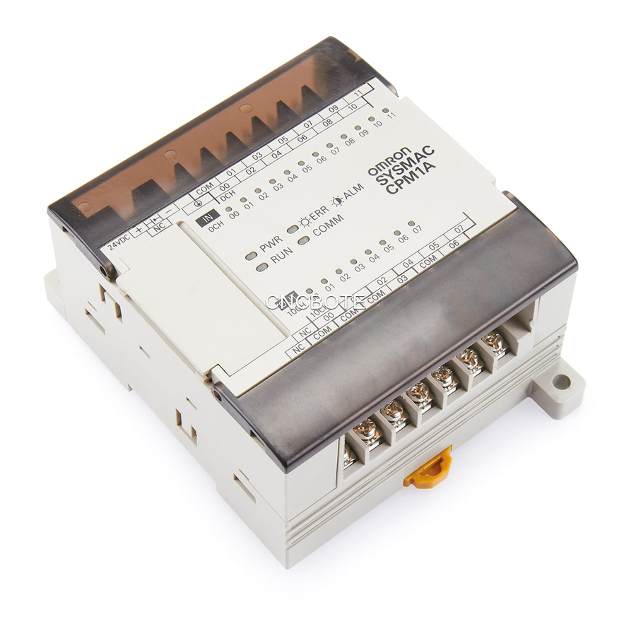
SYSMAC CPM1A
PWR
ERR
ALM
RUN
COMM
10CH 00
01
02
03
NC
00
01
02
COM
COM
COM
03
NC
SYSMAC CPM1A
Advertisement
Table of Contents

Related Manuals for Omron CPM1A


Summary of Contents for Omron CPM1A
- Page 1 SYSMAC C1000H/C2000H SYSMAC C60H Smallest PLC in the SYSMAC C Series Programmable Controllers SYSMAC C200H /C200HS SYSMAC C20H /C28H /C40H V1-type CPU Units V1-type CPU Units Now Available Now Available - - - SYSMAC CPM1A COMM 10CH 00 SYSMAC CPM1A...
-
Page 2: Table Of Contents
Programmable Controllers The Smallest PLC in the SYSMAC Fam ily Shows Just How Far Downsizing Can Go The SYSMAC C Series began developing a wide range of Programmable Controllers to meet factory automation needs in 1973. And now the CPM1A joins the C Series... - Page 3 Select Units to Control from 10 to 100 I/O Points in the Minimum Body Size CPUs are available with from 10 to 40 I/O points and, in combination with Expansion I/O Units, can be used to control a total of from 10 to 100 points.
-
Page 4: System Configuration
System Configuration CPM1A Line-up • DC input • RY output / TR output CPU with AC Power Supply • DC input • RY output / TR output CPU with DC Power Supply 10 I/O points 20 I/O points 30 I/O points... -
Page 5: Cpm1A System Configuration
CompoBus/S I/O LInk Unit DeviceNet I/O Link Unit CPM1A-TS001/101 In addition to the CPU Unit, Expansion Units from the groups indicated in the above table can be combined as shown below. Possible Expansion Unit Combinations Expansion Unit 1 Expansion Unit 2 Expansion Unit 3 Note: 1. -
Page 6: Specifications
500 g max. 600 g max. Note: The specifications of the Expansion I/O Unit are the same as for the CPU except that the power is supplied from the CPU and the weight is 300 g. Power Consumption for DC Models The power consumptions for CPM1A CPU Units and Expansion I/O Units are given in the tables below. -
Page 7: Performance Specifications
Together with the external interrupt input (minimum pulse width of 0.2 ms) Input time constant Can be set at 1 ms, 2 ms, 4 ms, 8 ms, 16 ms, 32 ms, 64 ms, or 128 ms. Analog settings 2 points: (0 to 200) -
Page 8: I/O Specifications
IN00000 to IN00002. Note: 1. The actual ON/OFF delay includes an input constant of 1, 2, 4, 8, 16, 32, 64, or 128 ms (default: 8 ms). 2. The delays for IN00000 to IN00002 are as follows when used for the high-speed counter. - Page 9 2. When using the pulse output function of the CPM1A with transistor outputs (sink type and source type): The output current must be within a range from 100 to 200 mA when using the output 01000 or 01001 as a pulse output with the maximum frequency of 2 kHz.
- Page 10 Note 1. The conversion time is the total time for 2 analog inputs and 1 analog output. 2. The voltage output and current output can be used at the same time, but the total output current cannot exceed 21 mA.
-
Page 11: Cpm1A-Drt21 Devicenet I/O Link Unit
CPM1A-DRT21 DeviceNet I/O Link Unit By connecting the DeviceNet I/O Link Unit (CPM1A-DRT21), the CPM2A can function as the slave of a DeviceNet D Master Unit. In this configuration, I/O links for up to 32 inputs and 32 outputs can be created. -
Page 12: Communications Adapter Specifications Cpm1-Cif01/Cif11
38.4 Kbits/s max. Vibration resistance 10 to 57 Hz with an amplitude of 0.075 mm, and 57 to 150 Hz with an acceleration of 9.8 m/s in the X, Y and Z directions for 80 minutes each in accordance (i.e. swept for 8 minutes, 10 times). -
Page 13: Cpm2C-Pa201 Ac Power Supply Unit
CPM2C-PA201 AC Power Supply Unit The CPM2C-PA201 is a compact, streamlined Unit that can be used as the power supply for PCs, such as the CPM1A and CPM2A, and indicators. (When using the CPM2C-PA201, connection must be performed by the user.) -
Page 14: Functions
Functions Input Interrupts There are two input interrupts in the CPM1A 10-point I/O CPU and four in the 20-, 30-, and 40-point I/O CPUs. Input interrupts are available in two modes. Application Example: 10-point I/O CPU 20-, 30-, and 40-point I/O CPU... -
Page 15: Quick-Response Inputs
Quick-response Inputs There are two quick-response inputs for the CPM1A 10-point I/O CPU and four for the 20-, 30-, and 40-point I/O CPU (shared with the interrupt inputs). Since an internal buffer is provided, the quick-response input function can even detect signals modified within one cycle. -
Page 16: Interval Timer Interrupts
Interval Timer Interrupts The CPM1A has one interval timer. The interval timer shuts down the regular program irrelevant of the point in the cycle once the time is up, and immediately executes an interrupt processing program. Interval timers are used in the following two modes. -
Page 17: Pulse Output Function
0 (0 to 200) Multiplication result (0 to 600) DM 0500 Pulse Output Function The CPM1A with transistor output has a function that is capable Program Example of outputting a pulse of up to 2 kHz. 1 scan turns ON. -
Page 18: Communications
CPM1A host link communications consist of interactive procedures whereby the CPM1A returns a response to a command sent from the IBM PC/AT or compatible computer. These communications allow the IBM PC/AT or compatible computer to read and write in the CPM1A’s I/O Areas and Data Memory Areas as well as in areas containing the status of various settings. - Page 19 Limitations of the CPM1A 1:1 Link CPM1A I/O links are limited to 16 words (LR 00 to LR 15). Therefore, use these 16 words (LR 00 to LR 15) on the CQM1 or C200Hj side when forming 1:1 links with a CQM1 or C200Hj.
-
Page 20: Programming Instructions
Instructions marked with (@) in the mne- monics can also be used as differentiated instructions. Here the Note: f: Instruction keys allocated to the Programming Con- input rise time (shift from OFF to ON) is used to execute the sole. instruction in just one cycle. -
Page 21: Step Instructions
Code Function Instruction Mnemonic Code Function STEP DE- STEP Defines the start of a new step BCD TO (@)BIN Converts 4-digit BCD data to FINE and resets the previous step BINARY 4-digit binary data. when used with a control bit. -
Page 22: Data Movement Instructions
SHIFT shift data to the left or right. LOGICAL (@)ORW Logically ORs the correspond- REGISTER ing bits of two words (or Note: f: Instruction keys allocated to the Programming Con- constants). sole. EXCLU- (@)XORW Exclusively ORs the corre- SIVE OR... -
Page 23: Programming Instructions
INTER- (@)INT Performs interrupt control, RUPT such as masking and unmask- Special System Instructions CONTROL ing the interrupt bits for I/O in- terrupts. Instruction Mnemonic Code Function (@)STC Sets Carry Flag 25504 to 1. Peripheral Device Control Instructions... -
Page 24: Peripheral Devices
Peripheral Devices CPM1A CPU IBM PC/AT or compatible CX-Programmer: WS02-CXPC1-E-V4j (for Windows 95, 98, Me, NT 4.0, 2000, or XP) CX-Programmer Ç Ç Ç Ç Ç Ç RS-232C USB-Serial Conversion Cable CS1W-CIF31 Peripheral Device Connecting Cable CQM1-CIF02 Programming Programming Console... - Page 25 The abbreviations used in the “Standards” column in the following tables indicate the following international standards. U: UL, C:CSA, UC: cULus, CU: cUL, N: NK, L: Lloyd, CE: EC Directives See OMRON sales representatives for conditions under which UL, CSA, cULus, cUL, NK, LLOYD, and CE standards were met.
-
Page 26: Standard Models
CPM1A-SRT21 I/O Link Unit max. and 8 output bits (See note.) Note: Only one Expansion Unit can be connected if an NT-AL001 Adapter is connected to the CPU Unit’s RS-232C port. Temperature Sensor Units Unit Output type Model Standards Temperature... - Page 27 Standard Models RS-232C Adapter, RS-422 Adapter, Connecting Cable, Link Adapter Name Function Model Standards Converts peripheral port levels. U, C, N, L, RS-232C Adapter CPM1-CIF01 RS-422 Adapter CPM1-CIF11 Connecting Cable 3.3-m cable used to connect IBM PC/AT CQM1-CIF02 U, C, N, L, or compatible personal computers.
-
Page 28: Expansion Memory Unit
All contents of EEPROM written Ladder program and expansion Read from PC to EEPROM. instructions to PC. DM 6144 to 6655 Not affected. Note: For details on program size, DM area, and the availability of expansion instructions, refer to the relevant PC manual. - Page 29 PROFITS OR COMMERCIAL LOSS IN ANY WAY CONNECTED WITH THE PRODUCTS, WHETHER SUCH CLAIM IS BASED ON CONTRACT, WARRANTY, NEGLIGENCE, OR STRICT LIABILITY. In no event shall the responsibility of OMRON for any act exceed the individual price of the product on which liability is asserted.