Sennheiser EM 3731-II Instruction Manual
Hide thumbs
Also See for EM 3731-II:
- Manual (2 pages) ,
- Instruction manual (50 pages) ,
- Instruction manual (50 pages)
Table of Contents
Advertisement
Quick Links
Advertisement
Table of Contents

Related Manuals for Sennheiser EM 3731-II


Summary of Contents for Sennheiser EM 3731-II
- Page 1 EM 3731-II EM 3732-II EM 3732-II Command Instruction manual...
-
Page 2: Table Of Contents
Connecting the amplifier/mixing console ........... 17 Connecting devices with AES3 digital input ........17 Connecting an external word clock generator ........17 Connecting the receivers to a PC via Ethernet ........18 Using the receiver ..................19 Switching the receiver on/off ..............19 Connecting the headphones/adjusting the volume ...... -
Page 3: Important Safety Instructions
15. To completely disconnect this apparatus from the AC mains, discon- nect the power supply cord plug from the AC receptacle. 16. WARNING: To reduce the risk of fire or electric shock, do not expose this apparatus to rain or moisture. - Page 4 This symbol is intended to alert the user to the risk of electric shock if the receiver is opened. There are no user serviceable parts inside. Refer servicing to qualified personnel only.
- Page 5 Important safety instructions Intended use of the receiver Intended use of the EM 3731-II single receiver or the EM 3732-II and EM 3732 COM-II twin receivers includes: • having read these instructions, especially the chapter “Important safety instructions” on page 2, •...
-
Page 6: The Product Family
• Intuitive, icon-based operating menu • Display with high contrast and intensity • LEDs for indicating warning states • Infra-red synchronization of receiver settings with suitable transmitters • Both receivers of a twin receiver can be monitored – individually or simultaneously – via headphones... -
Page 7: The Frequency Bank System
The product family The frequency bank system The receivers are available in four UHF frequency ranges with up to 184 MHz switching bandwidth: Range N 614 – 798 Range N-GB 606 – 790 Range L Range P 470 – 638 776 –... -
Page 8: Delivery Includes
Distribution of the receiving frequencies within the bank frequency banks The varying accumulation of frequencies within the frequency banks allows you to use as many channels as possible in a crowded frequency band. Delivery includes 1 EM 3732 COM-II twin receiver or... -
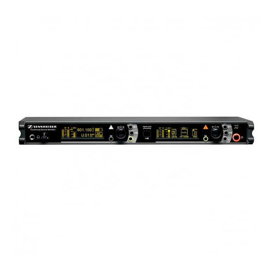
Page 9: Product Overview
Label with frequency range for daisy chaining The audio outputs marked with the number “1” output the audio signal of the left receiver of the twin receiver (as viewed from the front); the audio outputs marked with the number “2” output the audio signal... -
Page 10: Overview Of The Displays
For additional information, refer to page 11. Brightness control The display has an automatic brightness control. The brightness is dimmed after the last button press. With each new button press, the display lights up with full brightness. Triggers for dimming... -
Page 11: Reception Display
Product overview Reception display The reception display is permanently displayed. If you do not press a button on the receiver, the display will dim after 60 seconds (see page 9). RF level display “RF” for the antennas The left bargraph... -
Page 12: Status Display
The contents of the status display can be changed in the “Display” menu (see page 38). When pressing the jog dial 7, the status display is replaced by the oper- ating menu (see “Working with the operating menu” on page 24). - Page 13 Via the “Command” menu, you can configure the receiver so that – with the command button of the transmitter pressed – the audio signal is avail- able at only one of the outputs or at both (see “Configuring the audio outputs of the EM 3732 COM-II” on page 33).
-
Page 14: Putting The Receiver Into Operation
Putting the receiver into operation Fitting the device feet To ensure that the receiver cannot slip on the surface on which it is placed, four self-adhesive soft rubber feet are supplied. Do not fit the device feet when rack mounting the receiver. -
Page 15: Connecting The Antennas
The two antenna inputs allow you to connect either: • the two supplied antennas to the rear of the receiver (see next section) • the two supplied antennas to the front of the receiver (see “Mounting the antennas to the front of the rack” on page 14) or •... - Page 16 50-Ω coaxial cable. Ready-made coaxial antenna cables from Sennheiser are available as accessories with length of 1 m, 5 m and 10 m (see “Accessories” N O P Q R S on page 44). If you connect active antennas (e.g. A 3700, AD 3700) or antenna boosters (e.g.
-
Page 17: Daisy Chaining Receivers
– especially when you are using multi-outlet power strips or extension cables. The receiver has no mains switch. To connect the receiver to the mains: Connect the supplied mains cable to the 3-pin mains socket D. Plug the mains connector into the wall socket. -
Page 18: Connecting The Amplifier/Mixing Console
Via the operating menu of the corresponding receiver, adjust the level of the audio output to the input of the amplifier or mixing console (see “Adjusting the audio output level” on page 32). Connecting devices with AES3 digital input... -
Page 19: Connecting The Receivers To A Pc Via Ethernet
If you want to connect several receivers to the same Ethernet socket of your network, you require a standard 100Base-T Ethernet switch. Connect the supplied RJ 45 Ethernet cable to the RJ 45 socket for LAN connection and to your switch or network. -
Page 20: Using The Receiver
If you only want to use one of the two receivers of the EM 3732-II or EM 3732 COM-II, you can set the second receiver to standby mode (see “Setting a receiver to standby mode” on page 39). -
Page 21: Deactivating The Lock Mode
Using the receiver To monitor the audio signal of one of the two receivers of a twin receiver: Press the headphone button of the receiver whose audio signal you want to monitor. save % DEV 776.000 PEAK sync 01.01 BANK To simultaneously monitor the audio signals of both receivers of a twin µV... -
Page 22: Identifying Receivers Using The "Wireless Systems Manager" Software (Identifying Function)
“Identified” appears on the status display of the identified receiver: Identified After 60 seconds, the text disappears and the current status display is shown again. To change to the current status display before the end of the 60 seconds: button 6. Press the clock save 6.000... -
Page 23: Sorting Channels Using The "Wireless Systems Manager" Software
The sorting function of the “Wireless Systems Manger” software allows you change the channel assignment of the receivers at any time and to save this new channel assignment in a scene. Start the sorting function as described in the instruction manual of the “Wireless Systems Manger”... -
Page 24: Using The Operating Menu
Function of the menu Main menu “Tune” Sets a receiving frequency (this frequency is automati- cally stored in channel “01” of the frequency bank “U” (user bank)) “Bank.Ch” Switches between the frequency banks and between the channels of a frequency bank “Name”... -
Page 25: Working With The Operating Menu
The “Tune” menu is displayed together with its current setting. The Tune Bank position of a menu within the operating menu is illustrated by a graphic in the upper display margin (the “Tune” menu is on the very left of the operating menu). Selecting a menu Turn the jog dial until the icon of the desired menu is in the center of 776. -
Page 26: Overview Of The Menus
(1…6, U) and the channel (1...60) save + , - | / 0 1 2 3 4 5 6 + , - | / 0 1 2 3 4 5 6 7 8 9 * ; < = >... - Page 27 Booster AF O ooster AF Out Clock Audio output level Current audio Adjusting the audio output level output level (-10 dB to +18 dB) save 44.1 44.1 88.2 88.2 Comm Clock F Out Ext. Ext. Sampling rate of the...
- Page 28 Compander Disp Compander system Current compander Selecting the system compander system save pander Display IP-Ad button 8, the display automatically changes to the “Bank.Ch” menu (see page 25) After pressing the save – i.e. to the selected frequency bank.
- Page 29 Using the operating menu Selection mode Setting mode HiDyn plus Compander Disp 776.000 776.000 NAME B.CH pander Display IP-Ad Status display Current status Selecting the display contents of the status display save 192. 192. 192. 0192. 168. 168. 192. 049.
-
Page 30: Adjustment Tips For The Operating Menu
Setting the receiving frequency Via the “Tune” menu, you can: 776. B.Ch • set the receiver to a receiving frequency that can be freely selected 1.01 within the preset frequency range. The receiving frequencies are tune- Tune Bank able in 5-kHz steps within the switching bandwidth of 184 MHz max. - Page 31 60 channels to store your selection of receiving frequencies. Via Tune Bank the “Tune” menu, you can select the receiving frequencies to be stored in the frequency bank “U”. Change to the setting mode of the “Bank.Ch” menu and select the B.Ch...
- Page 32 The name is stored. The display changes to the selection mode of the operating menu. In order that the name is displayed on the status display, you may have to change the status display (see “Selecting the status display” on page 38).
- Page 33 F Out Clock “Ext.” means that the receiver will use one of above sampling rates from the external word clock generator. In this case, you first have to connect an external word clock generator to the BNC socket (see “Connecting an...
- Page 34 Command More These audio outputs can be switched on and off via a button on the trans- mitter – provided that the transmitter is also equipped with the command function (a separate power pack with command button is available for the SKM 5200 transmitter).
- Page 35 AF Out: pressed Command: on The active output lights up in the command display; muted outputs are not displayed (see “Command display (status display of the audio outputs AF and Command)” on page 12). Change to the setting mode of the “Command” menu.
- Page 36 Adjustment tips for the operating menu Scanning the frequency banks for interference-free channels Via the “Scan” menu, you can scan all frequency banks for free channels. Scan Comp Change to the setting mode of the “Scan” menu. Channel list The following selection appears: Scan new –...
- Page 37 Scan new Scan reset Press the jog dial 7. Bank 1 2 3 The number of free channels is reset to the maximum for all frequency Free 43 40 42 banks. Bank 4 5 6 U Free 32 31 33 60 Turn the jog dial to select a frequency bank.
- Page 38 Set all transmitters of a multi-channel system to different channels within the same frequency bank. Before putting the transmission links into operation, we recommend that you perform a scan in order to find a frequency bank with a sufficient number of free channels: Switch all transmitters off.
- Page 39 BANK sync Changing the IP address Via the “IP-Addr” menu, you can display and change the receiver’s IP address. The IP address consists of four bytes and each byte consists of up 192. 168. 00 1 to three digits (from 0 to 255). The receiver is factory-preset to dynamic...
- Page 40 The 12-digit MAC address is displayed. 00 1B 66 00 00:1B:66:00:00:01 00 01 Setting a receiver to standby mode You can set a receiver to standby mode and mute it. To do so, proceed as follows: 0 1B 6 00 0 01 Standby Rese Change to the setting mode of the “Standby”...
-
Page 41: Cleaning The Receiver
Cleaning the receiver Loading the factory-preset default settings Via the “Reset” menu, you can reset the current settings to the factory- preset default settings. andby Reset Change to the setting mode of the “Reset” menu. Reset to The query “Reset to factory defaults?”... -
Page 42: Additional Information
110 dB. is a wideband compander system which compresses the audio signal in the transmitter in a 2:1 ratio (related to dB) to lift it above the inherent noise floor of the RF link. In the receiver the signal is expanded... -
Page 43: Diversity Reception
The receivers operate on the “true diversity” principle: A receiving antenna receives not only the electromagnetic waves which reach it by a direct path, but also the reflections of these waves which are created in the room by walls, windows, ceilings and fittings. When these waves are superimposed, destructive interference occurs, which can also be called “field strength gaps”. -
Page 44: If A Problem Occurs
(see page 39). range If a problem occurs that is not listed in the above table or if the problem cannot be solved with the proposed solutions, please contact your local Sennheiser partner for assistance. To find a Sennheiser partner in your country, search at www.sennheiser.com under “Service & Support”. -
Page 45: Accessories
0.25 m directional Word clock daisy chain cable, 75 Ω, BNC, 087972 502196 AB 3700 antenna booster 0.25 m GZL AES 10 AES3 cable, 10 m, 110 Ω, 500887 A 5000 CP circularly polarized broadband 502432 antenna, passive double-shielded 004645... -
Page 46: Specifications
(peak deviation, 1 kHz +18 dBu to –10 dBu, adjustable in 1-dB steps (transformer balanced) AF output sockets 1 XLR-3 socket per receiver, 2 XLR-3 sockets per EM 3732 COM-II receiver 2 x 100 mW at 32 Ω Headphone output 10 Ω... - Page 47 0.4 A Power consumption with receiver switched on: max. 20 W (50 VA) with receiver switched off, booster supply voltage switched on: max. 9.5 W with receiver and booster supply voltage switched off: max. 4 W Mains connector 3-pin, protection class I, as per IEC/EN 60320-1 Dimensions W x D x H [mm] 436 x 215 x 44 (without rack mount “ears”)
-
Page 48: Manufacturer Declarations
This equipment has been tested and found to comply with the limits for a Class B digital device, pursuant to Part 15 of the FCC Rules. These limits are designed to provide reasonable protection against harmful interference in a residential installation. - Page 49 Bedienungsanleitung Istruzioni per l’uso Instruction manual Gebruiksaanwijzing Sennheiser electronic GmbH & Co. KG Notice d’emploi Am Labor 1, 30900 Wedemark, Germany Instrucciones de uso www.sennheiser.com Printed in Germany, Publ. 10/10, 542644/A01...