
Related Manuals for Yamaha MG8/2FX


Summary of Contents for Yamaha MG8/2FX
- Page 1 MIXING CONSOLE MIXING CONSOLE Owner’s Manual Owner’s Manual Making the Most Of Your Mixer Pages 6 to 14...
- Page 2 • If this device or the AC power adaptor should be dropped or damaged, immediately turn off the power switch, disconnect the electric plug from the outlet, and have the device inspected by qualified Yamaha service personnel. Connections • Before connecting the device to other devices, turn off the power for all devices.
- Page 3 Even when the power switch is in the “STANDBY” position, electricity is still flowing to the device at the minimum level. When you are not using the device for a long time, make sure you unplug the power cord from the wall AC outlet. The performance of components with moving contacts, such as switches, volume controls, and connectors, deteriorates over time. Consult qualifi ed Yamaha service personnel about replacing defective components.
-
Page 4: Table Of Contents
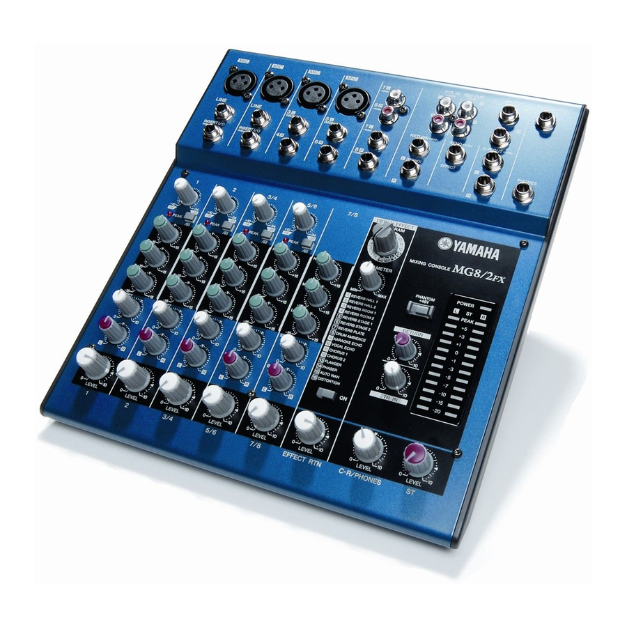
Introduction Introduction Thank you for your purchase of the YAMAHA MG8/2FX mixing console. The MG8/2FX is a compact unit offering up to eight input channels and incorporating high-quality internal digital effects. The mixer combines ease of operation with support for multiple usage environments. -
Page 5: Before Turning On The Mixer
Note that trace current continues to flow while the switch is in the STANDBY position. If you do not plan to use the mixer again for a long while, please be sure to unplug the adaptor from the wall outlet. MG8/2FX... -
Page 6: Making The Most Of Your Mixer
■ The Versatile Phone Jack Stereo/TRS phone plug Mono phone plug MG8/2FX This is the “consumer connector,” and the one that has been most commonly used on home audio gear for many years. Also known as “phono” jacks (short for “phonogram”), but the term isn’t used much these days—besides, it’s too easily confusable with... -
Page 7: How Do Balanced Lines Reject Noise
… nothing. A flat line. The signals cancel each other out. Normal-phase signal. Reverse-phase signal. Making the Most Of Your Mixer No signal. (Phase cancellation) MG8/2FX... -
Page 8: A Balanced Cable Has Three Conductors
+4 dB. Be sure to set these switches to match the level of the connected equipment. ● Inputs that feature a “Gain” control—such as the mono-channel inputs on your Yamaha mixer—will accept a very wide range of input levels because the control can be used to match the input’s sensitivity to the signal. More on this later. -
Page 9: Where Your Signal Goes Once It's Inside The Box
A stereo, mono, or bus master fader and the mixer’s main output level meter. There could be several master faders depending on the design of the mixer—i.e. the number of buses or outputs it provides. optimum Making the Most Of Your Mixer Master Section MG8/2FX... -
Page 10: The First Steps In Achieving Great Sound
Just remember that too much initial gain is bad too, because it will overload our channel circuitry and cause clipping. MG8/2FX... - Page 11 “peak zone” all the time. If the output level meters are peaking constantly you will need to lower the channel faders until the overall program falls within a good range—and this will depend on the “dynamic range” of your program material. Making the Most Of Your Mixer MG8/2FX...
-
Page 12: Internal And External Effect Mixes
“Y” end. One of the mono phone jacks carries the “send” signal to be fed to the input of the external processor, and the other carries the “return” signal from the output of the processor. MG8/2FX Channel To the input jack of the... -
Page 13: Making Better Mixes
2-dimensional (although some types of surround sound are actually very 3-dimensional), and instru- ments positioned right on top of each other will often get in each other’s way—particularly if they are in the same fre- quency range or have a similar sound. MG8/2FX... - Page 14 One of the biggest problems with too much boost is that it adds gain to the signal, increasing noise and potentially over- loading the subsequent circuitry. MG8/2FX 5-4. Ambience Judicious application of reverb and/or delay via the mixer’s effect busses can really polish a mix, but too much can “wash out”...
-
Page 15: Front & Rear Panels Channel Control Section
L (MONO) input only, and operates as a BAL control if you are inputting into both L and R inputs. To reduce noise, set the LEVEL Control knobs for unused channels all the way to the left (to the min- imum setting). MG8/2FX... -
Page 16: Master Control Section
If you supply a signal to the RETURN L (MONO) NOTE jack only, the mixer outputs the identical signal to both the L and R Stereo buses. MG8/2FX 2TR IN Control Adjusts the level of the signal sent from the 2TR IN jack to the Stereo bus. - Page 17 The switch lights up orange to indicate that it is on. With the (separately sold) YAMAHA FC5 foot switch connected, you can use your foot to toggle the digital effects ON and OFF.
-
Page 18: Input/Output Section
To the INSERT I/O jack Sleeve Ring To the output jack of the external processor MG8/2FX Channel Input Jacks (CH 7/8) Each of these channel pairs can be used to input a stereo source signal. For each pair, the odd-numbered channel inputs the L signal, and the even-numbered channel inputs the R signal. -
Page 19: Rear Section
FOOT SWITCH Jack This phone input jack can connect to the (separately sold) YAMAHA FC5 foot switch. With the foot switch connected, you can use your foot to toggle the digital effects ON and OFF. Pin 1: Ground Pin 2: Hot (+) Pin 3: Cold (–) -
Page 20: Setting Up
Setup Examples Synthesizer Rhythm Machine Microphone Guitar MG8/2FX NOTE To avoid causing damage to speakers, power up the devices in the following order: Peripheral devices → mixer → power amps (or powered speakers). NOTE Sound Source (CD, MD, DAT, Cassette, Video, etc.) -
Page 21: Mounting To A Microphone Stand
Loosen the angle adjustment wingnut ( 1 ), adjust the mixer’s angle as desired ( 2 ), and then tighten the wingnut securely ( 3 ). For more information, refer to the BMS-10A Owner’s Man- ual. Setting Up MG8/2FX... -
Page 22: Appendix
Power Consumption Dimensions (W × H × D) Weight Where 0 dBu = 0.775 V MG8/2FX Conditions (THD+N) 20 Hz - 20 kHz @+14dBu 10k ohms (CH1, 2) with Signal input CH LEVEL Control and ST Master LEVEL Con- trol at nominal level... - Page 23 Where 0 dBu = 0.775 V and 0 dBV= 1 V Specifications and descriptions in this owner’s manual are for information purposes only. Yamaha Corp. reserves the right to change or modify products or specifications at any time without prior notice. Since specifications, equipment or options may not be the same in every locale, please check with your Yamaha dealer.
-
Page 24: Dimensional Diagrams
Dimensional Diagrams REVERB HALL 1 REVERB HALL 2 REVERB ROOM 1 REVERB ROOM 2 REVERB STAGE 1 REVERB STAGE 2 REVERB PLATE DRUM AMBIENCE KARAOKE ECHO VOCAL ECHO CHORUS 1 CHORUS 2 FLANGER PHASER AUTO WAH DISTORTION Unit: mm MG8/2FX... -
Page 25: Block Diagram And Level Diagram
Appendix Block Diagram and Level Diagram MG8/2FX... - Page 26 MEMO MG8/2FX...
- Page 27 For details of products, please contact your nearest Yamaha representative or the authorized distributor listed below. Pour plus de détails sur les produits, veuillez-vous adresser à Yamaha ou au distributeur le plus proche de vous figurant dans la liste suivante.
- Page 28 Yamaha Pro Audio global web site http://www.yamahaproaudio.com/ Yamaha Manual Library http://www2.yamaha.co.jp/manual/english/ U.R.G., Pro Audio & Digital Musical Instrument Division, Yamaha Corporation © 2004 Yamaha Corporation WC70700 408CRAP12.3-01A0 Printed in China...