Cub Cadet 364, 365, 365L Operator's Manual
Zero turn tractor
Hide thumbs
Also See for 364, 365, 365L:
- Owner's manual (22 pages) ,
- Service manual (92 pages) ,
- Service manual (106 pages)
Table of Contents
Advertisement
OPERATOR'S MANUAL
IMPORTANT: READ SAFETY RULES AND INSTRUCTIONS CAREFULLY
Warning:
This unit is equipped with an internal combustion engine and should not be used on or near any unimproved forest-
covered, brush-covered or grass-covered land unless the engine's exhaust system is equipped with a spark arrester meeting
applicable local or state laws (if any). If a spark arrester is used, it should be maintained in effective working order by the operator.
In the State of California the above is required by law (Section 4442 of the California Public Resources Code). Other states may have
similar laws. Federal laws apply on federal lands. A spark arrester for the muffler is available through your nearest engine authorized
service dealer or contact the service department, P.O. Box 368023 Cleveland, Ohio 44136-9722.
CUB CADET CORP. P.O. BOX 368023 CLEVELAND, OHIO 44136-9722
PRINTED IN U.S.A.
Zero Turn Tractor
Models
364, 365 & 365L
FORM NO.
770-10099E.fm
(10/00)
Advertisement
Table of Contents

Related Manuals for Cub Cadet 364, 365, 365L


Summary of Contents for Cub Cadet 364, 365, 365L
- Page 1 Federal laws apply on federal lands. A spark arrester for the muffler is available through your nearest engine authorized service dealer or contact the service department, P.O. Box 368023 Cleveland, Ohio 44136-9722. CUB CADET CORP. P.O. BOX 368023 CLEVELAND, OHIO 44136-9722 PRINTED IN U.S.A.
-
Page 2: Table Of Contents
For future reference, please copy the model number and the serial number of the equipment in the space below. (Model Number) (Serial Number) CUB CADET CORP. P.O. BOX 368023 CLEVELAND, OHIO 44136 CALLING CUSTOMER SUPPORT If you have difficulty assembling this product or have any questions regarding the controls, operation or maintenance of this unit, please call the Customer Dealer Referral Line. -
Page 3: Important Safe Operation Practices
SECTION 1: IMPORTANT SAFE OPERATION PRACTICES WARNING: This symbol points out important safety instructions which, if not followed, could endanger the personal safety and/or property of yourself and others. Read and follow all instructions in this manual before attempting to operate this machine. Failure to comply with these instructions may result in personal injury. -
Page 4: Slope Operation
23. Muffler and engine become hot and can cause a burn. Do not touch. 24. Check overhead clearances carefully before driving under low hanging tree branches, wires, door openings etc., where the operator may be struck or pulled from the unit, which could result in serious injury. - Page 5 Service Safe Handling Of Gasoline: 1. To avoid personal injury or property damage use extreme care in handling gasoline. Gasoline is extremely flammable and the vapors are explosive. Serious personal injury can occur when gasoline is spilled on yourself or your clothes which can ignite. Wash your skin and change clothes immediately.
-
Page 6: Slope Gauge
CATCHER IS IN ITS PROPER PLACE. SECTION 2: SLOPE GAUGE Use this page as a guide to determine slopes where you may not operate safely. Do not operate your lawn mower on such slopes. KEEP HANDS AND FEET AWAY FROM ROTATING PARTS. -
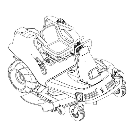
Page 7: Know Your Z-Series
SECTION 3: KNOW YOUR Z-SERIES NOTE: Reference to right or left hand side of the mower is observed from the operating position. Lift Handle Read this operator’s manual and safety rules before operating your Z-Series. Compare the illustrations in this manual with your unit to familiarize yourself with the location of various controls and adjustments. -
Page 8: Lift Handle
Electric PTO (Power Take-Off) Switch The PTO switch is located on the right control panel and it is used to control the engagement of the cutting blades. When the switch is up, the cutting blades are engaged. When the switch is down, the cutting blades are disengaged. -
Page 9: Parking Brake Pedal
• Battery: The BATTERY indicator light will illuminate any time the ignition key is in the ON position and the engine is not running. If it illuminates while the engine is running, then the battery is in need of a charge. Refer to the MAINTENANCE section of this manual for the proper battery charging procedure. -
Page 10: Operating Your Z-Series
SECTION 4: OPERATING YOUR Z-SERIES Gas and Oil Fill-Up Service the engine with gasoline and oil as instructed in the separate engine manual packed with your mower. Read instructions carefully. Your unit is shipped with oil; however, you IMPORTANT: MUST check the oil level before operating. Be careful not to overfill. - Page 11 • If safe for operation, walk the slope and look for hazards such as rocks, mounds, ruts, stumps, or other irregularities. • After removing debris and identifying irregularities of the slope, back the Z-Series up the steepest slope you intend to work. If it cannot negotiate the slope in reverse, the slope is too steep.
-
Page 12: Making Adjustments
Release Handles = Neutral / Stop Full Right Forward And Full Left Back = Zero Turn Left Right Forward And Left Neutral = Left Turn SECTION 5: MAKING ADJUSTMENTS Adjusting the Mower Deck Height • To push or pull the lift lever, depress and hold the button. -
Page 13: Steering Adjustment
Checking the Brake Adjustment • Position the Z-Series on a level surface and move the throttle lever to the slowest position (turtle). • Stop the engine, remove the key from the ignition, and engage the parking brake. • Release both hydraulic relief levers. •... -
Page 14: Maintaining Your Z-Series
• Remove bolts that secure linkage to upper control handles and lower control arms. The shock absorbers should remain connected to linkage. See Figure 12. Hex Bolt Jam Nuts Hex Bolt Figure 12 • Insert quarter inch by seven inch pin or equivalent through the top and bottom alignment holes of the control arms to secure arms at positive neutral. -
Page 15: Fuel Tank
Deck Lift Pivot Grease Fittings Lift Handle Grease Fitting Control Tower Grease Fittings Engine Refer to the separate engine manual for engine maintenance instructions. Service air cleaner every 25 hours under normal conditions. Clean every few hours under extremely dusty conditions. To service the air cleaner, refer to the separate engine manual. - Page 16 Checking Hydraulic Oil Check the oil level of hydraulic units only when the engine is OFF. During initial break-in (first five hours of operation), check oil before each use and after every hour of operation. During normal operation, check oil after 50 hours of operation.
-
Page 17: Removing The Drive Belt
• Slide the boot cover all the way up (toward the drive handles) to access the drive handle bolts. • Remove drive handle bolts, drive handles, and rubber boot. • Remove the four bolts securing the retaining plate to the control tower cover. •... -
Page 18: Mower Deck
• Carefully pull the belt up and over the right hydrostatic cooling fan and then lift up and over the left hydrostatic cooling fan. • Pull the drive belt out of the unit. Installing Drive Belt • Set the parking brake and insert drive belt up and over the left and right hydostatic cooling fans. -
Page 19: Removing The Mower Deck
Front Lift Rods Figure 21 Removing The Mower Deck WARNING: Do not remove deck immedi- ately after operating the tractor. Allow the engine and other moving parts ample time to cool down. • Position the Z-Series on a hard flat surface and engage the parking brake. -
Page 20: Installing The Mower Deck
44” Deck 54” Deck Figure 25 Installing Mower Deck Belt • Remove the mower deck and the old mower deck drive belt from the mower deck. • Install and route the new belt according to the routing diagram. See Figure 26 or Figure 27. •... -
Page 21: Troubleshooting
Mower Blades WARNING: The mower blades are sharp and can cause severe injury. Always protect hands by wearing heavy leather work gloves to grasp blades. Block Of Wood Blade Figure 29 SECTION 8: TROUBLESHOOTING Trouble Possible Cause(s) Engine fails to start PTO switch engaged. -
Page 22: Parts List
Models 364, 365, & 365L... - Page 23 Models 364, 365, & 365L REF. PART DESCRIPTION 731-3263 Control Handle 712-3004A Flange Lock Nut 5/16-18 710-0451 Carriage Bolt 5/16-18 731-3185 Bellow 735-0251 Foot Pad 710-0642 Hex Washer Screw 1/4-20 x .75 703-2648 Bellow Retainer Bracket 712-0431 Flange Lock Nut 3/8-16 703-2807B Foot Pad Mounting Bracket 710-3168...
- Page 24 Models 364, 365, & 365L 13 14...
- Page 25 Models 364, 365, & 365L REF. PART DESCRIPTION 603-0649 Parking Brake Shift Ass’y 714-3004 Cotter Pin 710-3178 Carriage Bolt 3/8-16 x .75 741-0324 Hex Flange Bearing .506 ID x .590 703-3400 Brake Mounting Bracket 747-3404 Connecting Brake Rod 714-0104 Cotter Pin 710-0134 Carriage Screw 1/4-20 x .62 712-3027...
- Page 26 Models 364, 365, & 365L...
- Page 27 Models 364, 365, & 365L REF. PART 603-0340 Bellcrank Ass’y Upper LH 603-0341 Bellcrank Ass’y Upper RH 603-0342 Bellcrank Ass’y Lower LH 603-0343 Bellcrank Ass’y Lower RH 603-0647 Support Ass’y Tower 603-0410 Rod Ass’y Control RH 603-0411 Rod Ass’y Control LH 710-0216 Hex Cap Screw 3/8-16 x .75 710-3005...
- Page 28 Models 364, 365, & 365L...
- Page 29 Models 364, 365, & 365L REF. PART DESCRIPTION 737-3069 Pipe Plug 737-3070A Pipe Dipstick 603-0639 Hydraulic Tank Assembly 727-3116 Connection Fitting 721-0223 Seal 738-0940 Drain Plug 727-3120 Inlet Tube LH 727-3155 Tee Fitting 727-3154 Outlet Hose RH 727-3121 Inlet Tube RH 727-3153 Outlet Hose LH 710-0216...
- Page 30 Models 364, 365, & 365L REF. PART DESCRIPTION 618-3110A Drive Ass’y Complete 712-3004A Hex Flange Lock Nut 5/16-18 715-0136 Spiral Pin 3/16 x 1.25 717-3396 Spur Gear 14T 717-3455 Hydro Transmission 718-3053 Parking Brake Lever 721-0343 O-Ring 2.0 Dia. 727-3125 Cap Nut 3/8...
- Page 31 Models 364, 365, & 365L REF. PART DESCRIPTION 618-3110A Drive Ass’y Complete 611-3012 Axle Assembly 710-0852 Ribbed Neck Stud 618-3106 Carrier Assembly, Output 618-3107 Gear Assembly, 51T Internal & 20T 618-3109 Housing Ass’y 710-1342 Hex Washer Screw 1/4-20 x 1-1/8 711-1048 Brake Shaft 712-3027...
- Page 32 Model 364...
- Page 33 Model 364 REF. PART DESCRIPTION 751-3141 Oil Drain Extension Hose 751-3142 Oil Drain Cap 751-3140 Oil Drain 710-3009 Tap Screw #10-24 x .75 746-3070 Throttle Cable 746-3069 Choke Cable 712-0161 Hex Lock Nut #10 - 24 710-0751 Hex Cap Screw 1/4-20 x .620 736-3006 Lock Washer 1/4 x 3/4 736-0270...
- Page 34 Model 365...
- Page 35 Model 365 REF. PART DESCRIPTION 751-3141 Oil Drain Hose 751-3142 Oil Drain Cap 751-3140 Oil Drain 710-3009 Screw #10-24 x .750 746-3070 Throttle Control Cable 40.5” 746-3066 Choke Control Cable 38.0” 710-3008 Hex Cap Screw 5/16-18 x .75 726-3008 Cable Clip Heat Shield 712-3004A Hex Lock Nut 5/16-18 749-3048...
- Page 36 Model 365L...
- Page 37 Model 365L REF. PART DESCRIPTION 751-3141 Oil Drain Hose 712-3004A Flange Lock Nut 5/16-18 703-3023 Mounting Muffler Bracket 710-3008 Hex Cap Screw 5/16-18 x .75 726-0205 Hose Clamp 751-0535 Fuel Line Hose 710-0216 Hex Cap Screw 3/8-16 x .75 710-3009 Screw #10-24 x .750 746-3071 Throttle Control Cable 53.0”...
- Page 38 Models 364 & 365...
- Page 39 Model 364 & 365 REF. PART DESCRIPTION 629-3070 Wire Harness, Main - Not Shown 723-0455 Foam Protector, Indicator Light 710-3013 Hex Cap Screw 1/4-20 x .50 703-2809 Bracket, Indicator Bulb Mtg. 712-3027 Nut, Hex Flange Lock, 1/4-20 725-1718 Relay 703-2836 Bracket, Headlight Mtg.
- Page 40 Model 365L...
- Page 41 Model 365L REF. PART DESCRIPTION 629-3071 Wire Harness, Main - Not Shown 723-0455 Foam Protector, Indicator Light 710-3013 Hex Cap Screw 1/4-20 x .50 703-2809 Bracket, Indicator Bulb Mtg. 712-3027 Nut, Hex Flange Lock, 1/4-20 725-1718 Relay 703-2836 Bracket, Headlight Mtg. 710-0134 Carriage Screw 1/4-20 x .62 725-3164A...
- Page 42 Models 364, 365, & 365L...
- Page 43 Models 364, 365, & 365L REF. PART DESCRIPTION 757-0375B Seat Ass’y 757-3009 Seat Arm Ass’y (If Equipped) 731-3154 Seat Slide 710-1260A Hex Washer Screw 5/16-18 x .750 738-0372 Shoulder Spacer 720-0190 Height Adjuster Knob 732-3098 Spring Index 712-3004A Flange Lock Nut 5/16-18 603-0294 Seat Base Bracket Ass’y 710-0788...
- Page 44 Models 364, 365, & 365L...
- Page 45 Models 364, 365, & 365L REF. PART DESCRIPTION 711-0642A Handle Button 731-3158 Handle Deck Lift Grip 732-3097 Compression Spring 747-3405 Front Lift Rod 738-0507B Shoulder Screw .500 Dia x .434 710-0216 Hex Cap Screw 3/8-16 x .75 603-0422 Shaft Mounting Bracket - LH 603-0370 Pivot Link Bearing Ass’y 603-0313...
- Page 46 Models 364, 365, & 365L REF. PART 712-3075 Hex Lock Nut, 1.0-14 736-0274 Flat Washer 603-0389A Pin Ass’y, Pivot 737-3090 Adapter, 1/8 NPTF x 1/8 NPTF 737-3072 Grease Fitting, 65° w/Extension 712-0431 Hex Flange Lock Nut, 3/8-16 712-0229 Push Nut, 3/8 ID 710-3178 Carriage Bolt, 3/8-16 x .75 710-0514...
- Page 47 Model 364 REF. PART DESCRIPTION 712-0251 Retainer Nut 3/8-16 603-0720B Frame Assembly 712-0455 Retainer Nut 3/8-16 712-0431 Flange Lock Nut 3/8-16 710-0216 Hex Cap Screw 3/8-16 x .75 710-3144 Hex Cap Screw 3/8-16 x 2.0 712-3004A Flange Lock Nut 5/16-18 736-0258 Flat Washer .385 x 1.0 x .135 749-3087...
- Page 48 Models 365 & 365L REF. PART DESCRIPTION 712-0251 Retainer Nut 3/8-16 603-0720B Frame Assembly 712-0455 Retainer Nut 3/8-16 712-0431 Flange Lock Nut 3/8-16 710-0216 Hex Cap Screw 3/8-16 x .75 710-3144 Hex Cap Screw 3/8-16 x 2.0 712-3004A Flange Lock Nut 5/16-18 736-0258 Flat Washer .385 x 1.0 x .135 749-3062...
- Page 49 Models 364, 365, & 365L REF. PART DESCRIPTION 722-0265 Foam 2.04 x 3.50 x .62 710-1260A Hex Washer Screw 5/16-18 x .75 736-0231 Flat Washer .344 ID x 1.125 OD 651-3004 Tank Assembly 4.0 Gallon 703-3490 Fuel Tank Mounting Bracket 712-0431 Flange Lock Nut 3/8-16 710-0216...
- Page 50 Model 364...
- Page 51 Model 364 REF. PART DESCRIPTION 732-0556 Extension Spring .94 OD x 7.57 712-3006 Hex Nut 1/4-20 710-0597 Hex Cap Screw 1/4-20 x 1.0 710-3151 Hex Cap Screw 5/8-18 x 4.25 736-0290 Flat Washer 5/8 ID x 1.0 OD 741-0524 Bearing .625 ID x 1.574 OD 754-3091 Belt 716-3020...
- Page 52 Model 365 & 365L 48 31 45...
- Page 53 Model 365 & 365L REF. PART 720-0241 Wing Nut Knob 703-2817 Belt Cover LH 703-2816 Belt Cover RH 747-3306 Idler Spring Mounting Rod 738-0380 Shoulder Screw 3/8-16 756-3106 Pulley 712-0431 Flange Lock Nut 3/8-16 710-0521 Hex Cap Screw 3/8-16 x 3.0 736-0258 Flat Washer .385 ID x 1.0 OD 756-3105...
- Page 54 Model 365 & 365L REF. PART DESCRIPTION 732-0772 Extension Spring 1.25 OD x 11.5 Lg 711-0509 Spring 712-3007 Hex Jam Nut 5/16-18 712-0116 Jam Lock Nut 3/8-24 711-1059 Ferrule 736-0159 Washer 5/16 710-1207 Hex Cap Screw 5/16-18 x 3.50...
- Page 55 Models 364, 365, & 365L 629-3071 629-3070...
-
Page 56: Cleveland, Ohio
There is no other express warranty. Contact your authorized Cub Cadet servicing dealer who sold you your Cub Cadet equipment. If this dealer is not available, see the Consumer Yellow Pages under “lawn mowers” for the name of a dealer near you.