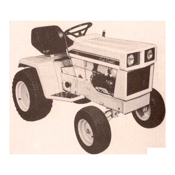
Cub Cadet 108 Operator's Manual
Tractors and rotary mowers
Hide thumbs
Also See for 108:
- Operator's manual (27 pages) ,
- Owner's manual (12 pages) ,
- Service manual (152 pages)
Table of Contents
Advertisement
Advertisement
Table of Contents

Related Manuals for Cub Cadet 108


Summary of Contents for Cub Cadet 108
- Page 2 Assembled in this manual are operation, cation, maintenance International Cub Cadet 86, 108, 128, 129, 149, and 169 Tractors. The material has been prepared in detail to help you better understand the correct care and efficient operation of your tractor. Before you operate the tractor, study this manual care-fully.
-
Page 6: Left And Right
Serial No. 500718 and above. A variety of extra equipment and accessories isavailable. Where operating and maintaining instruc- tion is required, it is included in the instruction for operating and maintaining the tractor. the instructions for equipment not on your tractor. This manual is for tractors with Serial No. - Page 7 This symbol is used to call your attention to instructions concerning your personal safety. Be sure to observe and following these instructions. Disengage all clutches and shift into neutral before starting the engine. Disengage power to any attachments engine before leaving operator's seat or making any repairs or adjustments.
- Page 8 Your Cub Cadet Tractor acquaint yourself with attempting to start or operate the tractor. Instruments and controls on the International Cub Cadet 86, 108, and 128 Tractors. Choke Clutch-brake Brake Throttle Creeper Gearshiftlever Charge Lighting Electricliftcontrolswitch* Front Ignition Lift handle...
- Page 9 Instruments and controls on the International Cub Cadet 129, 149, and 169 Tractors. Speed Choke Charge Throttle Brake Release Hydraulic Brake Lighting Ignition Front Hour Lifthandlecamstop Electrict meter- pedal. pedal power control control indicator lever. 13. switch. lever switch lift*...
- Page 10 Lubrication Tires. Fuel System. 1. Fuel tank filler cap 2. Fuel tank 3. Carburetor (not seen) THROTTLE LEVER This lever controls the speed of the engine. When set in a given position, it will maintain engine speed. When using power take-off operated equipment, best performance is achieved with the throttle lever in the "FAST"...
- Page 11 On the I nternational Cub Cadet 129, 149, and 169 Tractors the speed control neutral wher the clutch-brake pedal is pressed all the way down.
-
Page 12: Fuel System
International Cub Cadet 86 Tractor. 1. Governor control rod2. Idle adjustment screw3. Throttle stop screw4. High speed adjustment screw5. Fuel shut-off valve6. Fuel line7. Air cleaner International Cub Cadet 108, 128, 129, 149, and 169 Tractors. - Page 13 CARBURETOR ADJUSTMENTS CAUTION! Be sure the brake pedal is in the locked position, neutral, and the mower before adjusting the carburetor. Adjusting the High-Speed Adjustment Screw Turn the high speed adjustment screw counter- clockwise approximately two turns from the closed position and start the engine.
-
Page 14: Locking The Brake
Adjusting the seat. Before starting the tractor, most comfortable driving position. Tile the seat forward over the steering wheel, loosen the four cap screws in the seat support, and slide the seat assembly forward or rearward to the position wh ich is most comfortable for the operator. Retighten the cap screws after the seat is adjusted. -
Page 15: Clutch-Brake Pedal
Always be sure the rear wheels are free to turn. Under any adverse conditions, do not attempt to International Cub Cadet 86, 108 and 128 Tractors free the tractor suddenly engaging the clutch. instead of going forward. -
Page 16: Speed Table
Do not rest your foot on the brake pedal while driving the tractor as this would cause the speed control lever to return to the "N" position. DRIVING THE TRACTDR International Cadet 86, 108 and 128 Tractors DRIVE SPEED TABLE Miles Per Hour... -
Page 17: Driving The Tractor
International Cub Cadet 129, 149, and 169 Tractors STARTING THE TRACTOR 1. Depress the brake pedal and release the brakelock. Move the throttle lever to the position wherethe engine operates best for the load to be handled. 2. Start the tractor in motion by moving the speed... -
Page 18: Three-Point Hitch
1. Lift lever 2. Draw bar 3. Three-point hitch Orawbar and three-point hitch shown on International Cub Cadet 86 Tractor. DRAWBAR Orawbar equipment must be hitched to the tractor only at the hitch hole in the drawbar. THREE-POINT HITCH When the tractor has a three-point hitch, equip- ment adaptable to this hitch is raised and lowered with the lift handle or power lift control. - Page 19 Always cover the power take-off exposed shaft with the guard when the power take-off is not being used. International Cub Cadet 86, 108 and 128 Tractors OPERATING WITH THE TRACTOR 1. Move the throttle speed. 2. Depress the pedal and move the transmission gearshift lever to the neutral position.
- Page 20 4. Clutch control handle 5. Turnbuckle fully engaged (clutch position) After obtaining the proper clear- Periodically lubricate the bushing lever bracket with a few drops of engine oil. lift is available on all Cub Cadet control the clearance in the...
-
Page 21: Electric Lift
OPERATING INSTRUCTIONS 1. Float lockout pin (optional)2. Electric lift unit 3. Pivot pin The electric lift is operated by a control switch on upper right-hand corner of the instrument panel. To raise the implement push upward on control switch until desired height is reached, then release the switch. - Page 22 1. Float lockout pin (optional)2. Hydrostatic drive unit3. Cotter pin The hydraulic lift is ready to operate when the engine is running. OPERATING INSTRUCTIONS The hydraulic control lever is spring loaded. To raise the equipment move the lever back, toward the tractor seat.
-
Page 23: Engine Cooling
ENGINE COOLING This tractor has an air cooled engine. Air must be able to circulate freely around the engine, through the screen, shroud, and over the fins of the cylinder head and cylinder block. Keep these areas free of accumulated dirt and trash or engine will overheat and result in damaged moving parts. -
Page 24: Electrical System
HOUR METER The International Cub Cadet 169 is equipped with an hour meter, which is located on the left side of the tractor parallel to the air cleaner. It indicates the actual hours of engine operation, enabling the... -
Page 25: Motor-Generator
MOTOR-GENERATOR BELT Adjusting the Motor-Generator Belt Loosen the motor-generator brace bolt and mount- ing bolts. Move the generator away from the engine until the tension on the belt is correct. NOTE: Under no circumstances should a pry bar be used on the motor-generator tension as damage to the bearings will result. -
Page 26: Rear Tires
REAR TIRES 6-12 rear tires are standard equipment International Cub Cadet 86 and 108 Tractors. 23 x 8.50-12 high floatation equ ipment on the I nternational 129, and 149 Tractors. They are also available as... - Page 27 CARE OF TIRES Avoid stumps, stones, deep ruts, curbs, and other hazards. Cuts in tires should be repaired immedi- ately as neglect decreases the tire life. Keep tires free from oil and grease as both destroyrubber. After using the tractor for spraying use water to remove any chemicals that may be on the tires.
-
Page 28: Front Wheel Toe-In
FRONT QUICK ATTACHING This latch is used for front and center mounted equipment. Refer to the equipment manual for proper instructions. FRONT WHEEL TOE-IN 1. Front quick attaching latch Front wheel adjustments. 1. Wheel hub Front wheel adjustments. LATCH The front wheel toe-in dimension is approximately 1/8-inch measure for proper toe-in, make a chalk mark on the centerline of each tire the same height from the... -
Page 29: Adjusting The Clutch
The disc brakes should start to engage when the pedal is pressed down to a position where the engine clutch starts to release. International Cub Cadet 86, 108 and 128 Tractors Push the pedal down until the clutch just begins to release. This transmission into third gear and rocking the tractor back and forth. -
Page 30: Clutch-Brake
ADJUSTING THE BRAKES To adjust the brakes block the front wheels se- curely and raise the tractor so the rear wheels are off the ground. CAUTION! Be careful and take neces- sary precautions when raising tractor off the ground. With the rear wheels off the ground and the brake pedal in the locked position, the brake settings should be equalized as follows: Disconnect the left brake rod at the pinned end,... - Page 31 NOTE: The brakes must not engage before the pedal is within the maximum distance of 1-3/16- inches. International Cub Cadet 129, 149 and 169 Tractors "" "" "" """ (-"-.. r-l~ -r::;:::-...
-
Page 32: Removing From Storage
On all gear driven International Disengage P.T.G. clutch. Table". charged battery and properly or operate at high speed CAUTION J Keep doors lease brake pedal lock machine outside the storage room before Check air pressure in tires. Cub Cadet wide open or re- move... - Page 33 When you purchased your tractor, you probably had it completely equipped for your particular needs at the time. However, later you may wish to obtain some of the equipment or accessories shownbelow. These items and other allied equipment can purchased from, I nternational Harvester dealer.
-
Page 34: Troubleshooting
Brake Clutch Incorrect drags slipping timing (Models faulty ignition. 108, Insufficient cool air, dirty air intake screen, shroud, or cooling fins. Speed control out of adjustment (Models 129, 149, and 169) TROUBLE SHOOTING OPERATES IRREGULARLY wrong type. Clean, reset the gap to .025 inch, or replace. -
Page 35: Engine Oil
NOTE" Check the oil level only while the engine is stopped. NOTE: On the Cub Cadet 86 Tractor the oil filler cap has the oil level gauge attached and is located on the right side of the tractor. -
Page 36: Transmission Oil Filter
ENGINE OIL -Continued 1. Oil filler cap and oil level gauge -Cub Cadet 86 Tractor 1. Oil filler cap and oil level gauge -All models except the Cub Cadet 86 Tractor lUBRICATION Keep your supply of lubricating clean and free from containers. - Page 37 129, 149, and 169 Tractors Transmission Models 129,149, and 169 Tractors Transmission Models 86, 108, and 128 Tractors Creeper drive hous- ing Models 86, 108 and 128 Tractors Steering gear hous- Yearly ing All models Steering knuckles All models Change Capacity Above +32°F.
- Page 38 LUBRICATION International Cub Cadet 86, 108 and 128 Tractors GUIDE ';:;...
- Page 39 3 -Front axle pivot pin. 4 -Engine crankcase. 5 -Power take-off shafting bearing. LUBRICATION GUIOE International Cub Cadets 86, 108 and 128 Tractors -After Every 10 Hours of Operation Check the oil (with the engine stopped) and add sufficient new oil to bring it to the "FU LL" mark on the gauge. Do not overfill.
-
Page 40: Lubrication Guide
10 -Drain plug. 11 -Steering gear housing. Miscellaneous LUBRICATION GUIDE International Cub Cadet 86, 108 and 128 Tractors -Periodic Check the oil level periodically. the level plug (6) on the rear of the transmission case. Check the oil level periodically. - Page 42 7. Transmission oil filter. Transmission Oil level and filler plug LUBRICATION GUIDE International Cub Cadet 108, 149, and 169 Tractors -After Every 10 Hours of Operation Check the oil (with the engine stopped) and add sufficient new oil to bring it to the "FU LL" mark on the gaugE:. Do not overfill.
- Page 43 Rear Power take-off shaft spline dimensions (International Cub Cadet 86, 108, and 128 Tractors). LUBRICATION GUIDE International Cub Cadet 129, 149, and 169 Tractors -Periodic Once a year, apply two strokes of the lubricator, using I H 251 H EP grease or equivalent #2 multi-purpose grease.
-
Page 45: Specifications
Headlights -all glass, sealed SPECIFICATIONS Model 86 Model 108 Model 128 Battery Battery Battery 025 in. gap 025 in. gap .025 in. gap .025 in. gap .025 in. gap .025 in. gap 020 in. gap .020 in. gap .020 in. gap .020 in. gap .020 in. gap .020 in. gap... - Page 47 MOWERS (38, 44, and 50-inch, 3 spindle) with wide-oval runners Quick-attachable mounting...
- Page 48 Your new rotary mower today's exacting operating requirements. The ease operation ability conditions lighten your work and shorten your hours on the job. Your are urged to consult Harvester dealer concerning unusual field condi- tions or special applications. Let the experience of your dealer and the organization associated with him serve you.
- Page 49 International Cub Cadet Tractors number 400,001 and higher, and are quick detach- able by the use of two spring loaded handles and two bayonet type hangers. The mower extends beyond the tractor wheels to permit cutting close to shrubbery, trees, fences, buildings, drive and walkway edges, etc.
- Page 50 CAUTIONI This symbol is used to call your attention to instructions concerning your personal safety. Be sure to observe and follow these precautionary instructions. The discharge shield on the attached at all times while operating the mower. Keep the machine in good operating condition and keep safety devices in place.
- Page 51 1. Power take-off clutch lever 2. Mower support brackets 3. Mower support clevises 4. Runners 5. Lift stop 6. Hydraulic lift handle 7. V-belt tension bolt 8. Extension spring measurement 9. Front hanger cover 10. Quick hitch 11. Power take-off clutch rod 12.
-
Page 52: Stopping The Mower
1. Power take-off clutch lever2. Mower support brackets3. Mower support clevises4. Runners5. Lift stop6. Electric lift control switch*7. V -belt tension bolt *Optional Equipment THE MOWER the engine operating at idle speed, slowlyengage the power take-off clutch lever. Advancethe throttle to full throttle. STOPPING THE MOWER Disengage the power take-off clutch lever (to therear... -
Page 53: Level Adjustment
LEVEL ADJUSTMENT -Continued 1. Support brackets2. Support clevises 38-inch mower shown. CAUTION! Be sure to turn off the engine, remove the ignition key, set the brake pedal in the locked position, and disengage the power take-off clutch. Set the lift handle stop for the desired mowing height. - Page 54 V-BEL T Main Drive Belt-(38-inch mower) The main drive V -belt is adjusted for tension by the V-belt tension bolt. Tighten the locknut to increase belt tension and loosen the locknut to decrease the belt tension. When installing a new belt, the initial tension is obtained by adjusting the bolt so the distance measures approximately 3-1 /2-inches from the cen-...
- Page 55 V-BEL T Main Drive Belt-(44-inch and 50-inch mowers) main drive V-belt is properly tensioned whenthe idler ratchet is positioned decal on the front cover of the lift frame. To adjust the belt for proper tension tighten the V-belt tension bolt so the notch on the idler ratchet is in line with the slot on the cover as shown in the illustration.
-
Page 56: Height Of Cut
HEIGHT OF CUT Set the lift stop for the desired height of cut. Refer to the Tractor Operator's respect to the type of I ift system on the tractor. CLEANING Clean the underside of the mower at the end of the mowing season and when the build-up material on the underside is noticed. - Page 67 No accident-prevention program can be suc- cessful without the wholehearted co-operation of the person who is directly responsible for the operation of equipment. To read accident reports from all over the country is to be convinced that a large number of accidents can be prevented only by the operator anticipating the result before the...