Crown ce 4000 Operation Manual
Ce series
Hide thumbs
Also See for ce 4000:
- Service manual (140 pages) ,
- Reference manual (32 pages) ,
- Specifications (2 pages)
Table of Contents
Advertisement
Quick Links
CE Series
Operation Manual
CE 4000
Obtaining Other Language Versions: To obtain information in another language about the use of this product, please contact your
local Crown Distributor. If you need assistance locating your local distributor, please contact Crown at 574-294-8000.
This manual does not include all of the details of design, production, or variations of the equipment. Nor does it cover every possible
situation which may arise during installation, operation or maintenance.
The information provided in this manual was deemed accurate as of the publication date. However, updates to this information may have
occurred. To obtain the latest version of this manual, please visit the Crown website at www.crownaudio.com.
Trademark Notice: Amcron, BCA and Crown are registered trademarks of Crown International. Other trademarks are the property
of their respective owners.
Some models may be exported under the name Amcron.®
©2003 by Crown Audio Inc. P.O. Box 1000, Elkhart, Indiana 46515-1000 U.S.A. Telephone: 574-294-8000
127393-5
11/03
Advertisement
Table of Contents

Related Manuals for Crown ce 4000


Summary of Contents for Crown ce 4000
- Page 1 Trademark Notice: Amcron, BCA and Crown are registered trademarks of Crown International. Other trademarks are the property of their respective owners. Some models may be exported under the name Amcron.® ©2003 by Crown Audio Inc. P.O. Box 1000, Elkhart, Indiana 46515-1000 U.S.A. Telephone: 574-294-8000 127393-5 11/03...
-
Page 2: Important Safety Instructions
• Consult the dealer or an experienced radio/TV technician for help. QUALIFIÉ SEULMENT. CE 4000 Power Amplifi er IMPORTANT The CE 4000 amplifi er requires Class 2 output wiring in stereo. Class 1 output wiring is required in Bridge mode. WATCH FOR THESE SYMBOLS: The lightning bolt triangle is used to alert the user to the risk of electric shock. - Page 3 CE 4000 Power Amplifi er Crown International, Inc. Issued By: Crown International, Inc. 1718 W. Mishawaka Rd. Elkhart, IN 46517 U.S.A. European Representative’s Name and Address: Nick Owen 19 Clos Nant Coslech Pontprennau Cardiff CF23 8ND United Kingdom Equipment Type: Commercial Audio Power Amplifi ers...
-
Page 4: Table Of Contents
4.3 Back Panel Controls and Connectors... 12 5 Advanced Features and Options ...13 5.1 Protection Systems... 13 5.1.1 Anti-Clip Limiters ... 13 page 4 CE 4000 Power Amplifi er 5.1.2 Fault...13 5.1.3 High-Pass Filter ...13 5.2 Circuit Design ...13 5.2.1 BCA ...13 5.2.2 Switching Power Supply with PFC ...13... -
Page 5: Welcome
• Weighs just 33.3 pounds (15.1 kg). service for which they were designed. 1.2 Unpacking Your Amplifi er In addition, the CE 4000 amplifi er includes a Please unpack and inspect your amplifi er for number of features which require some expla-... -
Page 6: Setup
NOTE: When transporting, amplifi ers should be supported at both front and back. Figure 3.1 Dimensions CE 4000 Power Amplifi er 3.3 Ensure Proper Cooling When using an equipment rack, mount units directly on top of each other. Close any open spaces in rack with blank panels. -
Page 7: Choose Input Wire And Connectors
CE 4000 Power Amplifi er 3 Setup 3.4 Choose Input Wire Balanced Line Unbalanced Line and Connectors Crown recommends using pre-built or profes- sionally wired, balanced line (two-conductor plus shield), 22-24 gauge cables and connec- tors. Depending upon which amplifi er input... -
Page 8: Choose Output Wire And Connectors
Wire Size 16 gauge 14 gauge 12 gauge 10 gauge 8 gauge 6 gauge Figure 3.6 Barrier Block Output Connector Wiring Figure 3.7 Binding Post Output Connector Wiring CE 4000 Power Amplifi er OUTPUTS CH-2 CH-1 OUTPUTS CH-2 CH-1 OUTPUTS CH-2... -
Page 9: Wire Your System
CE 4000 Power Amplifi er 3 Setup 3.6 Wire Your System 3.6.1 Stereo Mode Typical input and output wiring is shown in Figure 3.8. INPUTS: Connect input wiring for both channels. OUTPUTS: Maintain proper polarity (+/-) on output connectors. Connect Channel-1 positive (+) speaker load to Channel-1 positive terminal of amp;... -
Page 10: Connect To Ac Mains
Do not short the ground lead of an output cable to the input signal ground. Remember: Crown is not liable for This may form a ground loop and cause damage that results from overdriving oscillations. other system components. CE 4000 Power Amplifi er Operation Manual... -
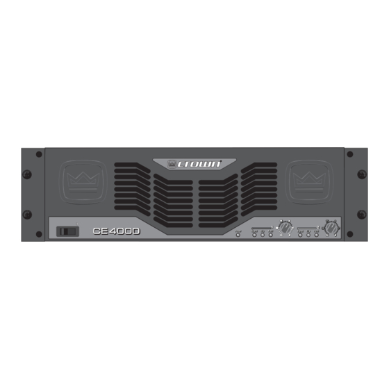
Page 11: Front Panel Controls And Indicators
CE 4000 Power Amplifi er 4 Operation 4.2 Front Panel Controls and Indicators A. Power Switch Amplifi er is on when the switch is in the “I” position. B. Cooling Vents Front-to-rear forced airfl ow. C. Power Indicator Green LED indicates amplifi er has been turned on and AC power is available. -
Page 12: Back Panel Controls And Connectors
Outputs N. Sensitivity Switch Allows selection of .775V, 1.4V or 26-dB sensitivity. Figure 4.2 Back Panel Controls and Connectors CE 4000 Power Amplifi er O. Mode Switch Allows selection of Stereo or Bridge operation. P. Low-Pass Filter Switch Allows selection of Flat, 80 Hz or 100 Hz roll-off. -
Page 13: Advanced Features And Options
CE 4000 Power Amplifi er 5 Advanced Features and Options NOTE: For detailed information about these Crown amplifi er features, please consult the Crown Amplifi er Application Guide, available on the Crown website at www.crownaudio.com. 5.1 Protection Systems Your Crown amplifi er provides extensive pro- tection and diagnostic capabilities, including built-in anti-clip limiters, amplifi... -
Page 14: Other Featurers
This means that whether you’re running one or two amps on a household circuit or several amps on a power distro, your CE 4000 amplifi ier is ready—right out of the box. 5.3 Other Features 5.3.1 Low Pass Filters... -
Page 15: Troubleshooting
CE 4000 Power Amplifi er 6 Troubleshooting Operation Manual CONDITION: Normal operation. POSSIBLE REASON: • This is normal operation for your amp. CONDITION: No power to the amplifi er. POSSIBLE REASON: • The amplifi er’s “Power” switch is off. • The amplifi er is not plugged into the power receptacle. -
Page 16: Specifi Cations
> 100 dB ≤ 0.5% < 0.5% > 1000 > 50 dB > 70 dB ±10 millivolts 20 k ohms, 10 k ohms 2-8 ohms 4-8 ohms 39.0 dB 33.8 dB 26 dB CE 4000 Power Amplifi er Operation Manual... - Page 17 CE 4000 Power Amplifi er 7 Specifi cations Required AC Mains AC Line Current 100 Volts 120 Volts 230-240 Volts At Idle, amp draws no more than120 watts Construction Ventilation Cooling Dimensions Width Height Depth (behind mounting surface) Weight Net Weight Shipping Weight Figure 7.1 Frequency Response...
-
Page 18: Service
Crown Factory Ser- vice Department at the number listed CE 4000 Power Amplifi er below. For non-warranty service, you may also provide your own shipping pack. Minimum recommended require- ments for materials are as follows: 275 P.S.I. -
Page 19: Warranty
CE 4000 Power Amplifi er 9 Warranty SUMMARY OF WARRANTY Crown International, 1718 West Mishawaka Road, Elkhart, Indiana 46517-4095 U.S.A. warrants to you, the ORIGINAL PURCHASER and ANY SUBSEQUENT OWNER of each NEW Crown product, for a period of three (3) years from the date of purchase by the original purchaser (the “warranty period”) - Page 20 THIS STATEMENT OF WARRANTY SUPER- rized service center immediately. SEDES ANY OTHERS CONTAINED IN THIS MANUAL FOR CROWN PRODUCTS. CE 4000 Power Amplifi er 7/01 Operation Manual...
-
Page 21: Factory Service Information Form
CE 4000 Power Amplifi er Owner’s Name : ___________________________________________________________________________________________________________________________________________________________________________ Shipping Address : _________________________________________________________________________________________________________________________________________________________________________ Phone Number ______________________________________ Fax Number: __________________________________________ Email: _________________________________________________________________________ Model: ______________________________________________________________________________________________ Purchase Date : ___________________________________________________________________________________________________________________________________________________________________________ (Be sure to describe the conditions that existed when the problem occurred and what attempts were made to correct it.) - Page 22 CE 4000 Power Amplifi er THIS PAGE INTENTIONALLY LEFT BLANK page 22 Operation Manual...
- Page 23 CE 4000 Power Amplifi er NOTES Operation Manual page 23...