Advertisement
Table of Contents
- 1 Table of Contents
- 2 Installation Cautions & Warnings
- 3 Control Module & Component Mounting
- 4 Wiring
- 5 Wiring
- 6 Power Door Lock Wiring
- 7 Transmitter Programming
- 8 Option Programming
- 9 Operating Instructions
- 10 Carjack Protection
- 11 LED / Valet Switch
- 12 Shock Sensor
- 13 Wiring Diagram Sp-100
- 14 System Wiring Diagram
- Download this manual
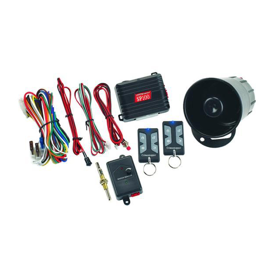
CONGRATULATIONS on your choice of a "Security Plus" Remote Alarm System by Crimestopper Security
Products Inc. This booklet contains the information necessary for installing, using, and maintaining your alarm
system. If any questions arise, contact your installation dealer or Crimestopper Security Products Inc. at the
Tech Support number below.
This installation book is designed for the installer or individual with an existing understanding of automotive
electrical systems, along with the ability to test and connect wires for proper operation. To ease installation,
we suggest that you READ THIS MANUAL before beginning your installation. This book is provided as a
GENERAL GUIDLINE and the information contained herein may differ from your vehicle.
TECH SUPPORT
Mon-Fri 8:00 AM-4:30 PM Pacific Time
www.crimestopper.com
Phone (800) 998-6880
FAX (805) 581-9500
REV. B 02.2009
SP-100
REMOTE CONTROL ALARM SYSTEM
INSTALLATION & OPERATING INSTRUCTIONS
INTRODUCTION
This device complies with FCC Rules part 15. Operation is subject to
the following two conditions: 1) This device may not cause interference,
and (2) this device must accept any interference that may be received,
including interference that may cause undesired operation.
manufacturer is not responsible for any radio or TV interference caused
by unauthorized modification to this equipment. Such modification
could void the user's authority to operate the equipment.
1
The
Advertisement
Table of Contents

Related Manuals for CrimeStopper SP-100


Summary of Contents for CrimeStopper SP-100
- Page 1 CONGRATULATIONS on your choice of a “Security Plus” Remote Alarm System by Crimestopper Security Products Inc. This booklet contains the information necessary for installing, using, and maintaining your alarm system. If any questions arise, contact your installation dealer or Crimestopper Security Products Inc. at the Tech Support number below.
-
Page 2: Table Of Contents
TABLE OF CONTENTS Installation Cautions & Warnings…….………………………………………………………….……….…….……2 Control Module & Component Mounting…………….………………………..…………………..….….…….…..3 Wiring……..……………………………………………………………………………………………………...…….4-5 Power Door Lock Wiring...…………………………………………………….………..………………….…………6 Transmitter Programming…………………………………………………………………………………….………7 Option Programming………………………………………….………………………………..………………….8-10 Operating Instructions………………………..……………………………………………………..……..…….11-13 Car Jack Protection…………………………………………………………….…………..…….……..……………14 LED / Valet Switch……………………………………………………………………….………………..…..………15 Shock Sensor……...…………………………………………………………………………..…………..…..………15 System Wiring Diagram……………………………………………………………………………………...………16 INSTALLATION CAUTIONS & WARNINGS BEFORE BEGINNING, check all vehicle manufacturer cautions and warnings regarding electrical service (AIR BAGS, ABS BRAKES, ENGINE COMPUTERS, BATTERY etc.). -
Page 3: Control Module & Component Mounting
CONTROL MODULE MOUNTING DO NOT Mount the control unit in the engine compartment! DO NOT Mount the control unit or wiring harness where they can become entangled with moving parts such as brake/gas/clutch pedals, or the steering column! The alarm control module should be mounted in a concealed location. The Placement of the module will affect the distance from which the remote transmitter can control the unit. -
Page 4: Wiring
WIRING GREEN WIRE: (-) DOOR TRIGGER Identify the wire that reads ground when any door is open and 12 volts when all doors are closed. Some vehicles may have isolated door triggers. In this case you may need to run additional wires from other doors or go directly to the wire that triggers the vehicle’s interior dome light. -
Page 5: Wiring
ORANGE WIRE: (-) NEGATIVE ARMED OUTPUT / STARTER DISABLE (500mA Ground, Optional) This wire becomes a (-) Ground Output when the System is Armed. This output is used for disabling the starter or to activate optional devices such as extra sensors, LED’s, window roll-up modules, voice modules etc. -
Page 6: Power Door Lock Wiring
GREEN WHITE: (-) Negative LOCK Pulse, BLUE WHITE: (-) Negative UNLOCK Pulse NEGATIVE TRIGGER DOORLOCK WIRING GREEN WHITE BLUE WHITE REVERSE POLARITY DOOR LOCK WIRING GREEN WHITE BLUE WHITE MASTER SWITCH POWER DOOR LOCK WIRING POSITIVE TRIGGER DOORLOCK WIRING GREEN WHITE BLUE WHITE FACTORY POWER... -
Page 7: Transmitter Programming
REMOTE TRANSMITTER PROGRAMMING 1. Turn Ignition ON. 2. Press the Program/Override Button 4 times. After a few second delay, the unit will chirp and flash the lights 4 times. 3. Press button 1 on the remote control you wish to learn. You should get 2 light flashes indicating the unit is waiting for a 2 code, then press button #1 of a second transmitter or transceiver, the unit will chirp and flash the lights 3 times indicating its waiting for the 3... -
Page 8: Option Programming
1. Turn the Ignition ON and press the Override/Program button 5 times. After a slight delay, the system will chirp and flash the lights 5 times. 2. Within the next few seconds, press the Override/Program button [again] the number of times that corresponds to the feature list below. - Page 9 OPTION PROGRAMMING NOTE: Options can be instantly restored to Factory Default Values. To restore default values: Perform step #1 above, then press button 3. The siren and horn will chirp 4 times and lights will flash 4 times. Turn OFF Ignition. All programming options will be restored to * Default * values, See Programming Chart.
- Page 10 OPTION PROGRAMMING Cont. 6. DOUBLE UNLOCK PULSE The unit will send 2 Unlock Pulses when the #2 Unlock button is pressed. This feature may be required for interfacing this alarm with an existing Factory Keyless Entry or Alarm system in a vehicle. These systems are found on some Nissan, VW, Toyota, and Lexus vehicles.
-
Page 11: Operating Instructions
ACTIVE ARMING To arm the alarm and lock the doors, press the #1 Button (Lock Symbol) on the transmitter. You will hear a single siren chirp and the lights will flash once. The system will arm, the doors will lock and the starter will be disabled if these optional features are installed. - Page 12 OPERATING INSTRUCTIONS Cont. ACTIVE RE-ARMING ( FAIL SAFE PROTECTION ) The Active Re-Arming feature allows the system will Re-Arm itself 40 seconds after being disarmed with the transmitter if a door has not yet been opened. This is handy if the vehicle is accidentally disarmed (via the transmitter in your pocket) without you knowing it.
- Page 13 OPERATING INSTRUCTIONS EMERGENCY OVERRIDE & DISARM If you have lost the transmitter or it stops working for any reason and the Alarm is armed, you will have to perform and Emergency Override to Disarm the Alarm. Open the door with the key, (alarm will sound). Turn the ignition on and press the override/program button 4-5 seconds (until siren stops).
-
Page 14: Carjack Protection
CARJACK PROTECTION ACTIVE CARJACK This feature provides Active Carjack protection and must be enabled before use through Alarm programming (option 10). See page 8. When the Ignition is on (running), press button #2 ( Unlock Symbol ). Parking lights will flash TWICE to confirm the Carjack countdown sequence. 90 Seconds later, the unit will begin a Carjack Cycle consisting of 20 seconds of pre-warning chirps turning into a full system activation with siren/flashing light pulses for 5 min. -
Page 15: Led / Valet Switch
LED / VALET SWITCH MOUNTING LED: The LED is used as a System Status Indicator and it will also FLASH for use as security deterrent when the Alarm System is Armed. VALET SWITCH: Mount the Valet Switch (push-button) on dash or other accessible location. It is REQUIRED for Emergency Disarm, Programming and entering Valet Mode (See pg 13 for Valet Mode). -
Page 16: System Wiring Diagram
(+) Siren Brown 15 AMP FUSE 12 Volt Battery (+) Parking Lights 7.5 AMP White FUSE (+) Parking Lights 7.5 AMP White FUSE WIRING DIAGRAM SP-100 Orange Black Ground STARTER SOLENOID Green/white Lock (500mA) DOOR LOCKS Blue/white Unlock (500mA) Horn Honk...