Advertisement
Quick Links
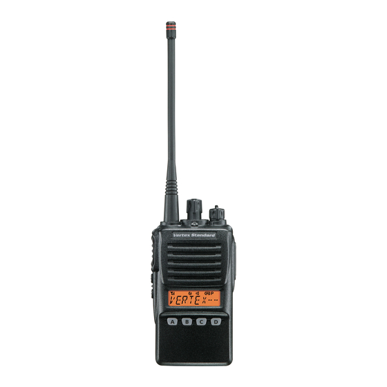
VX-350 Series
Operating Manual
Controls & Connectors
Controls & Connectors
Controls & Connectors
Controls & Connectors
Controls & Connectors
LED Indicator
Glows Green
Monitor on (or Side 1, or 2 switch is activated: Non-LCD version)
Blinking Green
Busy Channel (or SQL off)
Glows Red
Transmitting
Blinking Red
Battery Voltage is Low
Yellow
Receiving a Selective Call
CH ( Channel ) Selector
Antenna
VOL/PWR Knob
Speaker
MIC/SP Jack
Push To Talk
( External Mic/Earphone )
( PTT ) Switch
Side 1 Switch
Microphone
Side 2 Switch
LCD
(LCD V
)
4 Key
(LCD V
ERSION
ERSION
Battery Pack Latch
Accessories & Options
Accessories & Options
Accessories & Options
Accessories & Options
Accessories & Options
FNB-V95LI 7.4 V 1800 mAh Lithium-Ion Battery
FNB-V96LI 7.4 V 2000 mAh Lithium-Ion Battery
VAC-300
Desktop Rapid Charger
VAC-6300
6-unit Multi Charger
PA-42
AC Adapter (for VAC-300)
PA-41
AC Adapter (for VAC-6300)
MH-45
Speaker/Microphone
B4B
MH-360S
Speaker/Microphone
MH-450S
Speaker/Microphone
VC-25
VOX Headset
VCM-2
Vehicle Charger Mount Adapter (for VAC-300)
FVP-25
Encryption/DTMF pager Unit
FVP-35
Encryption Unit (Rolling code voice scrambler)
FVP-36
Encryption Unit
VME-100
MDC1200
®
/GE-Star
®
ANI Encoder Unit
ATU-6A
Rubber Antenna 400-430 MHz
ATU-6B
Rubber Antenna 420-450 MHz
ATU-6C
Rubber Antenna 440-470 MHz
ATU-6D
Rubber Antenna 450-485 MHz
ATU-6F
Rubber Antenna 485-520 MHz
ATV-6XL
Rubber Antenna 134-174 MHz (Untuned)
ATV-8A
Rubber Antenna 134-151 MHz
ATV-8B
Rubber Antenna 150-163 MHz
ATV-8C
Rubber Antenna 161-174 MHz
CLIP-18
Belt Clip
CE86
Programming Software
FIF-10A
USB Programming Interface
CT-106
PC Programming Cable (for FIF-10A)
E C 0 6 5 N 1 0 0
Before You Begin
Before You Begin
Before You Begin
Before You Begin
Before You Begin
B
P
I
R
ATTERY
ACK
NSTALLATION AND
EMOVAL
To install the battery, hold the transceiver with your left hand, so
your palm is over the speaker and your thumb
is on the top of the belt clip. Insert the
battery pack into the battery com-
partment on the back of the
radio while tilting the
Belt Clip outward,
then push the bottom
side of the battery
pack until the battery
pack locks with the
Battery Pack Latch.
To remove the battery, turn the radio off and remove any protective
cases. Slide the Battery Pack Latch on the bottom of the radio, then
slide the battery downward and out from the radio while holding
the Belt Clip.
Caution!
Do not attempt to open any of the rechargeable Lithium-Ion
packs, as they could explode if accidentally short-circuited.
L
B
I
OW
ATTERY
NDICATION
As the battery discharges during use, the voltage gradually becomes
)
lower. When the battery voltage becomes to low, substitute a freshly
charged battery and recharge the depleted pack. When the battery volt-
age is low, the TX/BUSY indicator on the top of the radio will blink
red and "Battery Indicator" on the LCD will blink on the LCD ver-
sion. Furthermore, if your Dealer sets the "Low Battery Alert" feature
into the transceiver, an alert beeper will sound when the battery volt-
age is low.
Display Icons & Indicators
Display Icons & Indicators
Display Icons & Indicators
Display Icons & Indicators
Display Icons & Indicators
: This channel is in the "Scan" List
: "Priority Scan" is activated
"Call" Indicator
"Dual Watch" is activated
Receiver Monitor
Low Power Transmit Mode
"Talk-Around" is enabled
"Encryption" is enabled
RSSI Indicator
8 Character Alpha-numeric Display
Important Notice for North American Users
Regarding 406 MHz Guard Band
The U.S. Coast Guard and National Oceanographic and Atmo-
spheric Administration have requested the cooperation of the
U.S. Federal Communications Commission in preserving the
integrity of the protected frequency range 406.0 to 406.1 MHz,
which is reserved for use by distress beacons. Do not attempt
to program this apparatus, under any circumstances, for opera-
tion in the frequency range 406.0 - 406.1 MHz if the apparatus
is to be used in or near North America.
Warning - Frequency band 406 - 406.1 MHz is reserved for use
ONLY as a distress beacon by the US Coast Guard and NOAA.
Under no circumstance should this frequency band be part of
the preprogrammed operating frequencies of this radio.
P
S
RELIMINARY
TEPS
Install a charged battery pack onto the transceiver, as described
previously.
Push the bottom side
Screw the supplied antenna onto the Antenna jack. Never attempt
of the battery pack
to operate this transceiver without an antenna connected.
If you have a Speaker/Microphone, we recommend that it not be
connected until you are familiar with the basic operation of the
VX-350.
O
Q
S
PERATION
UICK
TART
Turn the top panel's VOL/PWR knob
clockwise to turn on the radio on.
Turn the top panel's CH selector knob
to choose the desired operating channel.
Rotate the VOL/PWR knob to set the
volume level. If no signal is present,
press and hold in the Programmable
key assigned to "SQL OFF" for more
than one second; background noise will
now be heard, and you may use this to
set the VOL/PWR knob for the desired
audio level.
( LCD Version
LCD Version )
LCD Version
LCD Version
LCD Version
This Radio has been tested and complies with the Federal Communi-
cations Commission (FCC) RF exposure limits for Occupational Use/
Controlled exposure environment. In addition, it complies with the
following Standards and Guidelines:
FCC 96-326, Guidelines for Evaluating the Environmental Effects
of Radio-Frequency Radiation.
FCC OET Bulletin 65 Edition 97-01 (1997) Supplement C, Evalu-
Battery Indicator
ating Compliance with FCC Guidelines for Human Exposure to
Radio Frequency Electromagnetic Fields.
ANSI/IEEE C95.1-1992, IEEE Standard for Safety Levels with
Respect to Human Exposure to Radio Frequency Electromagnetic
Fields, 3kHz to 300 GHz.
ANSI/IEEE C95.3-1992, IEEE Recommended Practice for the
Measurement of Potentially Hazardous Electromagnetic Fields-
RF and Microwave.
Priority Channel indication
WARNING: This radio generates RF electromagnetic energy
during transmit mode. This radio is designed for and classified
as Occupational Use Only, meaning it must be used only during the
course of employment by individuals aware of the hazards, and the
ways to minimize such hazards. This radio is not intended for use by
the General Population in an uncontrolled environment.
CAUTION: To ensure that your expose to RF electromagnetic
energy is within the FCC allowable limits for occupational use,
always adhere to the following guidelines:
This radio is NOT approved for use by the general population
in an uncontrolled environment. This radio is restricted to oc-
cupational use, work related operations only where the radio
operator must have the knowledge to control its RF exposure
conditions.
When transmitting, hold the radio in a vertical position with
its microphone 1 to 2 inches (2.5 to 5 cm) away from your
mouth and keep the antenna at least 1 inch (2.5cm) away from
your head and body.
Operation
Operation
Operation
Operation
Operation
Press and hold in the Programmable
key assigned to "SQL OFF" for more
than one second (or press the key twice)
to quiet the noise and resume normal
(quiet) monitoring.
To transmit, monitor the channel and
make sure it is clear.
THIS IS AN FCC REQUIRMENT!
To transmit, press and hold in the PTT
switch. Speak into the microphone area
of the front panel grille (lower right-hand
corner) in a normal voice level. To re-
turn to the Receive mode, release the PTT switch.
If a Speaker/Microphone is available, remove the plastic cap and
its two mounting screws from the right side of the transceiver, then
insert the plug from the Speaker/Microphone into the MIC/SP jack;
secure the plug using the screws supplied with the Speaker/Micro-
phone. Hold the speaker grille up next to your ear while receiving.
To transmit, press the PTT switch on the Speaker/Microphone, just
as you would on the main transceiver's body.
Note:Save the original plastic cap and its mounting screws. They
should be re-installed when not using the Speaker/Micro-
phone.
SAFETY TRANING INFORMATION
SAFETY TRANING INFORMATION
SAFETY TRANING INFORMATION
SAFETY TRANING INFORMATION
SAFETY TRANING INFORMATION
The radio must be used with a maximum operating duty cycle
not exceeding 50 %, in typical Push-to-Talk (PTT) configura-
tions. DO NOT transmit for more than 50 % of total radio use
time (50 % duty cycle). Transmitting more than 50 % of the
time can cause FCC RF exposure compliance requirements to
be exceeded.
The radio is transmitting when the red LED on the top of the
radio is illuminated. You can cause the radio to transmit by
pressing the PTT button or by using the VOX headset, model
VC-25.
DO NOT transmit when the radio is used in Body Worn con-
figuration with the following accessory: belt-clip (CLIP-18).
It must be used ONLY for (1) there is a 4 cm distance from the
body during transmitting, (2) monitoring purposes, using the
speaker only and (3) for carrying purposes.
Always use Vertex Standard authorized accessories.
The information listed above provides the user with the information
needed to make him or her aware of RF exposure, and what to do to
assure that this radio operates with the FCC RF exposure limits of this
radio.
Electromagnetic Interference/Compatibility
During transmissions, this radio generates RF energy that can
possibly cause interference with other devices or systems. To avoid
such interference, turn off the radio in areas where signs are posted
to do so.
Do not operate the transmitter in areas that are sensitive to elec-
tromagnetic radiation such as hospitals, health care facilities, air-
craft, and blasting sites.
FCC LICENSE INFORMATION
This radio operates on communications frequencies which are sub-
ject to FCC (Federal Communications Commission) Rules and
Regulations. FCC Rules require that all operators using Private
Land Mobile radio frequencies obtain a radio license before op-
erating their equipment.
Advertisement

Related Manuals for Vertex Standard VX-354


Summary of Contents for Vertex Standard VX-354
- Page 1 It must be used ONLY for (1) there is a 4 cm distance from the body during transmitting, (2) monitoring purposes, using the speaker only and (3) for carrying purposes. Always use Vertex Standard authorized accessories. WARNING: This radio generates RF electromagnetic energy The information listed above provides the user with the information during transmit mode.
- Page 2 Press (or Press and hold) the assigned Programmable key momen- keys. These Programmable keys functions can be customized (set tarily to disable the Tone squelch. to other functions), via programming by your VERTEX STANDARD dealer, to meet your communications/network requirements. Some fea- Lamp...