Advertisement
Quick Links
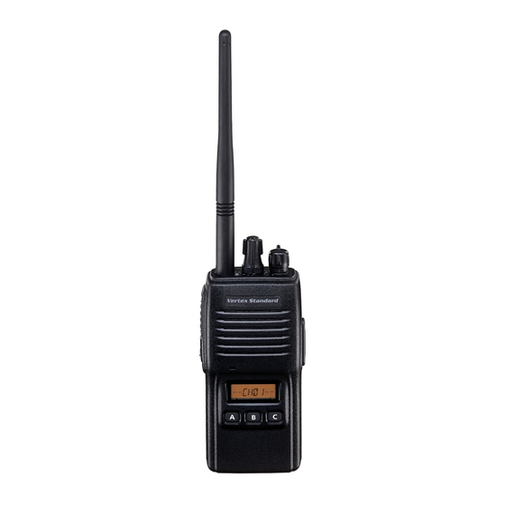
VX-160/-180
Operating Manual
Controls & Connectors
LED Indicator
Glows Green
Monitor on
Blinking Green Busy Channel (or SQL off)
Glows Red
Transmitting
Blinking Red
Battery Voltage is low
Blinking Yellow Receiving a Selective Call
CH ( Channel ) Selector
Antenna
VOL/PWR Knob
Push To Talk
( PTT ) Switch
MIC/SP Jack
( External Mic/Earphone )
Speaker
Monitor Button
LCD
(VX-180)
Microphone
Soft KEY
(VX-180)
Battery Pack Latch
0108m-GE
E C 0 1 3 N 7 5 2
Important Notice!
FCC RF Exposure Compliance Requirements for Occupational Use Only:
This Radio has been tested and complies with the Federal Communications Commission (FCC) RF exposure limits for Occupational Use/
Controlled exposure environment. In addition, it complies with the following Standards and Guidelines:
r FCC 96-326, Guidelines for Evaluating the Environmental Effects of Radio-Frequency Radiation.
r FCC OET Bulletin 65 Edition 97-01 (1997) Supplement C, Evaluating Compliance with FCC Guidelines for Human Exposure to Radio
Frequency Electromagnetic Fields.
r ANSI/IEEE C95.1-1992, IEEE Standard for Safety Levels with Respect to Human Exposure to Radio Frequency Electromagnetic
Fields, 3 kHz to 300 GHz.
r ANSI/IEEE C95.3-1992, IEEE Recommended Practice for the Measurement of Potentially Hazardous Electromagnetic Fields - RF and
Microwave.
m This radio is NOT approved for use by the general population in an uncontrolled environment. This radio is restricted to
occupational use, work related operations only where the radio operator must have the knowledge to control its RF exposure
conditions.
m When transmitting, hold the radio in a vertical position with its microphone 1 to 2 inches (2.5 to 5 cm) away from your mouth
and keep the antenna at least 1 inch (2.5 cm) away from your head and body.
m The radio must be used with a maximum operating duty cycle not exceeding 50%, in typical Push-to-Talk (PTT) configurations.
DO NOT transmit for more than 50% of total radio use time (50% duty cycle). Transmitting more than 50% of the time can
cause FCC RF exposure compliance requirements to be exceeded.
The radio is transmitting when the red LED on the top of the radio is illuminated. You can cause the radio to transmit by
pressing the PTT button.
m DO NOT transmit when the radio is used in Body Worn configuration with the following accessory: belt-clip (Parts # CP7064001).
It must be used ONLY for (1) there is a 4 cm distance from the body during transmitting, (2) monitoring purposes, using the
speaker only and (3) for carrying purposes.
m Always use Vertex Standard authorized accessories.
Notice !
There are no owner-serviceable parts inside the transceiver.
All service jobs must be referred to an authorized
Service Representative. Consult your Authorized
Dealer for installation of optional accessories.
Before You Begin
Battery Pack Installation and Removal
r To install the battery, hold the transceiver with your left hand, so
your palm is over the speaker and your thumb is on the top of the
belt clip. Insert the battery pack into the battery compartment on
the back of the radio while tilting the Belt Clip outward, then
close the Battery Pack Latch until it locks in place with a "Click."
r To remove the battery, turn the radio off and remove any protec-
tive cases. Open the Battery Pack latch on the bottom of the ra-
dio, then slide the battery downward and out from the radio while
holding the Belt Clip.
Caution!
Do not attempt to open any of the rechargeable Ni-Cd packs,
as they could explode if accidentally short-circuited.
Low Battery Indication
r As the battery discharges during use, the voltage gradually be-
comes lower. When the battery voltage reaches 6.3 volts, substi-
tute a freshly charged battery and recharge the depleted pack.
The TX/BUSY indicator on the top of the radio will blink red
(on the VX-180, the "
" icon will appear on the LCD) when
the battery voltage is low.
r Avoid recharging Ni-Cd batteries often with little use between
charges, as this can degrade the charge capacity. We recommend
that you carry an extra, fully-charged pack with you so the opera-
tional battery may be used until depletion (this "deep cycling"
technique promotes better long-term battery capacity).
This device complies with Part 15 of the FCC rules. Operation
is subject to the condition that this device does not cause harm-
ful interference.
Preliminary Steps
r Install a charged battery pack onto the transceiver, as described
previously.
r Screw the supplied antenna onto the Antenna jack. Never attempt
to operate this transceiver without an antenna connected.
r If you have a Speaker/Microphone, we recommend that it not be
connected until you are familiar with the basic operation of the
VX-160/-180.
Operation Quick Start
r Turn the top panel's VOL/PWR
knob clockwise to turn on the radio
on.
r Turn the top panel's CH selector knob
to choose the desired operating chan-
nel.
r Rotate the VOL/PWR knob to set the
volume level. If no signal is present,
press and hold in the MONITOR key
(the lower button on the left side) for
more than 1 seconds; background
noise will now be heard, and you may
use this to set the VOL/PWR knob
for the desired audio level.
Display Icons & Indicators
( VX-180 Only )
This indicator confirms that
D
W
is active.
UAL
ATCH
This icon is the "Low Battery" in-
This indicator confirms that
dicator, which appears when the
this channel will be skipped
battery voltage becomes too low
during scan.
for proper operation.
This indicator confirms that
8 Character Alpha-numeric
D
2-T
D
is active.
Invertible Display
UAL
ONE
ECODE
Accessories & Options
FNB-64
7.2 V 700 mAh Ni-Cd Battery
FNB-V57
7.2 V 1100 mAh Ni-Cd Battery
FBA-25
Alkaline Battery Case
NC-77B
120 VAC Overnight Desktop Charger
NC-77C
230-240 VAC Overnight Desktop Charger
VAC-800
Desktop Rapid Charger
VAC-6800
6-unit Multi Charger
MH-45
Speaker/Microphone
B4B
MH-37
Earpiece Microphone
A4B
VC-25
VOX Headset
VCM-1
Mobile Mounting Bracket (for VAC-800)
LCC-160/S Leather Case (for VX-160)
LCC-180/S Leather Case (for VX-180)
CT-42
PC Programming Cable
CT-27
Radio to Radio Programming Cable
CE44
Programming Software
Operation
r Press and hold in the MONITOR key
for more than 1 seconds (or press the
MONITOR key twice) to quiet the
noise and resume normal (quiet)
monitoring.
r To transmit, press and hold in the PTT
switch. Speak into the microphone
area of the front panel grille (lower
left-hand corner) in a normal voice
level. To return to the Receive mode,
release the PTT switch.
r If a Speaker/Microphone is available, remove the plastic cap and
its two mounting screws from the right side of the transceiver,
then insert the plug from the Speaker/Microphone into the MIC/
SP jack; secure the plug using the screws supplied with the
Speaker/Microphone. Hold the speaker grille up next to your ear
while receiving. To transmit, press the PTT switch on the Speaker/
Microphone, just as you would on the main transceiver's body.
Note:Save the original plastic cap and its mounting screws. They
should be re-installed when not using the Speaker/Micro-
phone.
Key Functions
The VX-180 provides programmable [ A ] , [ B ] , and [ C ] function keys,
and both the VX-160 and VX-180 provide programmable MONI-
TOR keys. These "Soft" keys functions can be customized (set to
other functions), via programming by your VERTEX STANDARD
dealer, to meet your communications/network requirements. Some
features may require the purchase and installation of optional inter-
nal accessories. The possible Soft key programming features are
illustrated below, and their functions are explained in the next chap-
ter. For further details, contact your VERTEX STANDARD dealer.
For future reference, check the box next to each function that has
been assigned to the Soft key on your particular radio, and keep it
handy.
Soft Key
Function
[A]
[B]
[C]
None
Monitor
Low Power
Lock*
Lamp*
Channel Up*
Channel Down*
Scan
Follow-me Scan
Dual Watch
Talk Around
Add/Del*
Call/Reset
Speed Dial
TX Save Off
* VX-180 only
MONITOR key
Advertisement

Related Manuals for Vertex Standard VX-160


Summary of Contents for Vertex Standard VX-160
-
Page 1: Important Notice
Key Functions The VX-180 provides programmable [ A ] , [ B ] , and [ C ] function keys, This indicator confirms that and both the VX-160 and VX-180 provide programmable MONI- is active. ATCH TOR keys. These “Soft” keys functions can be customized (set to... -
Page 2: Description Of Operating Functions
Under some circumstances, though, your hand-held radio may not be heard well at the other end of the com- munication path, and high power may be necessary at all times. VERTEX STANDARD CO., LTD. 4-8-8 Nakameguro, Meguro-Ku, Tokyo 153-8644, Japan VERTEX STANDARD US Headquarters 17210 Edwards Rd., Cerritos, CA 90703, U.S.A.