Table of Contents
Advertisement
PERATOR'S MANUAL
T
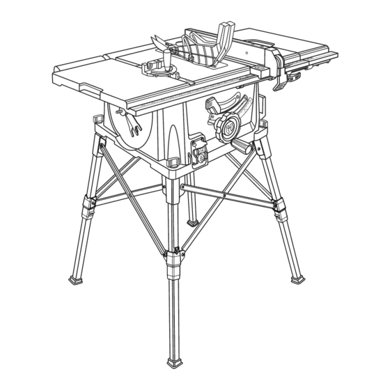
10 in. TABLE SAW
Model No.
315.284620
A
WARNING:
To reduce the risk of injury, the
user must read and understand the operator's
manual before using this product.
Customer
Help Line: 1-800-932-3188
Product
distributed
in the United
States
by Sears
Brands
Management
Corporation
Hoffman
Estates,
IL 601 79
Visit the Craftsman
web page: www.craftsman.com
987000-910
4-23-10 (REV:03)
Save this manual
for future
reference
Advertisement
Table of Contents

Related Manuals for Craftsman 315.28462


Summary of Contents for Craftsman 315.28462
- Page 1 Customer Help Line: 1-800-932-3188 Product distributed in the United Hoffman Estates, IL 601 79 Visit the Craftsman web page: www.craftsman.com 987000-910 Save this manual 4-23-10 (REV:03) States by Sears Brands Management for future...
- Page 2 [] Illustrated Parts List ... [] Parts Ordering/Service CRAFTSMAN ONE YEAR FULL WARRANTY FOR ONE YEAR from the date of purchase, this product is warranted against any defects in material or workmanship. Defective product will receive free repair or free replacement if repair is unavailable.
- Page 3 [] KEEP WORK AREA CLEAN. Cluttered areas and benches invite accidents. DO NOT leave tools or pieces of wood on the saw while it is in operation. [] DO NOT USE IN DANGEROUS Do not use power tools in damp or wet locations or expose to rain.
- Page 4 Never use blade washers or blade bolts that are defective or incorrect. The maxi- mum blade capacity of your saw is 10 in. (254 mm). [] BEFORE MAKING A CUT, BE SURE ALL ADJUST= MENTS ARE SECURE.
- Page 5 OFF and disconnecting from the power source. • PROVIDE ADEQUATE SUPPORT to the rear and sides of the saw table for wide or long workpieces. • AVOID KICKBACKS (work thrown back toward you) a) Keeping blade sharp.
-
Page 6: Symbols
Someofthefollowing symbols maybeusedonthistool•Please studythemandlearn theirmeaning• Proper i nter- pretation ofthesesymbols willallowyouto operate thetoolbetterandsafer• Safety Alert Read Operator's Manual Eye Protection No Hands Symbol Wet Conditions Alert Volts Amperes Hertz Watt Minutes Alternating Current Direct Current No Load Speed Class II Construction •../min Per Minute Indicates a potential personal injury hazard•... - Page 7 Thefollowing signal w ordsandmeanings a reintended to explain the levels of riskassociated w iththisproduct. SYMBOL SIGNAL DANGER: WARNING: CAUTION: CAUTION: SERVICE Servicing requires extreme care and knowledge and should be performed only by a qualified service tech- nician. For service we suggest you return the product to your nearest AUTHORIZED SERVICE CENTER for repair.
-
Page 8: Electrical
(DC). A substantial voltage drop will cause a loss of power and the motor will overheat. If the saw does not operate when plugged into an outlet, double check the power supply. SPEED... - Page 9 The distance that the tip of the saw blade tooth is bent (or set) outward from the face of the blade. Snipe (planers) Depression made at either end of a workpiece by cutter blades when the workpiece is not properly supported.
-
Page 10: Product Specifications
PRODUCTSPECIFICATIONS Blade Arbor... BladeDiameter ... Blade Tilt... Rating ... ANTI-KICKBACK RiViNG KNIFE PAWLS OUTFEED SUPPORT MITER GAUGE BLADE STORAGE BEVEL LOCKING LEVER 5/8 in. Input... 10in. NoLoadSpeed ... 0°- 45° CuttingDepth at0°... 120V,AConly, 6 0Hz CuttingDepth at45°... BLADE GUARD SPREADER/ HEIGHT/BEVEL ADJUSTING HANDWREEL... -
Page 11: Features
BLADE GUARD - Always keep the blade guard down over the saw blade for through-sawing BEVEL LOCKING LEVER - This lever, placed just under the saw table surface on the front of the cabinet, locks the angle setting of the blade. HEIGHT/BEVEL... -
Page 12: Operating Components
The blade guard assembly includes: riving knife/spreader/splitter, pawls, and plastic blade guard. POWER SWITCH This saw is equipped with a power switch that has a built-in locking feature. This feature is intended to prevent unauthorized and possible hazardous use by children and others. - Page 13 For maximum performance, it is recommended use the 36-tooth, 10 in. carbide-tipped provided with your saw. Additional blade styles of the same high quality are available for specific operations such as ripping. Your local dealer can provide you with complete information.
- Page 14 Thefollowing itemsareincluded withyourtablesaw: A. Anti-Kickback Pawls ... B. Blade Guard ... C. Miter Gauge ... D. Blade Wrench ... E. Handle Assembly ... R Rip Fence ... G. Push Stick ... H. Indicator ... I. Screw ... J. Leg Stand ... K.
-
Page 15: Loose Parts
UNPACKING This product requires assembly. [] Carefully lift saw from the carton and place it on a level work surface. NOTE: This tool is heavy. To avoid back injury, keep your knees bent and lift with your legs, not your back, and get help when needed. - Page 16 LEG STAN D See Figure 8. [] Place the table saw base on the leg stand. Position the locking knob over the holes in the top of the leg stand. [] Insert the screw on the locking knob into the hole and turn the locking knob clockwise to secure the table saw base to the leg stand.
-
Page 17: Operation
[] To reinstall the throat plate, slip the tab into the slot at the back of the saw and push down to secure in place. TO CHANGE BETWEEN... -
Page 18: Installation
See Figure 12. CAUTION: To work properly, the saw blade teeth must point down toward the front of the saw. Failure to do so could cause damage to the saw blade, the saw, or the workpiece. Unplug the saw. -
Page 19: Adjustments
See Figure 16. To check a(ignment of the spreader/riving [] Unplug the saw. [] Raise the saw blade by turning the height/bevel ing handwheel clockwise. [] Remove the anti-kickback pawls and blade guard assembly. Place a framing square or straight edge against both the saw blade and the spreader. - Page 20 [] Unlock the front and back table locking levers. [] Insert sliding table assembly into table locking levers. [] Push the table assembly until it rests against the saw table and is completely closed. [] Install phillips head screw into hole at end of the rear extension rod to hold sliding table assembly into lock- ing levers.
- Page 21 THE TABLE SAW ACCESSORIES See Figures 20 - 21. The table saw has two convenient storage areas (one on either side of the saw cabinet) specifically designed for the saw's accessories. When not in use, store the accessories securely by snap- ping each accessory in place.
-
Page 22: Basic Operation
[] Straight line cutting operations such as cross cutting, ripping, mitering, beveling, and compound cutting [] Dado with optional accessories [] Cabinet making and woodworking NOTE: This table saw is designed to cut wood and wood composition products only. BASIC... -
Page 23: Push Blocks
3 inches of the saw blade. They can be made in various sizes and shapes from scrap wood and used in a specific project. The stick must be narrower than the workpiece, with a 90 °... -
Page 24: Howto Makea Featherboard
Feed the stock only to the mark previ- ously made at 6 in. Turn the saw OFF and allow the blade to completely stop rotating before removing the stock. Reset the rip fence and cut spaced rips into the workpiece to allow approximately 1/4 in. -
Page 25: Typesof Cuts
[] Cut the wood with the finish side up. [] Knock out any loose knots with a hammer before making the cut. Always provide proper support for the wood as it comes out of the saw. © © cuts which can... - Page 26 THE BEVEL See Figure 30. If the bevel indicator is not at zero when the saw blade is at 90 ° , adjust the indicator by loosening the screw and setting it at 0 ° on the bevel scale. Retighten the screw.
- Page 27 TO USE THE RIP FENCE See Figure 31. [] Place the rear lip on the rear of the saw table and pull slightly toward the front of the unit. [] Lower the front end of the rip fence onto the guide surfaces on top of the front rail.
- Page 28 NOTE: After clamping the wood against the miter gage face, it must rest flat against both the saw table and miter gauge faces. MITER GAUGE REVERSED TO USE THE SLiDiNG See Figure 34.
- Page 29 [] Mark beside one of the blade teeth at the front of the blade. Place a combination square even with the front of the saw table and the side of the saw blade as shown in figure 36. Turn the blade so the marked tooth is at the back.
-
Page 30: Making Cuts
MAKING CUTS This table saw can perform a variety of cuts that are not all mentioned in this manual. DO NOT attempt to make any cuts not covered here unless you are thoroughly familiar with the proper procedures and necessary accessories. - Page 31 [] When the cut is made, turn the saw off. Wait for the blade to come to a complete stop before removing the workpiece.
-
Page 32: Makinga Bevelcrosscut
[] When the cut is made, turn the saw off. Wait for the blade to come to a complete stop before removing the workpiece. - Page 33 When the cut is made, turn the saw off. Wait for the blade to come to a complete stop before removing the workpiece.
-
Page 34: Makinga Large Panel Cut
[] Depending on the shape of the panel, use the rip fence or miter gauge. If the panel is too large to use either the rip fence or the miter gauge, it is too large for this saw. [] Make sure the wood does not touch the blade before you turn on the saw. -
Page 35: Makinga Dado Cut
The use of push blocks, push sticks, Fig. 48 and featherboards through cuts. [] When the cut is made, turn the saw off. Wait for the blade to come to a complete stop before removing the workpiece. Once aII dado cuts are completed: [] Unplug your saw. - Page 36 OFF position. Failure to heed this warning could result in serious personal injury. The table saw has been adjusted at the factory for mak- ing very accurate cuts. However, some of the components might have been jarred out of alignment during shipping.
- Page 37 TO SET THE BLADE AT 0 ° AND 45 ° See Figures 54 - 55. The angle settings of the saw have been set at the factory and, unless damaged in shipping, should not re- quire setting during assembly. After extensive use, they may need to be checked.
-
Page 38: Maintenance
TO CHECK THE ALIGNMENT FENCE TO THE BLADE See Figure 56. [] Unplug the saw. [] Raise the locking lever to permit the rip fence to be moved. [] Place a framing square beside the blade and move the rip fence up to the square. Take the dimension on the rip scale. -
Page 39: Accessories
Replace blade. Replace blade. Tighten all hardware. Reposition on flat surface. Adjust legs of optional stand. Check saw blade installation. Replace blade if necessary. Remount the rip fence. Clean and wax rails. Adjust clamp screw counterclockwise. Adjust clamp screw clockwise. - Page 40 PROBLEM Saw does not make accurate 90 ° or 45 ° cuts. Height/bevel adjusting hand- wheel is hard to turn. Saw does not start. Blade makes poor cuts. Blade does not lower when turning height/bevel adjusting handwheel. Motor labors in rip cut.
- Page 41 CRAFTSMAN 10 in. TABLE SAW - MODEL NUMBER 315.284620 See Figure l" FIGURE A...
- Page 42 CRAFTSMAN he model number will be found on a label attached to the cabinet. Always mention the model number in all correspondence 10 in. PORTABLE TABLE SAW or when ordering parts. PART NUMBER DESCRIPTION 089037008032 Screw (M6 x 65 mm) ...
- Page 43 ,.,. CRAFTSMAN 10 in. TABLE SAW - MODEL NUMBER 315.284620 See Figure See Figure FIGURE B...
- Page 44 CRAFTSMAN 10 he model number will be found on a label attached to the cabinet. Always mention the model number in all correspondence 10 in. PORTABLE TABLE SAW or when ordering parts. PART NUMBER DESCRIPTION 089110118707 Quick Stand (Leg Stand) ...
- Page 45 ,.,. CRAFTSMAN 10 in. TABLE SAW - MODEL NUMBER 315.284620 FIGURE C _k47...
- Page 46 ,.,, CRAFTSMAN 10 The model number will be found on a label attached to the cabinet. Always mention the model number in all correspondence 10 in. PORTABLE TABLE SAW or when ordering parts. PART NUMBER DESCRIPTION 089110118006 Saw Table ...
- Page 47 ,.,. CRAFTSMAN 10 in. TABLE SAW - MODEL NUMBER 315.284620 See Note On Page 48 FIGURE D...
- Page 48 CRAFTSMAN The model number will be found on a label attached to the cabinet. Always mention the model number in all correspondence 10 in. PORTABLE TABLE SAW or when ordering parts. PART NUMBER DESCRiPTiON 089037008096 Screw (M6 x 16 mm) ...
- Page 49 CRAFTSMAN 10 in. TABLE SAW - MODEL all correspondence regarding your TABLE SAW or when ordering repair parts. 1211 FIGURE E PART NUMBER 089110118011 089110118012 089037008183 089037008184 089037008185 089110118013 089037008187 089037008188 089037008189 089037008190 089037008191 089037008192 NUMBER PARTS LIST FOR FIGURE E DESCRIPTION Leg "A".
- Page 50 CRAFTSMAN The model number will be found on a label attached to the cabinet. Always mention the model number in / all correspondence regarding your TABLE SAW or when ordering repair parts. FIGURE F PART NUMBER 089037008033 089037008124 089037008119 089037008000...
-
Page 52: Troubleshooting
For expert troubleshooting @anag@ For repair - in your home - of all major brand appliances, lawn and garden equipment, no matter who made it, no matter who sold it! For the replacement owner's manuals that you need to do-it-yourself. For Sears professional and items like garage door openers and water heaters.