Table of Contents
Advertisement
Quick Links
Owner's Manual
I
PR
OFESS
IONAL
I
i
10 in. Stationary
RADIAL ARM SAW
Model No.
315.220381
Save this manual for
future reference.
CAUTION:
Read and follow all
Safety Rules and Operating
Instructions before first use of this
product.
Customer Help Line: 1-800-932-3188
Sears,
Roebuck
and Co.,
Hoffman
Estates,lL
60179
USA
Visit the Craftsman
web page: www.sears.com/craftsman
972000-705
10-99
• Safety
• Features
• Assembly
• Operation
• Maintenance
• Parts List
®
Advertisement
Table of Contents

Related Manuals for Craftsman 315.220381


Summary of Contents for Craftsman 315.220381
- Page 1 Read and follow all Safety Rules and Operating Instructions before first use of this product. Customer Help Line: 1-800-932-3188 Sears, Roebuck and Co., Hoffman Visit the Craftsman web page: www.sears.com/craftsman 972000-705 10-99 • Safety • Features • Assembly • Operation • Maintenance •...
-
Page 2: Table Of Contents
Carefully read through this entire owner's manual before using your new saw. Pay close attention to the Rules For Safe Operation, and all Safety Alert Symbols, includingDanger, Warning and Caution. If you use your saw properly and only for what it is intended, you will enjoy years of safe, reliable service. -
Page 3: Table Of Contents
Paralleling Blade to Table ... Aligning the Rip Scale Indicators... InstallingControl Cut Device ... • Operation ... Basic Operation of the Radial Arm Saw ... Types of Cuts ... Switch and Switch Key... Causes of Kickback ... Avoiding Kickback... Cutting Aids ... - Page 4 M KEEP WORK AREA CLEAN. Cluttered work areas and work benches invite accidents. DO NOT leave tools or pieces of wood on the saw while it is in operation. Keep floors clean and free of saw- dust.
-
Page 5: Electrical
REMOUNTING THE MOTOR; unplug the saw and remove the switch key. WARNING: When servicing, use only identical Craftsman replacement pads. Use of any other parts may create a hazard or damage product. • NEVER USE THIS TOOL IN AN EXPLOSIVE ATMOSPHERE. - Page 6 • USE A SUPPORT FOR THE SIDES AND BACK OF THE SAW TABLE when sawing wide or long workpieces to minimize the risk of blade pinching and kickback. Use a sturdy "outrigger"support to prevent tipping if a table extension more than 24 inches long is attached to the saw.
- Page 7 • SECURE THE SAW. Firmly belt the saw to the leg stand to keep the saw from tipping,walking, or sliding. • DO NOT SET UP WORK WITH THE BLADE SPINNING. Keep the saw power off until you are ready to use it.
- Page 8 ELECTRICAL CONNECTION Your Sears Craftsman Radial Arm Saw is powered by a precision built electric motor. It should be connected to a power supply that is 120 volta, 60 Hz, AC only (normal household current). It should be connected to a 240 volt power supply only if it has been reset according to the Instructions in this manual.
- Page 9 CHANGING VOLTAGE See Figures 2-4. Your radial saw has been set up at the factory to operate efficiently on a 120V AC single voltage circuit. However, if heavy duty operation is required, the circuits are overloaded, or the circuit is low voltage, have a qualified electrician change the voltage on the main power system to a 240V AC voltage circuit.
- Page 10 A type of rip cut in which the motor is between the blade and the column• (The blade is "outside" the motor). Puahatick A device used to feed the workpiece through the saw blade duringcutting operations. It helps keep the operator's hands well away from the blade. Rabbet A type of cut that gives a notch in the edge of a workpiece.
- Page 11 Resin A sticky, sap-based substance. Rip Cut In a radial saw, a cut made with the blade parallel to the fence and perpendicular to the arm. Can be across or with the grain. The teeth point up at the point of contact with the wood.
- Page 12 Check all loose parts from the box with the list below. Use the instructionson the followingpages to assemble. All fasteners are shown actual size. Saw Assembly ... Elevating Handwheel A. Handwheel ... :... _ ... :... 1 B. Screw (10-24 x 5/8 in. Soc. Hd.) ... 1 C.
- Page 13 Use the instructionson the followingpages to assemble. All fasteners are shown actual size. Saw Base To Leg Stand Assembly A. Saw Assembly (not shown) ... 1 B. Leg Stand Assembly (not shown) ... 1 C. Hex bolt (5/16-18 x 518 in. Hex Head) ... 4 D.
- Page 14 Check all loose parts from the box with the list below. Use the instructions on the following pages to assemble. All fasteners are shown actual size. 12. Table Support A. Table Support Rails ... 2 B. Square,head bolt (5/16-18 x 3/4 in.) ... 4 C.
- Page 15 The following tools are needed for assembly and alignment. They are not includedwith this saw. io@C LEVEL HEXKEYS: MEDIUM FLATBLADE SCREWDRIVER 5/32in.ANDI/8 in. #2 PHILLIPS SCREWDRIVER PENCIL SMALL HAMMER PLIERS WRENC S 7/161n,1/21n,9/161n_15/161n FRAMING SQUARE Fig. 7 rEAFTSMRIr RADIAL S AW 315.220381...
- Page 16 A WARNING / ADVERTENCIA • For your own safety, Read and understand /_1_ i I owner's manual before operating saw. * This tool has more than one connection to the power soorce. . To reduce the risk of electrical shock or injury, disconnect al| power connections •...
- Page 17 |eRinos. • Unplugsaw beforechangingthe blade or servicing, • Parssuseguridad, lea y entlende el manual d el preplutarlo a ntesde opersr la sierra LOCKED UNLOCKED rltllFI3NIIlr RADIAL S AW 315.220381 On I OffO ADVERTENCIA remrel b elore q ereUng Fig, 8B...
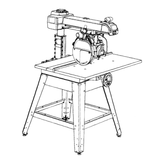
- Page 18 METHOD OF OPERATION: The column at the back of the saw supports the radial arm. The arm can be raised or lowered to change the blade height or swiveled left and right for a miter cut. A yoke fits into a carriage on the arm, which can travel back and forward.
- Page 19 Figures 9A and 9D. BLADE GUARD CLAMP SCREW - Secures the blade guard to the motor. Located between the blade andthe motor. See Figure 9D. MITERSCALE YOKEPIVOT LATCH MOTOR SCALE(S) COLUMN TUBE YOKE LOCKHANDLE COLUMNSUPPORT Fig. gB (IIRFTSMRN" RADIAL S AW 315.220381...
- Page 20 Located on the left side of the arm on the carriage cover. See Figure 9C. COLUMN - Upright housing at the beck of the saw, consisting of a column support and a column tube.
- Page 21 MOTOR (13/6.5 AMP) - Powers t heblade controlled by the switch and key at the front of the arm. The powerful induction motor has a capacitor start. It is mounted in the yoke and rotated with the bevel index knob and bevel lock lever. See Figure 9B. RIP SCALES - Show the distance from the fence to the blade.
-
Page 22: Loose Parts List
Assembly is best done in the area where the saw will be used. When you remove the saw and hardware from the packing materials, carefully check the items with the Loose Parts list. If you are unsure about the descriptionof any part, refer to their illustrations.For your convenience, all fasteners have been drawn actual size. - Page 23 4 hex nuts (5/16-18) • Place the saw on top of the leg stand so the holes in the saw base line up with the holes on top of the leg stand braces. • Put a washer on a screw, and put the screw and washer into the hole in the saw base.
- Page 24 Iockwasher. Do not dsk sedous injury or damage to the saw by failing to replace these parts. • Tighten the carriage lock knob, on the carriage cover on the left of the arm, to lock the yoke assembly in place.
- Page 25 Finger tighten or snug with a 112in. wrench only at this time. Final adjustments will be made later in Leveling The Table Supports section. TABLE SUPPORT BLADE INNERBLADE WASHER MOUNT TABLESUPPORTS Fig, 14 USINGTHESE HOLELOCATIONS SUPPORTS FLAT SQUARE WASHER HEADBOLT TABLE SUPPORT Fig. 15 rRBFTSMIIB °RADIAL S AW 315.220381...
- Page 26 • Swivel the motor slightly. It shouldbe at an angle in between one of the preset positive stop angles. tlIAFI_MRIr RADIAL S AW 315.220381 ARMCAP • Lock the yoke lock handle. Grasp the motorwith both hands and apply reasonable pressure to see if it slips.
- Page 27 SETTING THE BEVEL LOCK See Figures 18A -18C. The bevel lock lever locks the blade at desired angles other than the preset positive stop angles. The bevel lock lever is preset at the factory but may need readjustment after shippingor extended use. Check for overUghtnessor looseness and make any neces- sary adjustments as follows: The bevel lock lever is located on the front of the yoke...
- Page 28 TIGHTENING ARM AND See Figure 19. There should be no play, vertical or horizontal, in the arm relative to the column. If you can move the arm up, down or sideways when )he arm lock is unlocked, use the followingsteps to tighten the arm. Note: The arm should pivot only when the arm lock knob is unlocked and pulled forward to com- press the spring.
- Page 29 • Recheck the rotationby holdingthe front of the arm, grasping the top of the column supportwith the other, and pressingthe arm to the side, Rotation Adjustment SCREWS aRIRSMIU£RADIAL S AW 315.220381 COLUMN BLACK SCREWS Fig. 20C hex key, Fig. 20D...
- Page 30 Loose carriage bearings permit the blade to wander slightly while cutting, which will result in a poor cut and more wear and tear on the saw. Use the following steps to check for tightness and to then adjust the bearings if needed.
- Page 31 Move the arm to the opposite side and repeat the above procedure. When the opposite side is level, recheck the first side to make sure that it is still accurate and even. • Return the saw and motor to normal height and position. BLADE WRENCH AT FRONT [RRF1_NRrRADIALSAW315.220381...
- Page 32 • Snap the U-clip onto the front edge of the saw base. Line up the hole in the U-clip with the saw base hole just to the left of the center notch in saw base. See Figure 23B. • Place the table, top up, on the table supportsso the center counterbored hole lines up over the hole in the U-clip.
- Page 33 LEVELING FRONT TABLE See Figure 24. If there are any high or low areas on the front table, they should be removed by adjusting the leveling screws in the center holes on the front table. • Place the rear table on its edge across the front table to check for gaps.
- Page 34 See Figures 26,4 - 26C. • Collect the blade and hardware that were removed earlier. Place the inner blade washer, saw blade, outer blade washer, and blade nut on the blade arbor. See Figure 26,4. Note: The concave side of blade washers go against the blade.
- Page 35 Correct the dving knife position and retightenthe cap nut. CARRIAGE RIVING RIVING KNIFE CORRECT ALIGNMENT OFTHERIVINGKNIFE ANDANTI-KICK PAWLS Fig. 27A RIVINGKNIFE ONTOPOFFENCE TOOFARLEFTOFBLADE Fig. 27B YOKE LOCK :HANDLE FRONT TABLE FENCE Fig. 27C CRAFTSMAN" RADIAL SAW 315.220381...
- Page 36 The control cut device offers many benefits. As it increases operator control, it eliminates the risk in a cross cut of the saw "climbing" out and over the workpiece at the operator. Feed control of the blade as it cuts through the workplace increases, as does the accuracy of the cut.
- Page 37 Set the miter indicator on top of the column to O" • Replace the fence, spacer table, rear table, and table clamps. REARCOVER REMOVED FOR CLARITY Fig. 29A LOCKKNOB LOCK H_O_ Fig. 29B CRIIFTZNIIr SETSCREWS Fig. 29C RADIAL S AW 315.220381...
- Page 38 Place the square flat against the blade between two teeth. • If boththe top and bottom of the saw blade aN flat against the square, no adjustment is needed. • If the saw blade gaps at the top or bottom, remove the bevel index cap by removing the two phillips head screws (below the handle).
- Page 39 The blade must be angled at 90" to the fence when the handle is at the frontof the saw. If not, kickback could result during a cross cut. Kickback can cause serious injuryby throw- ing the workpiece toward the operator. In addi-...
- Page 40 PARALLELING BLADE TO TABLE See Figures 32A-32C. This procedure squares the blade to the table at 90" bevel so horizontal cuts will be accurate. This also reduces kickback, as well as splintering and burning of the cut edges of the workpiece. If the blade is not at 90"...
- Page 41 ALIGNING RIP SCALE INDICATORS See Figures 33A - 33B. The rip scale indicators on the arm show the distance between the blade and the rip fence. The upper scale is used when the fence is positioneddirectly behind the front table. The lower scale is used when the fence is at the extreme rear, directly in front of the column.
-
Page 42: Labels
The control cut device offers many benefits.As it Increases operator control,It eliminatesthe risk in a cross cut of the saw "climbing" out and over the workplace at the operator. Feed control of the blade as it cuts throughthe workpiece increases,as does the accuracy of the cut. - Page 43 It can make dado or molding cuts with special attachments. This saw is designed to cut wood and wood composi- tion products only. The three-prong plug must be plugged into a match- ing outlet that is properly installed and grounded according to all local codes and ordinances.
- Page 44 The yellow switch key prevents accidental starting of the main power switch when saw is not being used. To activate the switch, insert the switch key and lift switch to ON position. To lock the switch once it has been pressed to OFF, remove the yellow key.
- Page 45 Use a pushblcck when the blade is between 1/2 in. and 2 in. from the fence. (If the cut is narrower than 1/2 in., use a different saw.) Refer to the drawings and instructionsprovided so you can make safer and more precise cuts.
- Page 46 CARNAGE LOCKKNOB TABLECLAMPS €IIRFt'J;MIIIr RADIAL S AW 315.220381 • If the blade is angled, raise the plasticlower guard, release the bevel lock lever, and set the bevel indicatorto zero. RaUghtenthe bevel lock lever.
- Page 47 • Release the switch trigger and let the carriage return to the back. Turn the saw off with the switch on the arm but hold the handle until the blade stops rotating. Adjust the height with the elevating handwheel so the blade will rotate freely in the kerf.
- Page 48 [IIIFI"SNIIN" RADIAL SAW315.220381 • Release the switch triggerand let the carriage return to the back. Turn the saw off with the switch on the arm but hold the handle until the blade stops rotating.Adjust the height with the elevating handwheel so the blade will rotate freely in the ked.
- Page 49 • Release the switch tdgger and let the carriage return to the beck. Turn the saw off with the switch on the arm but hold the handle until the blade stops rotating.Adjust the height with the elevating handwheel so the blade will rotate freely in the kerr.
- Page 50 Push the workpiece past the pawls with push- blocksand pushsticks to finish the cut. • If the blade jams, turn the saw off with the switch on the arm, remove the yellow key, and wait for the blade to fullystop before freeing it.
- Page 51 • Cut a kerr. Turn the saw on with the switch on the arm. Lower the blade about 1/16 in. into the table to cut a shallow groove. Turn the saw off and remove the yellow key.
- Page 52 • Make sure the wood does not touch the blade before you turn on the saw with the switch on the arm. Let the blade build up to full speed before it contactsthe wood.
- Page 53 • Remove the blade and blade guard (see Assembly section). • Place a support the same height as the saw table nearby for the cut work. Lower the blade with the elevating handwheel. • Make sure the wood is not touching the blade.
- Page 54 GENERAL MAINTENANCE WARNING: When servicing, use only identical Craftsman replacement parts. Use of any other part may create a hazard or cause product damage. WARNING: To prevent accidental starting that could cause possible serious personal injury,turn off the saw with the switch on the arm, remove the switch key, and unplug the saw before working on the radial saw.
- Page 55 PROBLEM Saw does not start. Motor does not reach full speed or power. Motor stalls, blows fuses, or trips cimuit breakers. Motor overheats. CAUSE 1, Motor cord or control-cutcord is not plugged in, 2. Cord or switch is damaged. 3. Circuit fuse is blown.
- Page 56 Saw stalls when dpping. rlAFTSHAN"RADIALSAW315.220381 CAUSE I. Blade is warped, 2. Saw is not mounted securely. 3. Work surface is uneven. 1. Motor needs attention. 1, Track is dirtyor sticky. 2. Carriage beadngs are bad. 3. Blade or teeth are dull or bent.
-
Page 57: Setting The Yoke Clamp
PROBLEM Handwheel is hard to turn or column binds, Saw burns or scores edges of wood in cut. Bevel cuts are not true. CAUSE 1. Sawdust has collected on the elevating shaft, 2. Column is out of alignment. 1, Column tube is too loose in the column support. -
Page 58: Adjustments
PROBLEM Miter or cross cuts are not true. Wood edges away from fence when ripping. Depth of cut varies from one end of wood to the other. Riving knife strikes wood during a cut. CUKsNAr RADIALSAW315.220381 CAUSE 1. Scale pointer is not correct. 2. - Page 59 PROBLEM Saw blade tends to push wood to one side when cross cutting. CAUSE 1. Blade is heeling. 2. Column tube is loose in column support. 3. Arm is loose or misaligned. 4. Fence/tables are not straight. 5. Blade or teeth are bent or dull.
- Page 60 Always mention the model number in all correspondence regarding your RADIAL 19 13 SEERGURE E RGURE A RADIAL ARM SAW- MODEL NO. 315.220381 SEEFIGURE I "35 SEEFIGURES FANDG...
- Page 61 CRAFTSMANRADIAL ARM SAW- MODEL NO. 315.220381 I The model number willbe found on a plate attached to the base. Always mention the model number in all correspondence regardingyour RADIAL _ARM SAW or when ordering repair parts. PART NUMBER DESCRIPTION 976830-001 LowerArm Cover ...
- Page 62 CRAFTSMAN RADIAL ARM SAW - MODEL NO. 315.220381 in all correspondence regarding your RADIAL ARM SAW or when ordering repair parts. The model number will be found on a plate attached to the base, Always mention the model number SEE FIGt FIGUREB CRAFTSMRN"RADIALSAW315.220381...
- Page 63 CRAFTSMAN RADIAL in all correspondence regarding your RADIAL ARM SAW or when ordering repair parts. he model number will be found on a plate attached to the base. Always mention the model number PARTS LIST FOR FIGURE B PART NUMBER...
- Page 64 :::- CRAFTSMAN RADIAL ARM SAW - MODEL NO,, 315.220381 j_Them_de.numberw_i_bef_und_nap.atea_a_chedt_theba_A_waysmen_i_n_e_num_rin_c_rr_nde_r_rd._rR_AL .| ARM SAW or whe,.n orderingrepair pa_ts. .' ..'.'.'.- ::::: :::: FIGUREC i iiiii iiiii i:,:::-; : : :: : :: ... - ::: :...
- Page 65 Front/Rear Brace ... 976361-000 Complete Leg Stand Assembly (Includes Items ListedAbove) RADIAL ARM SAW - MODEL NO. 315.220381 PARTS LIST FOR FIGURE C * Standard Hardware Item -- May Be Purchased Locally ** Available From Div. 98 -- Source 980.00...
- Page 66 CRAFTSMAN RADIAL ARM SAW - MODEL NO. 315.220381 The model number will be found on a plate attached to the base. Always mention the model number in all correspondence regarding your RADIAL ARM SAW or when ordering repair parts. qp...- 8 FIGURED ClUlFTSMAN"TABLESAW315.220381...
- Page 67 CRAFTSMAN RADIAL ARM SAW - MODEL NO. 315.220381 The model number will be found on a plate attached to the base. Always mention the model number in all correspondence regarding your RADIAL ARM SAW or when ordering repair parts. PARTS LIST FOR FIGURE D...
- Page 68 CRAFTSMAN RADIAL ARM SAW - MODEL NO. 315.220381 in all correspondence regarding your RADIAL ARM SAW or when ordering repair parts. The model number willbe found on a plate attached to the base. Always mention the model number FIGUREE rltRFlrSMRN" TABLESAW315.220381...
- Page 69 CRAFTSMAN RADIAL ARM SAW- in all correspondence regarding your RADIAL ARM SAW or when ordering repair parts. The model number will be found on a plate attached to the base. Always mention the modelnumber PARTS LIST FOR FIGURE E PART...
- Page 70 CRAFTSMAN in all correspondence regarding your RADIAL ARM SAW or when ordering repair pads. The model number willbe foundon a plate attached to the base. Always mention the model number FIGUREF CRRFTSMRN"TABLESAW315.220381 RADIAL ARM SAW- MODEL NO. 315.220381 SEE FIGURE G...
- Page 71 CRAFTSMAN RADIAL ARM SAW - MODEL NO. 315.220381 in all correspondence regarding your RADIAL ARM SAW or when ordering repair parts, The model number will be found on a plate attached to the base. Always mention the model number PARTS LIST FOR FIGURE F...
- Page 72 CRAFTSMAN in all correspondence regarding your RADIAL ARM SAW or when ordering repair parts. The model number will be found on a plate attached tothe base. Always mentionthe model number SEE FIGURE F FIGUREG CRAFTSMAN" TABLE SAW 315,220381 RADIAL ARM SAW - MODEL NO. 315.220381...
- Page 73 CRAFTSMAN RADIAL in all correspondence regarding your RADIAL ARM SAW or when ordering repair parts. The model number willbe found on a plate attached to the base. Always mention the model number PARTS LIST FOR FIGURE G PART NUMBER DESCRIPTION 976773-001 Blade Nut ...
- Page 74 CRAFTSMAN RADIAL ARM SAW- MODEL NO. 315.220381 ARM SAW or when ordering repair parts. I The model number will be found on a plate attached to the base. Always mention the model number in all correspondence regarding your RADIAL /°...
- Page 75 * Screw (8-32 x 3/8 in. Pan Hd.) ... ** STD510803 •_ RADIAL ARM SAW- MODEL NO. 315.220381 PARTS LIST FOR FIGURE H * Standard Hardware Item -- May Be Purchased Locally •* Available From Div. 98 -- Source 980.00...
- Page 76 ARM SAW or when ordering repair parts. I The model number will be found on a plate attached to the base. Always mention the model number in all correspondence regardingyour RADIAL ",4 FIGUREI RADIAL ARM SAW - MODEL NO. 315.220381...
- Page 77 CRAFTSMANRADIAL ARM SAW - MODEL NO. 315.220381 ARM SAW or when ordering repair parts. The model number will be found on a plate attached to the base. Always mention the model number in all correspondence regarding your RADIAL PART NUMBER DESCRIPTION Guard Screw (10-24 Slotted) ...
- Page 78 ARM SAW or when ordering repair parts. The model number will be found on a plate attached to the base. Always mention the model number in all correspondence regarding your RADIAL SEEFIGUREK < FIGUREJ RADIAL ARM SAW - MODEL NO. 315.220381...
- Page 79 CRAFTSMANRADIAL ARM SAW- MODEL NO. 315,220381 ARM SAW or when ordering repair parts. I The model number will be found on a plate attached to the base. Always mention the model number in all correspondence regarding your RADIAL PART NUMBER...
- Page 80 CRAFTSMAN ARM SAW or when ordering repair parts. The model number will be found on a plate attached to the base. Always mention the model number in all correspondence regardingyour RADIAL FIGUREK RADIAL ARM SAW- MODEL NO. 315.220381...
- Page 81 NUMBER ** STD510803 * Screw (8-32 x 3/8 in. Pan Hd.) ... 662028-001 976420-001 976421o001 CRAFTSMAN RADIAL ARM SAW - MODEL NO. 315.220381 PARTS LIST FOR FIGURE DESCRIP_ON Pulley Flange ... Cable Assembly ... Clutch Assembly... * Standard Hardware Item -- May Be Purchased Locally ** Available From Div.
-
Page 82: Maintenance
In U.S.A. or Canada for in-home major brand repair service: Call 24 hours a day, 7 days a week 1-800-4-MY-HOME " (1-800-469-4663) Para pedir servicio de reparacibn a domicilio - 1-800-676-5811 Au Canada pour tout le service ou les pieces - 1-800-469 4663 For the repair or replacement parts you need: Call 6 a.m.