Table of Contents
Advertisement
Advertisement
Table of Contents

Related Manuals for Asus Maximus V Formula


Summary of Contents for Asus Maximus V Formula
- Page 1 MAXIMUS V FORMULA Series...
- Page 2 Product warranty or service will not be extended if: (1) the product is repaired, modified or altered, unless such repair, modification of alteration is authorized in writing by ASUS; or (2) the serial number of the product is defaced or missing.
-
Page 3: Table Of Contents
Contents Safety information ... vii About this guide ... viii MAXIMUS V FORMULA Series specifications summary ... x ROG ThunderFX specifications summary ... xv Package contents ... xvi Installation tools and components ... xvii Chapter 1: Product introduction Special features... 1-1 1.1.1... - Page 4 USB Configuration ... 3-28 Onboard Devices Configuration ... 3-30 APM ... 3-32 Network Stack ... 3-33 ASUS EZ Flash 2 Utility ... 3-39 ASUS O.C. Profile ... 3-39 ASUS SPD Information ... 3-40 GO Button File ... 3-41 ASUS Update ... 3-43 ASUS EZ Flash 2 ...
- Page 5 Ai Charger+ ... 4-17 4.3.8 USB Charger+ ... 4-18 4.3.9 Probe II... 4-20 4.3.10 Sensor Recorder ... 4-21 4.3.11 ASUS Update ... 4-23 4.3.12 MyLogo2 ... 4-24 4.3.13 Audio configurations... 4-25 4.3.14 ROG Connect... 4-28 4.3.15 GameFirst II ... 4-30 4.3.16...
- Page 6 Driver Installation ... 8-11 ThunderFX Utility Introduction ... 8-12 Appendices Notices ... A-1 ASUS contact information ... A-5 Installing two CrossFireX™ graphics cards ... 6-2 Installing three CrossFireX™ graphics cards ... 6-3 Installing the device drivers ... 6-4 Enabling the AMD CrossFireX™...
-
Page 7: Safety Information
Safety information Electrical safety • To prevent electrical shock hazard, disconnect the power cable from the electrical outlet before relocating the system. • When adding or removing devices to or from the system, ensure that the power cables for the devices are unplugged before the signal cables are connected. If possible, disconnect all power cables from the existing system before you add a device. -
Page 8: About This Guide
Refer to the following sources for additional information and for product and software updates. ASUS websites The ASUS website provides updated information on ASUS hardware and software products. Refer to the ASUS contact information. Optional documentation Your product package may include optional documentation, such as warranty flyers, that may have been added by your dealer. -
Page 9: Conventions Used In This Guide
Conventions used in this guide To ensure that you perform certain tasks properly, take note of the following symbols used throughout this manual. DANGER/WARNING: Information to prevent injury to yourself when trying to complete a task. CAUTION: Information to prevent damage to the components when trying to complete a task IMPORTANT: Instructions that you MUST follow to complete a task. -
Page 10: Maximus V Formula Series Specifications Summary
* The Intel Turbo Boost Technology 2.0 support depends on the CPU ® types. ** Refer to www.asus.com for Intel CPU support list Intel Z77 Express Chipset ® 4 x DIMM, max. 32GB, DDR3 2800 (O.C.)* / 2600 (O.C.)* / 2400 (O.C.)* / 2200(O.C.) / 2133(O.C.) / 1866(O.C.) / 1600 / 1333 /... -
Page 11: Audio Features
MAXIMUS V FORMULA Series specifications summary Storage Wireless Data Network Bluetooth ROG SupremeFX HD Audio Intel Z77 Express Chipset with RAID 0, 1, 5, 10 support ® - 2 x SATA 6.0 Gb/s ports (red) - 2 x SATA 3.0 Gb/s ports (black) - 1 x eSATA 3.0 Gb/s ports... - Page 12 - ASUS EZ Flash 2 - ASUS C.P.R. (CPU Parameter Recall) ASUS Q-Design - ASUS Q-Code - ASUS Q-Shield - ASUS Q-Connector - ASUS Q-LED (CPU, DRAM, VGA, Boot Device LED) - ASUS Q-Slot - ASUS Q-DIMM (continued on the next page)
- Page 13 MAXIMUS V FORMULA Series specifications summary Back I/O Ports Internal Connectors Manageability 1 x Clear CMOS button 1 x ROG Connect On/Off button 4 x USB 2.0 (1 port for ROG Connect) 1 x eSATA 3.0 Gb/s connector 4 x USB 3.0 ports [blue]...
- Page 14 MAXIMUS V FORMULA Series specifications summary BIOS Features Software Form Factor Specifications are subject to change without notice. 64Mb UEFI AMI BIOS, PnP, DMI2.0, WfM2.0, SM BIOS 2.5, ACPI2.0a Multi-language BIOS Drivers Kaspersky Anti-Virus ® DAEMON Tools Pro Standard GameFirst II...
-
Page 15: Rog Thunderfx Specifications Summary
ROG ThunderFX specifications summary Audio Performance Special Features I/O Ports Dimensions Specifications are subject to change without notice. Output Signal-to-Noise Ratio (A-Weighted): 114dB Digital-to-analog converter: 120dB SNR, 107dB THD+N (Max. 192kHz/24-bit) C-Media 6631 audio processor (Max. 192kHz/ 24-bit) Built-in high fidelity headphone amplifier Up to 300-ohms headphone ratio support Multi-platform Support: PC, Xbox 360, PS3 Independent master / voice / game volume control (PS3. -
Page 16: Package Contents
1 x mPCIe Combo card with dual band Wi-Fi / Bluetooth module 2 x dual band Wi-Fi Ring Moving Antenna 1 x 12-in-1 ROG cable label 1 x 2-in-1 ASUS Q-Connector kit 1 x Diablo III mousepad** 1 x ROG logo sticker** ROG motherboard support DVD... -
Page 17: Installation Tools And Components
Installation tools and components 1 bag of screws Philips (cross) screwdriver PC chassis Power supply unit Intel LGA 1155 CPU Intel LGA 1155 compatible CPU Fan DIMM SATA hard disk drive SATA optical disc drive (optional) Graphics card (optional) The tools and components in the table above are not included in the motherboard package. xvii... - Page 18 xviii...
-
Page 19: Chapter 1: Product Introduction
CrossFireX graphics cards for an unrivaled gaming performance. With the Intel Z77 platform to optimize the PCIe allocation of multiple GPUs, it supports up to 2-WAY GPU SLI or 3-WAY GPU CrossFireX configuration. ASUS MAXIMUS V FORMULA Series 2nd/3rd Generation Core™ i7 / Core™ i5 / Core™ ®... -
Page 20: Rog Unique Gaming Features
PC gamers. GameFirst II ASUS GameFirst II, with cFOS Traffic Shaping technology, provides a powerful and user- friendly network control to easily frag your gaming system. Featuring the EZ Mode for beginners’ setup and Advanced Mode for professionals’ tweaking, your frags comes first. -
Page 21: Fusion Thermo
GPU.DIMM Post enables you to catch potential problems even before you enter the OS, saving you valuable time in detecting component failure under extreme conditions. With GPU. DIMM Post, quickly and easily check your graphic cards, memory modules’ statuses in the BIOS, and overclocking settings. ASUS MAXIMUS V FORMULA Series... -
Page 22: Asus Special Features
USB 3.0 Boost ASUS USB 3.0 Boost technology supports UASP (USB Attached SCSI Protocol), the latest USB 3.0 standard. With USB 3.0 Boost technology, a USB device’s transmission speed is significantly increased up to 170%, adding to an already impressive fast USB 3.0 transfer... - Page 23 It gives you the current information and status of your CPU, motherboard, memory, and other main components. Get that ROG look of reporting your system’s current information with ROG CPU-Z. ASUS MAXIMUS V FORMULA Series...
-
Page 24: Motherboard Overview
Motherboard overview 1.2.1 Before you proceed Take note of the following precautions before you install motherboard components or change any motherboard settings. • Unplug the power cord from the wall socket before touching any component. • Before handling components, use a grounded wrist strap or touch a safely grounded object or a metal object, such as the power supply case, to avoid damaging them due to static electricity. -
Page 25: Motherboard Layout
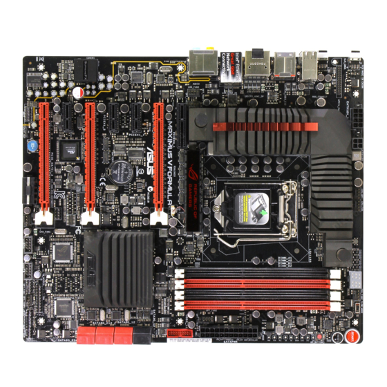
1.2.2 Motherboard layout Refer to 1.2.9 Internal connectors and 2.3.1 Rear I/O connection for more information about rear panel connectors and internal connectors. ASUS MAXIMUS V FORMULA Series... -
Page 26: Layout Contents
Layout contents Connectors/Jumpers/Buttons and switches/Slots 1. Power connectors (24-pin EATXPWR, 8-pin EATX12V, 4-pin EATX12V; 4-pin EZ_PLUG) 2. LGA1155 CPU Socket 3. CPU, chassis, and optional fan connectors (4-pin CPU_FAN, 4-pin CPU_OPT, 4-pin OPT_FAN1-3, 4-pin CHA_FAN1-3) 4. DDR3 DIMM slots 5. Q_Code LEDs 6. -
Page 27: Central Processing Unit (Cpu)
Contact your retailer immediately if the PnP cap is missing, or if you see any damage to the PnP cap/socket contacts/motherboard components. ASUS will shoulder the cost of repair only if the damage is shipment/ transit-related. -
Page 28: System Memory
1.2.4 System memory The motherboard comes with four Double Data Rate 3 (DDR3) Dual Inline Memory Modules (DIMM) slots. A DDR3 module is notched differently from a DDR or DDR2 module. DO NOT install a DDR or DDR2 memory module to the DDR3 slot. Recommended memory configurations 1-10 Chapter 1: Product introduction... -
Page 29: Memory Configurations
3.3 Extreme Tweaker menu for manual memory frequency adjustment. • For system stability, use a more efficient memory cooling system to support a full memory load (4 DIMMs) or overclocking condition. ASUS MAXIMUS V FORMULA Series support site at http://support.microsoft. ® 1-11... - Page 30 MAXIMUS V FORMULA Series Motherboard Qualified Vendors Lists (QVL) DDR3 2400 MHz capability Vendors Part No. CORSAIR CMGTX8(XMP) CORSAIR CMGTX3(XMP) G.SKILL F3-19200CL11Q- 16GBZHD (XMP) G.SKILL F3-19200CL11Q- 16GBZHD (XMP) G.SKILL F3-19200CL9Q-16GBZMD (XMP) G.SKILL F3-19200CL10Q- 32GBZHD (XMP) G.SKILL F3-19200CL9D-4GBPIS (XMP) GEIL GOC316GB2400C10QC...
- Page 31 16GBXLD(XMP) G.SKILL F3-17000CL9Q-16GBZH(XMP) G.SKILL F3-17066CL9Q- 16GBTDD(XMP) G.SKILL F3-17000CL11Q2- 64GBZLD(XMP) G.SKILL F3-17066CL9D-8GBPID(XMP) KINGSTON KHX2133C11D3K4/16GX(XMP) OCZ3XTEP2133C9LV4GK Patriot PVV34G2133C9K(XMP) ASUS MAXIMUS V FORMULA Series Size Chip Chip Timing Brand 9-11-9-27 9-9-9-24 16GB (4x4GB) 9-11-9-27 8GB (2x4GB) 9-9-9-24 4GB (2x2GB) 9-10-9-24 4GB (2x2GB) 9-9-9-24...
- Page 32 DDR3 2000 MHz capability Vendors Part No. A-DATA AX3U2000GB2G9B (XMP) A-DATA AX3U2000GC4G9B (XMP) Apacer 78.AAGD5.9KD(XMP) CORSAIR CMZ4GX3M2A2000C10 (Ver 5.12) (XMP) CORSAIR CMT6GX3M3A2000C8 (XMP) G.SKILL F3-16000CL9D-4GBRH (XMP) G.SKILL F3-16000CL9D-4GBTD (XMP) GEIL GUP34GB2000C9DC (XMP) Transcend TX2000KLN-8GK(388375) (XMP) AEXEA AXA3ES2G2000LG28V (XMP) AEXEA AXA3ES4GK2000LG28V (XMP) Asint SLA302G08-ML2HB...
- Page 33 Patriot PXD38G1866ELK(XMP) 8GB (2x4GB) Patriot PXD38G1866ELK(XMP) 8GB (2x4GB) Team TXD34096M1866HC9K -L(XMP) DDR3 1800 MHz capability Vendors Part No. G.SKILL F3-14400CL9D-4G BRL(XMP) ASUS MAXIMUS V FORMULA Series Chip Chip NO. Timing Brand 9-11-9-27 9-11-9-27 9-10-9-27 10-11- 10-27 9-10-9-27 9-9-9-27 9-10-9-28 9-10-9-28...
- Page 34 DDR3 1600 MHz capability Vendors Part No. A-DATA AM2U16BC2P1 A-DATA AM2U16BC4P2 A-DATA AX3U1600GC4G9 ( XMP) A-DATA AX3U1600PC4G8 (XMP) CORSAIR CMZ8GX3M4X1600C9 (Ver2.12)(XMP) CORSAIR HX3X12G1600C9 (XMP) CORSAIR CML16GX3M4X1600C8 (Ver 2.12)(XMP) CORSAIR CMZ16GX3M4A1600C9 (XMP) CORSAIR CMZ32GX3M4X1600C10 (Ver2.2)(XMP) CORSAIR CMG4GX3M2A1600C6 CORSAIR CMP6GX3M3A1600C8 (XMP) CORSAIR CMP6GX3M3A1600C8 (XMP) CORSAIR...
- Page 35 KHX1600C9D3P1K2/ 8GB (2x4GB) OCZ3BE1600C8LV4GK 4GB(2x2GB) Transcend TS256MLK64V6N Transcend TS512MLK64V6N Transcend JM1600KLN-8GK 8GB (2x4GB) Asint SLZ3128M8- EGJ1D(XMP) Asint SLA302G08- EGG1C(XMP) ASUS MAXIMUS V FORMULA Series Chip Chip Timing Brand 9-9-9- 8-8-8- 9-9-9- 7-7-7- KINGMAX 9-9-9- KINGMAX 9-9-9- 9-9-9- 8-8-8 Transcend K4B2G...
- Page 36 DDR3 1600 MHz capability Vendors Part No. Asint SLA302G08-EGG1C (XMP) Asint SLA302G08-EGJ1C (XMP) AQ12M64B8BKK0S EK Memory EKM324L28BP8-I16 (XMP) EK Memory EKM324L28BP8-I16 (XMP) Elixir M2X2F64CB88G7N- DG(XMP) Elixir M2X4G64CB8HG5N- DG(XMP) GoodRam GR1600D364L9/2G KINGTIGER KTG2G1600PG3 (XMP) Mushkin 996805(XMP) Mushkin 998805(XMP) Patriot AE32G1609U1-U Patriot PX7312G1600LLK (XMP) Patriot...
- Page 37 KINGMAX FLFD45F-B8KL9 KINGSTON KVR1333D3N9/ 2G MICRON MT16JTF1G64A Z-1G4D1 SAMSUNG M378B5773DH0- SAMSUNG M378B5273DH0- Elixir M2F2G64CB88G 7N-CG Elixir M2F4G64CB8HD 5N-CG ASUS MAXIMUS V FORMULA Series Chip Chip NO. Timing Voltage Brand Team T3D1288L 7-7-7- 1.65 T-16 Team T3D1288R 8-8-8- 1.65 T-16 Team...
- Page 38 Hyper DIMM support is subject to the physical characteristics of individual CPUs. Load the X.M.P. or D.O.C.P. settings in the BIOS for the hyper DIMM support. • Visit the ASUS website for the latest QVL. 1-20 Chapter 1: Product introduction...
-
Page 39: Expansion Slots
Slot No. Slot Description PCIe 2.0 x4_1 slot PCIe 3.0/2.0 x16/x8_1 slot PCIe 2.0 x1_1 slot PCIe 2.0 x1_2 slot PCIe 3.0/2.0 x8/x4_2 slot PCIe 2.0 x1_3 slot PCIe 2.0 x4/x1_3 slot ASUS MAXIMUS V FORMULA Series 1-21... - Page 40 Configuration PCIe_x16/x8_1 x 16 at Max. GEN3 Configuration 1 (single VGA recommended) x8 at Max. GEN3 Configuration 2 (SLI/CFX recommended) x8 at Max. GEN3 Configuration 3 (3-WAY CFX recommended) • We recommend that you provide sufficient power when running CrossFireX™ or SLI™ mode.
- Page 41 EHCI# 1 (USB 2.0) – XHCI (USB 3.0) shared Asmedia USB 3.0 shared Controller ASM1061 Storage shared Controller #0 ASM1061 Storage shared Controller #1 ASUS MAXIMUS V FORMULA Series – – – – shared – – – – shared – –...
-
Page 42: Onboard Buttons And Switches
1.2.6 Onboard buttons and switches Onboard switches and buttons allow you to fine-tune performance when working on a bare or open-case system. This is ideal for overclockers and gamers who continually change settings to enhance system performance. Power-on button The motherboard comes with a power-on button that allows you to power up or wake up the system. - Page 43 C cooling system. When enabled, the Slow Mode switch prevents the system from crashing, slows down the CPU, and the system’s tuner will make the adjustments. Ensure to set the LN2 Mode jumper to [Enable] before using the Slow Mode Switch. ASUS MAXIMUS V FORMULA Series 1-25...
-
Page 44: Jumpers
1.2.7 Jumpers LN2 Mode Jumper (3-pin LN2) When enabled, the LN2 Mode jumper allows your system to eliminate the cold bugs in the processor during POST. It allows the processor to run at an extremely low temperature and helps the system boot fast. 1-26 Chapter 1: Product introduction... -
Page 45: Onboard Leds
GO LED Blinking: Indicates that MemOK! is enabled before POST. Lighting: Indicates that the system loads the preset profile (GO_Button file) for temporary overclocking when in OS. ASUS MAXIMUS V FORMULA Series 1-27... - Page 46 Q LED Q LEDs check key components (CPU, DRAM, VGA card, and booting devices) in sequence during motherboard booting process. If an error is found , the corresponding LED will continue lighting until the problem is solved. This user-friendly design provides an intuitive way to locate the root problem within seconds.
- Page 47 System Agent initialization after microcode loading PCH initialization after microcode loading Cache initialization 0C – 0D Reserved for future AMI SEC error codes Microcode not found Microcode not loaded PEI Core is started ASUS MAXIMUS V FORMULA Series (continued on the next page) 1-29...
-
Page 48: Q-Code Table
Q-Code table Code Description 11 – 14 Pre-memory CPU initialization is started 15 – 18 Pre-memory System Agent initialization is started 19 – 1C Pre-memory PCH initialization is started 2B – 2F Memory initialization Reserved for ASL (see ASL Status Codes section below) Memory Installed 32 –... - Page 49 S3 Resume is stared (S3 Resume PPI is called by the DXE IPL) S3 Boot Script execution Video repost OS S3 wake vector call E4 – E7 Reserved for future AMI progress codes S3 Resume Failed S3 Resume PPI not Found ASUS MAXIMUS V FORMULA Series (continued on the next page) 1-31...
- Page 50 Code Description S3 Resume Boot Script Error S3 OS Wake Error EC – EF Reserved for future AMI error codes Recovery condition triggered by firmware (Auto recovery) Recovery condition triggered by user (Forced recovery) Recovery process started Recovery firmware image is found Recovery firmware image is loaded F5 –...
- Page 51 Setup Input Wait Reserved for ASL (see ASL Status Codes section below) Ready To Boot event Legacy Boot event Exit Boot Services event Runtime Set Virtual Address MAP Begin ASUS MAXIMUS V FORMULA Series (continued on the next page) 1-33...
- Page 52 Code Description Runtime Set Virtual Address MAP End Legacy Option ROM Initialization System Reset USB hot plug PCI bus hot plug Clean-up of NVRAM Configuration Reset (reset of NVRAM settings) B8– BF Reserved for future AMI codes CPU initialization error System Agent initialization error PCH initialization error Some of the Architectural Protocols are not available...
- Page 53 System is waking up from the S4 sleep state 0xAC System has transitioned into ACPI mode. Interrupt controller is in PIC mode. 0xAA System has transitioned into ACPI mode. Interrupt controller is in APIC mode. ASUS MAXIMUS V FORMULA Series 1-35...
-
Page 54: Internal Connectors
1.2.9 Internal connectors Intel Z77 Serial ATA 6.0 Gb/s connectors (7-pin SATA6G_1/2 [red]) ® These connectors connect to Serial ATA 6.0 Gb/s hard disk drives via Serial ATA 6.0 Gb/s signal cables. If you installed Serial ATA hard disk drives, you can create a RAID 0, 1, 5, and 10 configuration with the Intel chipset. - Page 55 ATA hard disk drives. The Serial ATA RAID feature is available only if you are using Windows XP SP3 or later versions. ® ASUS MAXIMUS V FORMULA Series Rapid Storage Technology through the onboard Intel XP Service Pack 3 or later versions before using Serial ®...
- Page 56 Asmedia Serial ATA 6.0 Gb/s connectors (7-pin SATA6G_E12/E34 [red]) ® These connectors connect to Serial ATA 6.0 Gb/s hard disk drives via Serial ATA 6.0 Gb/s signal cables. You must install Windows hard disk drives. 1-38 XP Service Pack 3 or later versions before using Serial ATA ®...
- Page 57 This connector is for an additional Sony/Philips Digital Interface (S/PDIF) port. Connect the S/PDIF Out module cable to this connector, then install the module to a slot opening at the back of the system chassis. The S/PDIF module is purchased separately. ASUS MAXIMUS V FORMULA Series 1-39...
- Page 58 Never connect a 1394 cable to the USB connectors. Doing so will damage the motherboard! You can connect the front panel USB cable to the ASUS Q-Connector (USB, blue) first, and then install the Q-Connector (USB) to the USB connector onboard if your chassis supports front panel USB ports.
- Page 59 The CPU_FAN connector supports the CPU fan of maximum 1A (12 W) fan power. • If you install two VGA cards, we recommend that you plug the rear chassis fan cable to the motherboard connector labeled CHA_FAN1, CHA_FAN2, CHA_FAN3 for better thermal environment. ASUS MAXIMUS V FORMULA Series 1-41...
- Page 60 Front panel audio connector (10-1 pin AAFP) This connector is for a chassis-mounted front panel audio I/O module that supports either HD Audio or legacy AC`97 audio standard. Connect one end of the front panel audio I/O module cable to this connector. •...
- Page 61 1000W power or above to ensure the system stability. • If you are uncertain about the minimum power supply requirement for your system, refer to the Recommended Power Supply Wattage Calculator at http://support.asus. com/PowerSupplyCalculator/PSCalculator.aspx?SLanguage=en-us for details. ASUS MAXIMUS V FORMULA Series...
-
Page 62: System Panel Connector
System panel connector (20-8 pin PANEL) This connector supports several chassis-mounted functions. • System power LED (2-pin PLED) This 2-pin connector is for the system power LED. Connect the chassis power LED cable to this connector. The system power LED lights up when you turn on the system power, and blinks when the system is in sleep mode. - Page 63 The optional fan 1/2/3 can work with the temperature sensors for a better cooling effect. You must enable the OPT FAN 1/2/3 overheat protection in BIOS if you connect the thermal sensor cables to these connectors. The thermal sensor cables are purchased separately. ASUS MAXIMUS V FORMULA Series 1-45...
- Page 64 ROG Logo LED connector (3-pin ROG) This connector is for the box (labeled Republic of Gamers) on the heatpipe assembly. Connect the box’s cable, and it lights up when you turn on the system. Chapter 1: Product introduction 1-46...
-
Page 65: Fusion Thermo
• Ensure to keep the chassis ventilation airflow in one direction. • Refer to the technical documentation of your water cooling kit for assembly instructions. ASUS MAXIMUS V FORMULA Series Nickel barb 1-47... - Page 66 Chapter 1: Product introduction 1-48...
-
Page 67: Chapter 2: Basic Installation
The diagrams in this section are for reference only. The motherboard layout may vary with models, but the installation steps are the same for all models. Install the ASUS Q-Shield to the chassis rear I/O panel. ASUS MAXIMUS V FORMULA Series... - Page 68 Place the motherboard into the chassis, ensuring that its rear I/O ports are aligned to the chassis’ rear I/O panel. Chapter 2: Getting started...
- Page 69 Place ten screws into the holes indicated by circles to secure the motherboard to the chassis. DO NOT overtighten the screws! Doing so can damage the motherboard. ASUS MAXIMUS V FORMULA Series...
-
Page 70: Cpu Installation
2.1.2 CPU installation The LGA1156 CPU is not compatible with the LGA1155 socket. DO NOT install a LGA1156 CPU on the LGA1155 socket. Chapter 2: Getting started... -
Page 71: Cpu Heatsink And Fan Assembly Installation
2.1.3 CPU heatsink and fan assembly installation To install the CPU heatsink and fan assembly ASUS MAXIMUS V FORMULA Series Apply the Thermal Interface Material to the CPU heatsink and CPU before you install the heatsink and fan if necessary. - Page 72 To uninstall the CPU heatsink and fan assembly Chapter 2: Getting started...
-
Page 73: Dimm Installation
2.1.4 DIMM installation To remove a DIMM ASUS MAXIMUS V FORMULA Series... -
Page 74: Atx Power Connection
2.1.5 ATX Power connection Chapter 2: Getting started... -
Page 75: Sata Device Connection
2.1.6 SATA device connection ASUS MAXIMUS V FORMULA Series... -
Page 76: Front I/O Connector
2.1.7 Front I/O Connector To install ASUS Q-Connector To install USB 2.0 connector To install front panel audio connector AAFP USB 2.0 To install USB 3.0 connector USB 3.0 Chapter 2: Getting started 2-10... -
Page 77: Expansion Card Installation
2.1.8 Expansion Card installation To install PCIe x16 cards To install PCIe x1 cards ASUS MAXIMUS V FORMULA Series 2-11... -
Page 78: Mpcie Combo Installation
2.1.9 mPCIe Combo installation The mPCIe Combo is a mini card that allows you to add an mPCIe module and an mSATA module into your motherboard. • The mPCIe Combo supports half-sized mPCIe modules (26.8mm x 30mm) only. • The mPCIe Combo supports full-sized and hald-sized mSATA modules. The suggested sizes are from 50.8mm x 30mm to 26.8mm x 30mm. - Page 79 DO NOT overtighten the screws to prevent damage to the mPCIe Wi-Fi module or mPCIe Combo. Be sure to install the Bluetooth driver before installing the Wi-Fi GO! software. Remove the screw beside the 26-pin connector. ASUS MAXIMUS V FORMULA Series 2-13...
- Page 80 Locate the mPCIe_Combo connector on the motherboard. Align and insert the mPCIe Combo on the connector. • The mPCIe Combo fits in one orientation only. • Insert the mPCIe Combo with caution to prevent damage to the module, or the mCPIe_Combo connector pins, or the motherboard.
- Page 81 The Wi-Fi antenna and its cables are purchased separately. Re-attach the bolt on the connector. antenna connector washer Connect the opposite end of the Wi-Fi antenna connector to the pins located on the mPCIe Wi-Fi card. ASUS MAXIMUS V FORMULA Series bolt I/O Shield 2-15...
-
Page 82: Installing The Msata Module
Installing the mSATA module To install the mSATA module: Unlock the mSATA clip. Insert the mSATA card into the MSATA slot. The mSATA card fits in one orientation only. Lock the mSATA clip. 2-16 Chapter 2: Getting started... - Page 83 Locate the mPCIe_Combo connector on the motherboard. Align and insert the mPCIe Combo on the connector. • The mPCIe Combo fits in one orientation only. • Insert the mPCIe with caution to prevent damage to the module, or the mPCIe_Combo connector pins, or the motherboard. ASUS MAXIMUS V FORMULA Series 2-17...
- Page 84 Secure the mPCIe Combo in place with the screw removed in step 4. Chapter 2: Getting started 2-18...
-
Page 85: Bios Update Utility
• Updating BIOS may have risks. If the BIOS program is damaged during the process and results to the system’s failure to boot up, please contact your local ASUS Service Center. ASUS MAXIMUS V FORMULA Series... -
Page 86: Motherboard Rear And Audio Connections
5. ROG Connect button 6. USB 2.0 ports 7. USB 2.0 port, also ROG Connect port 8. ASMedia USB 3.0 ports, support ASUS USB 3.0 Boost UASP Mode 9. HDMI port 10. DisplayPort 11. Intel USB 3.0 ports, support ASUS USB 3.0 Boost Turbo Mode. -
Page 87: Audio I/O Connections
Mic In Orange – – Black – Rear Speaker Out 2.3.2 Audio I/O connections Audio I/O ports ASUS MAXIMUS V FORMULA Series Speed LED Status Description 10 Mbps connection ORANGE 100 Mbps connection GREEN 1 Gbps connection 6-channel Line In... - Page 88 Connect to Headphone and Mic Connect to Stereo Speakers Connect to 2.1 channel Speakers Chapter 2: Getting started 2-22...
- Page 89 Connect to 4.1 channel Speakers Connect to 5.1 channel Speakers ASUS MAXIMUS V FORMULA Series 2-23...
- Page 90 Connect to 7.1 channel Speakers When the DTS UltraPC II function is enabled, ensure to connect the rear speaker to the gray port. Chapter 2: Getting started 2-24...
-
Page 91: Starting Up For The First Time
BIOS setting. Press the power switch for more than four seconds to let the system enter the soft-off mode regardless of the BIOS setting. ASUS MAXIMUS V FORMULA Series Description VGA detected... - Page 92 Chapter 2: Getting started 2-26...
-
Page 93: Chapter 3: Bios Setup
BIOS setup Knowing BIOS The new ASUS UEFI BIOS is a Unified Extensible Interface that complies with UEFI architecture, offering a user-friendly interface that goes beyond the traditional keyboard- only BIOS controls to enable a more flexible and convenient mouse input. You can easily navigate the new UEFI BIOS with the same smoothness as your operating system. -
Page 94: Bios Setup Program
BIOS setup program Use the BIOS Setup to update the BIOS or configure its parameters. The BIOS screen include navigation keys and brief onscreen help to guide you in using the BIOS Setup program. Entering BIOS at startup To enter BIOS Setup at startup: •... -
Page 95: Ez Mode
The boot device options vary depending on the devices you installed to the system. The Boot Menu(F8) button is available only when the boot device is installed to the • system. ASUS MAXIMUS V FORMULA Series Selects the display language of the BIOS setup program Exits the BIOS setup program without saving... -
Page 96: Advanced Mode
3.2.2 Advanced Mode The Advanced Mode provides advanced options for experienced end-users to configure the BIOS settings. The figure below shows an example of the Advanced Mode. Refer to the following sections for the detailed configurations. To access the Advanced Mode, click Exit, then select Advanced Mode or press F7 hotkey. Menu items Submenu item Menu bar... -
Page 97: Menu Items
You cannot select an item that is not user-configurable. A configurable field is highlighted when selected. To change the value of a field, select it and press <Enter> to display a list of options. ASUS MAXIMUS V FORMULA Series... -
Page 98: Extreme Tweaker Menu
Extreme Tweaker menu The Extreme Tweaker menu items allow you to configure overclocking-related items. Be cautious when changing the settings of the Ai Tweaker menu items. Incorrect field values can cause the system to malfunction. The configuration options for this section vary depending on the CPU and DIMM model you installed on the motherboard. - Page 99 Selecting a very high memory frequency may cause the system to become unstable! If this happens, revert to the default setting. Xtreme Tweaking [Disabled] This item may help improve some benchmarks performance. Configuration options: [Disabled] [Enabled] ASUS MAXIMUS V FORMULA Series...
-
Page 100: Dram Timing Control
EPU Power Saving Mode [Disabled] Allows you to enable or disable the EPU power saving function. Configuration options: [Disabled] [Enabled] EPU Setting [Auto] This item only appears when you set the EPU Power Saving Mode to [Enabled]. It allows you to set the EPU setting to power saving modes. Configuration options: [Auto] [Light Power Saving Mode] [Medium Power Saving Mode] [Max Power Saving Mode] DRAM Timing Control... - Page 101 DRAM RAS# ACT Time [Auto] Configuration options: [Auto] [1 DRAM Clock] – [255 DRAM Clock] DRAM COMMAND Mode [Auto] Configuration options: [Auto] [1 DRAM Clock] [2 DRAM Clock] [3 DRAM Clock] Latency Boundary Configuration options: [Auto] [1] - [14] ASUS MAXIMUS V FORMULA Series...
- Page 102 Secondary Timings DRAM RAS# to RAS# Delay [Auto] Configuration options: [Auto] [1 DRAM Clock] – [15 DRAM Clock] DRAM REF Cycle Time [Auto] Configuration options: [Auto] [1 DRAM Clock] – [511 DRAM Clock] DRAM Refresh Interval [Auto] Configuration options: [Auto] [1 DRAM Clock] – [65535 DRAM Clock] DRAM WRITE Recovery Time [Auto] Configuration options: [Auto] [1 DRAM Clock] –...
- Page 103 Channel B DIMM Control [Enable Both DIMMS] Configuration options: [Enable Both DIMMS] [Disable DIMM0] [Disable DIMM1] [Disable Both DIMMS] DRAM Read Additional Swizzle [Auto] Configuration options: [Auto] [Enabled] [Disabled] DRAM Write Additional Swizzle [Auto] Configuration options: [Auto] [Enabled] [Disabled] ASUS MAXIMUS V FORMULA Series 3-11...
-
Page 104: Cpu Power Management
GPU.DIMM Post The sub-items in this menu display the status of the installed VGA cards and memory. The fields show N/A if there are no devices installed on the slots. CPU Power Management The sub-items in this menu allow you to set the CPU ratio and features. CPU Ratio [Auto] Allows you to manually adjust the maximum non-turbo CPU ratio. - Page 105 [Standard] [Optimized] [Extreme] [Manual Adjustment] ASUS MAXIMUS V FORMULA Series The default power control phase mode Proceeds phase control depending on the CPU loading. Loads the ASUS optimized phase tuning profile. Proceeds the full phase mode. Allows manual adjustment. 3-13...
- Page 106 CPU Power Duty Control [T.Probe] [T.Probe] Maintains the VRM thermal balance. [Extreme] Maintains the VRM current balance. CPU Current Capability [Auto] This item provides wider total power range for overclocking. A higher value brings a wider total power range and extends the overclocking frequency range simultaneously. Configuration options: [100%] [110%] [120%] [130%] [140%] [150%] [OCP Disable] VRM Protection Threshold [Default] This item allows you to set the VRM protection threshold over temperature protection.
- Page 107 DRAM Power Phase control [Auto] [Auto] Allows you to set the default DRAM power phase control settings. [Optimized] Allows you to set ASUS optimized phase tuning profile. [Extreme] Allows you to set the Full phase mode. DRAM Power Thermal Control [110] A higher temperature brings a wider DRAM power thermal range, and extends the overclocking tolerance to enlarge the O.C.
- Page 108 CPU Manual Voltage [Auto] This item appears only when you set the CPU Voltage item to [Manual Mode] and allows you to set a fixed CPU voltage. The values range from 0.800V to 1.920V with a 0.005V interval. The 2.155V voltage is available only when the Extreme OV item is set to [Enabled].
- Page 109 CPU I/O Skew [Auto] Adjust this setting may allows you to increase the overclocking capability. Configuration options: [Auto] [-4]—[+4] DMI Skew [Auto] Adjust this setting may allows you to increase the overclocking capability. Configuration options: [Auto] [-4]—[+4] ASUS MAXIMUS V FORMULA Series 3-17...
- Page 110 PLL Skew [Auto] Adjust this setting may allows you to increase the overclocking capability. Configuration options: [Auto] [-12]—[+12] PCH CLK Driving [Auto] Adjust this setting may allows you to increase the overclocking capability. Configuration options: [Auto] [-8]—[+8] CPU Spread Spectrum [Auto] [Auto] Automatic configuration.
-
Page 111: Main Menu
RTC RAM via the Clear CMOS button. • The Administrator or User Password items on top of the screen show the default [Not Installed]. After you set a password, these items show [Installed]. ASUS MAXIMUS V FORMULA Series 3-19... -
Page 112: Administrator Password
Administrator Password If you have set an administrator password, we recommend that you enter the administrator password for accessing the system. Otherwise, you might be able to see or change only selected fields in the BIOS setup program. To set an administrator password: Select the Administrator Password item and press <Enter>. - Page 113 To clear the user password, follow the same steps as in changing a user password, but press <Enter> when prompted to create/confirm the password. After you clear the password, the User Password item on top of the screen shows Not Installed. ASUS MAXIMUS V FORMULA Series 3-21...
-
Page 114: Advanced Menu
Advanced menu The Advanced menu items allow you to change the settings for the CPU and other system devices. Be cautious when changing the settings of the Advanced menu items. Incorrect field values can cause the system to malfunction. SupremeFX IV Lighting LED [Enabled] This item allows you to turn on the SupremeFX VI Lighting LED. -
Page 115: Cpu Configuration
Allows you to choose the number of CPU cores to activate in each processor package. Configuration options: [All] [1] [2] [3] Limit CPUID Maximum [Disabled] [Enabled] Allows legacy operating systems to boot even without support for CPUs with extended CPUID functions. [Disabled] Disables this function. ASUS MAXIMUS V FORMULA Series 3-23... - Page 116 Execute Disable Bit [Enabled] [Enabled] Enables the No-Execution Page Protection Technology. [Disabled] Forces the XD feature flag to always return to zero (0). Intel Virtualization Technology [Disabled] ® [Enabled] Allows a hardware platform to run multiple operating systems separately and simultaneously, enabling one system to virtually function as several systems.
-
Page 117: Pch Configuration
Intel (R) Smart Connect Technology [Disabled] Allow you to enable or disable Intel Smart Connect Technology. Configuration options: [Enabled] [Disabled] ISCT Configuration [Disabled] Allows you to enable or disable ISCT Configuration. Configuration options: [Enabled] [Disabled] ASUS MAXIMUS V FORMULA Series 3-25... -
Page 118: Sata Configuration
3.5.3 SATA Configuration While entering Setup, the BIOS automatically detects the presence of SATA devices. The SATA Port items show Not Present if no SATA device is installed to the corresponding SATA port. Scroll down to display the other BIOS items. SATA Mode Selection [AHCI] Allows you to set the SATA configuration. -
Page 119: System Agent Configuration
Allows you to select the amount of system memory allocated to DVMT 5.0 used by the iGPU. Configuration options: [32M] [64M] [96M] [128M] [160M] [192M] [224M] [256M] [288M][320M] [352M] [384M] [416M] [448M] [480M] [512M] [1024M] ASUS MAXIMUS V FORMULA Series 3-27... -
Page 120: Usb Configuration
Render Standby [Enabled] Allows you to enable the Intel Graphics Render Standby support to reduce the iGPU power use when idle. Configuration options: [Disabled] [Enabled] iGPU Multi-Monitor [Disabled] Allows you to enable the iGPU Multi-Monitor. For Lucid Virtu MVP function supports, set this item to [Enabled] to empower both integrated and discrete graphics. - Page 121 [Smart Auto] Enables the operation of xHCI controller. [Enabled] Enables the function. [Disabled] Disables the function. EHCI Hand-off [Disabled] [Enabled] Enables the support for operating systems without an EHCI hand-off feature. [Disabled] Disables the function. ASUS MAXIMUS V FORMULA Series 3-29...
-
Page 122: Onboard Devices Configuration
3.5.6 Onboard Devices Configuration Scroll down to view the other BIOS items. HD Audio Controller [Enabled] [Enabled] Enables the High Definition Audio Controller. [Disabled] Disables the controller. The following two items appear only when you set the Azalia HD Audio item to [Enabled]. Front Panel Type [HD] Allows you to set the front panel audio connector (AAFP) mode to legacy AC’97 or high-definition audio depending on the audio standard that the front panel audio... - Page 123 Intel PXE OPROM [Disabled] This item appears only when you set the previous item to [Enabled]. It allows you to enable or disable the PXE OptionRom of the Intel 82579LAN controller. Configuration options: [Enabled] [Disabled] ASUS MAXIMUS V FORMULA Series 3-31...
-
Page 124: Apm
3.5.7 ErP Ready [Disabled] This item allows you to switch off some power at S5 to get the system ready for ErP requirement. When set to [Enabled], all other PME options will be switched off. Configuration options: [Disabled] [Enabled] Restore AC Power Loss [Power Off] [Power On] The system goes into on state after an AC power loss. -
Page 125: Network Stack
Configuration options: [Disable Link] [Enable] The following items appear only when you set the Network Stack to [Enabled]. Ipv4/Ipv6 PXE Support [Enabled] Allows you to enable or disable the Ipv4/Ipv6 PXE boot option. Configuration options: [Disabled Link] [Enabled] ASUS MAXIMUS V FORMULA Series 3-33... -
Page 126: Monitor Menu
Monitor menu The Monitor menu displays the system temperature/power status, and allows you to change the fan settings. Anti Surge Support [Enabled] This item allows you to enable or disable the Anti Surge function. Configuration options: [Disabled] [Enabled] Voltage Monitor CPU Voltage;... -
Page 127: Fan Speed Control
Use the <+> and <-> keys to adjust the minimum CPU fan duty cycle. The values range from 20% to 100%. When the CPU temperature is under 40ºC, the CPU fan will operate at the minimum duty cycle. ASUS MAXIMUS V FORMULA Series 3-35... - Page 128 Chassis Q-Fan Control 1/3 [Disabled] [Disabled] Disables the Chassis Q-Fan control feature. [Enabled] Enables the Chassis Q-Fan control feature. Chassis Fan Speed Low Limit 1/3 [600 RPM] This item appears only when you enable the Chassis Q-Fan Control feature and allows you to disable or set the chassis fan warning speed.
-
Page 129: Boot Menu
[Disabled] Disables the full screen logo display feature. Set this item to [Enabled] to use the ASUS MyLogo 2™ feature. Post Report [5 sec] This item appears only when you set Full Screen Logo to [Disabled]. This allows you to select a desired post epot waiting time. -
Page 130: Boot Option Priorities
Press <F5> when ASUS Logo appears. • Press <F8> after POST. • To select the boot device during system startup, press <F8> when ASUS Logo appears. Boot Override These items displays the available devices. The number of device items that appears on the screen depends on the number of devices installed in the system. -
Page 131: Tools Menu
3.8.1 ASUS EZ Flash 2 Utility Allows you to run ASUS EZ Flash 2. When you press <Enter>, a confirmation message appears. Use the left/right arrow key to select between [Yes] or [No], then press <Enter> to confirm your choice. -
Page 132: Asus Spd Information
• We recommend that you update the BIOS file only coming from the same memory/ CPU configuration and BIOS version. 3.8.3 ASUS SPD Information Allows you to view the DRAM SPD information. 3-40 Chapter 3: BIOS setup... -
Page 133: Go Button File
Allows you to load default settings. Save Above Settings Allows you to save the adjusted values for specific items as a GO Button file. Load from EEPROM setting Allows you to load from EEPROM setting. ASUS MAXIMUS V FORMULA Series 3-41... -
Page 134: Exit Menu
This option allows you to exit the Setup program without saving your changes. When you select this option or if you press <Esc>, a confirmation window appears. Select Yes to discard changes and exit. ASUS EZ Mode This option allows you to enter the EZ Mode screen. Launch EFI Shell from filesystem device This option allows you to attempt to launch the EFI Shell application (shellx64.efi) from one of... -
Page 135: Updating Bios
BIOS in the future. Copy the original motherboard BIOS using the ASUS Update or BIOS Updater utilities. 3.10.1 ASUS Update The ASUS Update is a utility that allows you to manage, save, and update the motherboard BIOS in Windows environment. ®... - Page 136 Launching ASUS Update To launch ASUS Update, click Update > ASUS Update on the AI Suite II main menu bar. Quit all Windows® applications before you update the BIOS using this utility. Updating the BIOS through the Internet To update the BIOS through the Internet:...
- Page 137 The screenshots in this section are for reference only. The actual BIOS information vary by models. • Refer to the software manual in the support DVD or visit the ASUS website at www.asus.com for detailed software configuration. ASUS MAXIMUS V FORMULA Series...
-
Page 138: Asus Ez Flash 2
3.10.2 ASUS EZ Flash 2 ASUS EZ Flash 2 allows you to update the BIOS without having to use a bootable floppy disk or an OS-based utility. Before you start using this utility, download the latest BIOS from the ASUS website at www.asus.com. -
Page 139: Asus Crashfree Bios 3
The BIOS file in the motherboard support DVD may be older than the BIOS file published on the ASUS official website. If you want to use the newer BIOS file, download the file at support.asus.com and save it to a USB flash drive. -
Page 140: Asus Bios Updater
3.10.4 ASUS BIOS Updater The ASUS BIOS Updater allows you to update the BIOS in DOS environment. This utility also allows you to copy the current BIOS file that you can use as a backup when the BIOS fails or gets corrupted during the updating process. - Page 141 Press <Tab> to switch between screen fields and use the <Up/Down/Home/End> keys to select the BIOS file and press <Enter>. BIOS Updater checks the selected BIOS file and prompts you to confirm BIOS update. Are you sure to update BIOS? ASUS MAXIMUS V FORMULA Series Update ROM BOARD: UNKNOWN...
- Page 142 Select Yes and press <Enter>. When BIOS update is done, press <ESC> to exit BIOS Updater. Restart your computer. DO NOT shut down or reset the system while updating the BIOS to prevent system boot failure! • For BIOS Updater version 1.04 or later, the utility automatically exits to the DOS prompt after updating BIOS.
-
Page 143: Chapter 4: Software Support
Support DVD information The contents of the support DVD are subject to change at any time without notice. Visit the ASUS website at www.asus.com for updates. 4.2.1 Running the support DVD Place the support DVD into the optical drive. -
Page 144: Obtaining The Software Manuals
The software manual files are in Portable Document Format (PDF). Install the Adobe Acrobat® Reader from the Utilities menu before opening the files. Click the Manual tab. Click ASUS Motherboard Utility Guide from the manual list on the left. -
Page 145: Software Information
4.3.1 AI Suite II AI Suite II is an all-in-one interface that integrates several ASUS utilities and allows users to launch and operate these utilities simultaneously. Installing AI Suite II To install AI Suite II on your computer: Place the support DVD to the optical drive. -
Page 146: Turbov Evo
To launch TurboV EVO, click Tool > TurboV EVO on the AI Suite II main menu bar. Refer to the software manual in the support DVD or visit the ASUS website at www.asus. com for detailed software configuration. TurboV EVO... - Page 147 Using Advanced Mode Click on the Advanced Mode tab to adjust the advanced voltage settings. Target values Current values Click to restore all startup settings ASUS MAXIMUS V FORMULA Series Voltage Adjustment bars Undoes all the changes Applies all the...
- Page 148 CPU Level Up ASUS TurboV EVO provides you with these three CPU Level Up modes for the most flexible CPU auto-tuning options. • The overclocking result varies with the CPU model and the system configuration. • We recommend that you set up a better thermal environment to prevent overheating from damaging the motherboard.
-
Page 149: Digi+ Power Control
4.3.3 DIGI+ Power Control ASUS DIGI+ Power Control allows you to adjust VRM voltage and frequency modulation to enhance reliability and stability. It also provides the highest power efficiency, generating less heat to prolong the component lifespan and minimize power loss. - Page 150 CPU Power Phase Control Increase phase number under heavy system loading to get more transient and better thermal performance. Reduce phase number under light system loading to increase VRM efficiency. VRM Protection Threshold It allows you to set the VRM protection to your motherboard from overheating accidents.
- Page 151 OC Range. DRAM Power Phase Control Select Extreme for full phase mode to increase system performance or select Optimized for ASUS optimized phase tuning profile to increase DRAM power efficiency. DRAM Power Thermal Control A higher temperature brings a wider DRAM power thermal range, and extends the overclocking tolerance to enlarge overclocking potential.
-
Page 152: Epu
*Select From the Last Reset to show the total CO2 that has been reduced since you • click the Clear button • Refer to the software manual in the support DVD or visit the ASUS website at www. asus.com for detailed software configuration. 4-10 Displays the following message if no VGA power saving engine is detected. -
Page 153: Fan Xpert 2
To use Fan Auto Tuning: Click Fan Auto Tuning on the FAN Xpert 2 main menu. Wait for the Fan Auto Tuning Process to complete, then click Next. ASUS MAXIMUS V FORMULA Series 4-11... - Page 154 Do not remove your fan during the Fan Auto Tuning process. From the Fan Position screen, check and assign the locations of your fans, then click OK to exit the screen. Select any of these fan customized settings for each fan. Silent: Minimized fan speed for silent fan operation.
- Page 155 Indicates the current CPU fan temperature Click these to switch between CPU and chassis fan screens ASUS MAXIMUS V FORMULA Series allows you to adjust the reaction speed for fan Click to switch window to Advanced Mode Click to adjust the Fan...
- Page 156 RPM Fixed Mode The RPM Fixed Mode tab allows you to set your fan speed when CPU temperature is below 75 degrees. Click and drag to make the adjustments • To protect your CPU, the fan will not automatically turn off even if you set the CPU fan power to 0.
- Page 157 Click to see the results in table format Click to see the results in graph format ASUS MAXIMUS V FORMULA Series to see the details of each detected fan. You can click on to see the results. 4-15...
-
Page 158: Usb 3.0 Boost
Turbo mode or UASP mode (if UASP is supported by the USB 3.0 device). You can manually switch the USB 3.0 mode back to Normal mode at any time. • Refer to the software manual in the support DVD or visit the ASUS website at www. asus.com for detailed software configuration. •... -
Page 159: Ai Charger
** Actual charging speeds may vary depending on the charging rate and specifications of your USB device. • To ensure normal charging function, disconnect and reconnect your USB device every time you enable or disable Ai Charger+. ASUS MAXIMUS V FORMULA Series 4-17... -
Page 160: Usb Charger
Click the dropdown box, and select a proper charge mode when your PC is off, in Sleep Mode, or Hibernate Mode. • Disable: disables the USB fast-charging function. ASUS: fast-charges your connected ASUS devices. • Apple: fast-charges your connected Apple devices. •... - Page 161 Click the Disabling the charging function Click to stop charging your device. ASUS MAXIMUS V FORMULA Series to re-enable the fast-charging. Click to fast-charge your connected device.
-
Page 162: Probe Ii
4.3.9 Probe II Probe II is a utility that monitors the computer’s vital components, and detects and alerts you of any problem with these components. Probe II senses fan rotations, CPU temperature, and system voltages, among others. With this utility, you are assured that your computer is always at a healthy operating condition. -
Page 163: Sensor Recorder
Using Sensor Recorder Click on Voltage/ Temperature/ Fan Speed tabs for the status you want to monitor. Colored lines will automatically appear on the diagram to indicate the immediate changes in the system status. ASUS MAXIMUS V FORMULA Series 4-21... - Page 164 Using History Record Click the History Record tab and adjust the settings on the left for Record Interval and Record Duration according to need. Click Start Recording to start measuring and recording each sensor. To stop recording, click Recording again. To track the recorded contents, set Type/ Date/ Select display items to display the history details.
-
Page 165: Asus Update
Windows environment. ® Launching ASUS Update To launch ASUS Update, click Update > ASUS Update on the AI Suite II main menu bar. Using ASUS Update Select any of these options to update the BIOS: • Update BIOS from Internet Allows you to download the latest BIOS version from the ASUS website at www.asus. -
Page 166: Mylogo2
4.3.12 MyLogo2 MyLogo2 allows you to customize the boot logo, which is the image that appears on the screen during the Power On Self Tests (POST). Launching MyLogo2 To launch MyLogo2, click Update > MyLogo on the AI Suite II main menu bar. Using MyLogo Select the option that you want to use to update your boot logo, click Next and follow the instructions below. -
Page 167: Audio Configurations
® Realtek HD Audio Manager icon on the taskbar. Double-click on ® the icon to display the Realtek HD Audio Manager. ASUS MAXIMUS V FORMULA Series proprietary UAJ ® Audio Driver from the support DVD that ® Realtek HD Audio Manager ®... -
Page 168: Dts Connect
Realtek HD Audio Manager with DTS Connect and DTS UltraPC II for Windows Configuration option tabs (vary with the audio devices connected) Control settings Analog and digital connector status DTS Connect DTS Connect allows you to select an audio mode for a digital surround sound media entertainment. - Page 169 Configuration options Control settings window Information button • Refer to the software manual in the support DVD or visit the ASUS website at www. asus.com for detailed software configuration. • Due to Intel Z77 platform does not support Windows ®...
-
Page 170: Rog Connect
4.3.14 ROG Connect ROG Connect allows you to monitor and adjust the local PC through your remote PC. Setting up USB connection between your local and remote PC • Install ROG Connect on the remote PC from the provided Support DVD before using ROG Connect. - Page 171 String and Code. RC Remote RC Remote allows you to operate your local system through the ROG Connect cable. RC Diagram RC Diagram allows you to monitor and record your local system status. ASUS MAXIMUS V FORMULA Series 4-29...
-
Page 172: Gamefirst Ii
GameFirst II attaches itself to Windows network stack to perform packet inspection, which is useful to online gamers and VOIP users. To launch GameFirst, click Start > All Programs > ASUS > ROG GameFirst II. Using EZ Mode Network... - Page 173 Adapter Info: Allows you to view the information of the adapters in your computer. • Online Budgets: Allows you to set an online budget time to your network adapters. • Traffic Analysis: Allows you to assign protocols and programs in one set. • ASUS MAXIMUS V FORMULA Series operating systems. ® 4-31...
-
Page 174: Memtweakit
4.3.16 MemTweakIt MemTweakIt allows you to adjust the timing of your installed memory. It also allows you to save, validate and post your configuration on the ROG website depending on your DRAM Efficency Score. To use MemTweakIt: Double-click on the desktop. Click the dropdown lists of your selected timings and select a timing value. - Page 175 Click OK to exit MemTweakIt. Validating and saving your MemTweakIt settings To validate and save your configuration online: Launch MemTweakIt and click Validate. In Online Mode, key in your ASUS account ID and password, and click Submit. Your configuration will be displayed in MemTweakIt webpage.
- Page 176 Key in a file name for your configuration file and click Save. Click validation webpage. In MemTweakIt - Validation File Upload window, key in your ASUS account ID and password. Click Browse, locate the saved .cvf file, and click Open.
-
Page 177: Chapter 5: Raid Support
RAID 0 and RAID 1 configurations. Use four new hard disk drives or use an existing drive and three new drives for this setup. ASUS MAXIMUS V FORMULA Series XP Service Pack 3 or later versions before using Serial ®... -
Page 178: Installing Serial Ata Hard Disks
5.1.2 Installing Serial ATA hard disks The motherboard supports Serial ATA hard disk drives. For optimal performance, install identical drives of the same model and capacity when creating a disk array. To install the SATA hard disks for a RAID configuration: Install the SATA hard disks into the drive bays. -
Page 179: Intel ® Rapid Storage Technology Option Rom Utility
The RAID BIOS setup screens shown in this section are for reference only and may not exactly match the items on your screen. The utility supports maximum four hard disk drives for RAID configuration. ASUS MAXIMUS V FORMULA Series All Rights Reserved. [ MAIN MENU ] 4. - Page 180 Creating a RAID set To create a RAID set: From the utility main menu, select 1. Create RAID Volume and press <Enter>. The following screen appears: Intel(R) Rapid Storage Technology - Option ROM - v10.5.1.1070 Copyright(C) 2003-10 Intel Corporation. Enter a unique volume name that has no special characters and is 16 characters or less.
- Page 181 WARNING: ALL DATA ON SELECTED DISKS WILL BE LOST. Are you sure you want to create this volume? (Y/N): Press <Y> to create the RAID volume and return to the main menu, or <N> to go back to the CREATE VOLUME menu. ASUS MAXIMUS V FORMULA Series...
- Page 182 Deleting a RAID set Be cautious when deleting a RAID set. You will lose all data on the hard disk drives when you delete a RAID set. To delete a RAID set: From the utility main menu, select 2. Delete RAID Volume and press <Enter>. The following screen appears: Name Level...
- Page 183 Rapid Storage Technology Option ROM utility ® To exit the utility: From the utility main menu, select 5. Exit, and then press <Enter>. The following warning message appears: Are you sure you want to exit? (Y/N): ASUS MAXIMUS V FORMULA Series [ CONFIRM EXIT ]...
-
Page 184: Creating A Raid Driver Disk
Creating a RAID driver disk A floppy disk with the RAID driver is required when installing a Windows on a hard disk drive that is included in a RAID set. • The motherboard does not provide a floppy drive connector. You have to use a USB floppy disk drive when creating a SATA RAID driver disk. -
Page 185: Installing The Raid Driver During Windows ® Os Installation
Before loading the RAID driver from a USB flash drive, you have to use another computer to copy the RAID driver from the support DVD to the USB flash drive. ASUS MAXIMUS V FORMULA Series ® 7 or later OS: ®... -
Page 186: Using A Usb Floppy Disk Drive
5.2.4 Using a USB floppy disk drive Due to OS limitation, Windows install the RAID driver from a floppy disk during the OS installation. To solve this issue, add the USB floppy disk drive’s Vendor ID (VID) and Product ID (PID) to the floppy disk containing the RAID driver. - Page 187 [HardwareIds.scsi.iaAHCI_ DesktopWorkstationServer] id= “PCI\VEN_8086&DEV_1C02&CC_0106”,”iaStor” id= “USB\VID_03EE&PID_6901”, “usbstor” [HardwareIds.scsi.iaStor_ DesktopWorkstationServer] id= “PCI\VEN_8086&DEV_2822&CC_0104”,”iaStor” id= “USB\VID_03EE&PID_6901”, “usbstor” Add the same line to both sections. The VID and PID vary with different vendors. Save and exit the file. ASUS MAXIMUS V FORMULA Series 5-11...
- Page 188 Chapter 5: RAID configurations 5-12...
-
Page 189: Chapter 6: Multiple Gpu Support
For Windows 7, go to Control Panel > Programs and Features. Select your current graphics card driver/s. For Windows XP, select Add/Remove. For Windows 7, select Uninstall. Turn off your computer. ASUS MAXIMUS V FORMULA Series CrossFireX™ technology that allows you to install ®... -
Page 190: Installing Two Crossfirex™ Graphics Cards
6.1.3 Installing two CrossFireX™ graphics cards The following pictures are for reference only. The graphics cards and the motherboard layout may vary with models, but the installation steps remain the same. Prepare two CrossFireX-ready graphics cards. Insert the two graphics card into the PCIEX16 slots. -
Page 191: Installing Three Crossfirex™ Graphics Cards
Ensure that the connectors are firmly in place. Connect three independent auxiliary power sources from the power supply to the three graphics cards separately. Connect a VGA or a DVI cable to the graphics card. ASUS MAXIMUS V FORMULA Series... -
Page 192: Installing The Device Drivers
6.1.5 Installing the device drivers Refer to the documentation that came with your graphics card package to install the device drivers. Ensure that your PCI Express graphics card driver supports the AMD® CrossFireX™ technology. Download the latest driver from the AMD website (www.amd.com). 6.1.6 Enabling the AMD After installing your graphics cards and the device drivers, enable the CrossFireX™... - Page 193 Enabling Dual CrossFireX technology In the Catalyst Control Center window, click Performance > AMD CrossFireX Select Enable CrossFireX Select a GPU combination from the drop-down list. Click Apply to save and activate the GPU settings made. ASUS MAXIMUS V FORMULA Series...
-
Page 194: Nvidia ® Sli™ Technology
NVIDIA ® The motherboard supports the NVIDIA allows you to install multi-graphics processing units (GPU) graphics cards. Follow the installation procedures in this section. 6.2.1 Requirements • In SLI mode, you should have two identical SLI-ready graphics cards that are NVIDIA certified. -
Page 195: Installing The Device Drivers
Refer to the documentation that came with your graphics card package to install the device drivers. Ensure that your PCI Express graphics card driver supports the NVIDIA Download the latest driver from the NVIDIA website (www.nvidia.com). ASUS MAXIMUS V FORMULA Series SLI bridge SLI™ technology. ®... -
Page 196: Enabling The Nvidia ® Sli™ Technology
6.2.4 Enabling the NVIDIA After installing your graphics cards and the device drivers, enable the SLI feature in NVIDIA® Control Panel under the Windows® 7 operating system. Launching the NVIDIA Control Panel You can launch the NVIDIA Control Panel by the following two methods. Right click on the empty space of the Windows Panel. - Page 197 Enabling SLI settings From the NVIDIA Control Panel window, select Configure SLI, Surround, PhysX. In the Quad-SLI enabled, click Maximize 3D Performance SLI to set the display for viewing SLI rendered content. When done, click Apply. ASUS MAXIMUS V FORMULA Series...
-
Page 198: Lucidlogix Virtu Mvp
Installing LucidLogix Virtu MVP To install LucidLogix Virtu MVP: Insert the support DVD in the optical drive. The ASUS Support Wizard appears if your computer has enabled the Autorun feature. Click the Utilites tab, then click LucidLogix Virtu MVP Software. -
Page 199: Setting Up Your Display
3D gaming performance. i-Mode (VGA output from motherboard) The motherboard’s IO ports and discrete graphic card is for reference only and may vary in different models. ASUS MAXIMUS V FORMULA Series d-Mode (VGA output from discrete graphics card) 6-11... -
Page 200: Configuring Lucidlogix Virtu Mvp
6.3.3 Configuring LucidLogix Virtu MVP Launch the Virtu MVP Control Panel to allow you to configure the main features, adjust the performance settings and select applications for graphical virtualization. To open the control panel, right-click LucidLogix Virtu MVP icon in the notification area and select Open Virtu MVP Control Panel. - Page 201 Performance Allows you to turn ON/OFF the Hyperformance or Virtual Vsync function. ® Click to turn Hyperformance® ON or OFF Click to turn Virtual Vsync ON or OFF ASUS MAXIMUS V FORMULA Series 6-13...
- Page 202 Applications Allows you to select applications for graphic virtualization. Click to select a program to run by discrete card, iGPU, or Hyperformance® Click to add, edit, or remove programs See the descriptions of these columns below: D column allows you to run applications with the discrete graphic card. Select D to •...
-
Page 203: Chapter 7: Intel ® Technologies
Rapid Start Technology, DRAM size smaller than 8GB is ® required. Ensure to enable the acceleration of Intel the partition for the Intel ASUS MAXIMUS V FORMULA Series 2012 Desktop responsiveness, your ® Smart Response Technology before creating ® Rapid Start Technology. - Page 204 SSD Capacity Requirements SSD Partition Capacity Requirements Intel Rapid Start ® Intel Smart Response ® Intel Smart Response ® Intel Rapid Start ® Intel Smart Response, ® Intel Rapid Start, ® Intel Smart Connect ® • The SSD used for Intel creating RAID.
-
Page 205: Intel ® Smart Response Technology
SSD and HDD at the same time. Maximized mode: WRITE BACK, write to SSD and write back to HDD in a later time. ASUS MAXIMUS V FORMULA Series Smart Response Technology, setting the SATA Mode BIOS item to Rapid Storage Technology Driver software. ®... -
Page 206: Intel ® Rapid Start Technology
Select Disable Acceleration to disable this function, and select Change Mode to switch acceleration mode to Enhanced/ Maximized. • To enable Intel and an HDD, and only one SSD can be assigned for caching. • If you want to restore the OS, go to BIOS Option ROM > Acceleration Options and remove the Disks/Volume Acceleration to disable Intel Technology. - Page 207 Go to Start > Control Panel > System and Security > System, and check the DRAM size information. The unallocated volume is allocated to the selected disk. ASUS MAXIMUS V FORMULA Series Smart Response to allow enough capacity for the ® ®...
- Page 208 To launch the disk partitioning tool, click Start > Programs > Accessories > Command Prompt tool. Type diskpart and press <Enter>. In the diskpart prompt, type list disk after DISKPART, and press <Enter>. Select the disk with the unallocated volume by typing select disk x (x = disk number), and press <Enter>.
- Page 209 ® Click the Show hidden icons arrow from the right side of the taskbar, and click Intel Manager icon. ASUS MAXIMUS V FORMULA Series Rapid Start Technology under the OS ® Rapid Start Manager to enable or disable the ®...
-
Page 210: Recovering The Partition
Tick On in the Status field to enable the function, and click Save. Click to enable or disable battery saving mode. This function only applies to notebooks. Click to enable or disable the timer. When enabled, move the scroll bar to the desired time. When the system is idle for more than the time period you set, the system automatically goes into the Intel Rapid Start mode. - Page 211 In the desktop, click Start, right-click Computer, and click Manage. In the Computer Management window, click Disk Management, right click the shrinked new volume, and select Extend Volume. As the Extend Volume Wizard appears, click Next. ASUS MAXIMUS V FORMULA Series...
-
Page 212: Intel ® Smart Connect Technology
Click Next after selecting the default selected disk. Extend volume setup is completed. Click Finish to recover the Intel Rapid Start Technology partition. Reboot the system after deleting the partition. Go to Start > Control Panel > Programs > Programs and Features to remove the Intel ®... -
Page 213: Using The Intel Smart Connect Technology
Updating. Clicking this button automatically disables the configuration in the Advanced tab. To reset to defaults, click Reset All to Defaults. ASUS MAXIMUS V FORMULA Series Smart Connect ® Smart Connect Technology. ® Click to view version information and help topics... - Page 214 In the Advanced tab, set up the schedule during low power usage time period for power saving. This setting only applies to the assigned time period. In the Help tab, click About to view the feature’s version. Click Topics to learn more about the Intel Smart Connect Technology and its configuration.
-
Page 215: Chapter 8: Thunderfx
Turn the knob to the desired audio source before connecting the USB cable. • Turn the knob to PS3 or Xbox 360 mode for analog signal output use such as iPhone, iPad, iPod or mp3 player. ASUS MAXIMUS V FORMULA Series... - Page 216 Volume control knob Turn the volume control knob to change the output volume from the external headset and microphone. Press the knob to select Master, Voice, or Game mode and turn it to control the volume. PS3 and Xbox 360 modes •...
-
Page 217: Rear Panel
USB 2.0 port Use the bundled Dual-head.USB cable to connect the ThunderFX with your PC, PS3, or Xbox 360 device. For more details on connecting your devices, refer to section 8.2 Connecting your devices. ASUS MAXIMUS V FORMULA Series... -
Page 218: Connecting Your Devices
Connecting your devices Switch to the desired mode first before connecting the Dual-head USB cable. Select the correct headphone impedance in the utility before turning on the ThunderFX. Chapter 7: Intel technologies ®... -
Page 219: Connecting To Pc
We recommend that you use the main connecting end of the Dual-head USB cable to your PC/consoles. The single-head end must be connected to your ThunderFX. • For power and signal stability, use both USB connections on the dual-head end for extra power under PC mode. USB 2.0 ASUS MAXIMUS V FORMULA Series... -
Page 220: Connecting To Playstation3
8.2.2 Connecting to PlayStation3™ USB 2.0 Chapter 7: Intel technologies ®... - Page 221 Select Audio Input Connector/SCART/AV MULTI. Select OK to continue. To configure the microphone: Go to Settings> Accessory Settings> Audio Device Settings. Go to Input Device and select ThunderFX. Go to Output Device and select ThunderFX. Select OK to continue. ASUS MAXIMUS V FORMULA Series...
-
Page 222: Connecting To Xbox 360
8.2.3 Connecting to Xbox 360™ Default Xbox 360™ connection USB 2.0 2.5mm Xbox 360 voice input cable Chapter 7: Intel technologies ®... - Page 223 Xbox 360™ connections with HDMI Use the ThunderFX Xbox 360 AV + 3.5mm to RCA cable to connect your Xbox 360 to the ThunderFX. ASUS MAXIMUS V FORMULA Series USB 2.0 2.5mm Xbox 360 voice input cable...
-
Page 224: Connecting To Iphone/ Ipod/ Ipad/ Mp3 Player
8.2.4 Connecting to iPhone/ iPod/ iPad/ MP3 player • Switch to PS3 or Xbox 360 mode before connecting your iPhone/ iPod/ iPad/ MP3 player. • Connect the ThunderFX to your PC for power supply using the Dual-head USB cable. Ensure there is stand-by power on your PC. •... -
Page 225: Driver Installation
Driver Installation Follow the instructions on the driver installation wizard to set up the ASUS ThunderFX Audio utility, then restart your computer before using the utility. ASUS MAXIMUS V FORMULA Series 8-11... -
Page 226: Thunderfx Utility Introduction
ThunderFX Utility Introduction The ASUS ThunderFX Audio utility allows you to adjust the settings for the headphone volume, sound equalizer, surround sound effect, and various micro-audio reception functions. Right-click the Headphone/Mic mode on the left of the Main Control Panel to show the settings options menu. - Page 227 Manual Mode (Cutomized mode) 8.4.3 Equalizer You can choose default presets or manually configure the equalizer control bars to your preferred acoustic output on your headphone. ASUS MAXIMUS V FORMULA Series Add or Delete a profile Switches the display panel...
- Page 228 8.4.4 Environmental Noise Cancellation Environmental Noise Cancellation (ENC) filters environmental noise for clean microphone input. • Keep the major sound reception microphone and the built-in ENC microphone at a a distance of thirty (30) centimeters for the best audio effect. •...
-
Page 229: Appendices
The use of shielded cables for connection of the monitor to the graphics card is required to assure compliance with FCC regulations. Changes or modifications to this unit not expressly approved by the party responsible for compliance could void the user’s authority to operate this equipment. ASUS MAXIMUS V FORMULA Series... -
Page 230: Canadian Department Of Communications Statement
IC: Canadian Compliance Statement Complies with the Canadian ICES-003 Class B specifications. This device complies with RSS 210 of Industry Canada. This Class B device meets all the requirements of the Canadian interference-causing equipment regulations. This device complies with Industry Canada license exempt RSS standard(s). Operation is subject to the following two conditions: (1) this device may not cause interference, and (2) this device must accept any interference, including interference that may cause undesired operation of the device. -
Page 231: Rf Equipment Notices
ASUS Recycling/Takeback Services ASUS recycling and takeback programs come from our commitment to the highest standards for protecting our environment. We believe in providing solutions for you to be able to responsibly recycle our products, batteries, other components as well as the packaging materials. - Page 232 Bluetooth Industry Canada Statement This Class B device meets all requirements of the Canadian interference-causing equipment regulations. Cet appareil numérique de la Class B respecte toutes les exigences du Règlement sur le matériel brouilleur du Canada. BSMI: Taiwan Wireless Statement Japan RF Equipment Statement KC (RF Equipment) Appendices...
-
Page 233: Asus Contact Information
ASUS COMPUTER INTERNATIONAL (America) Address Telephone Web site Technical Support Telephone Support fax Online support ASUS COMPUTER GmbH (Germany and Austria) Address Web site Online contact Technical Support Telephone Support Fax Online support * EUR 0.14/minute from a German fixed landline; EUR 0.42/minute from a mobile phone. - Page 234 Appendices...