Asus P8H61-M LX PLUS R2.0 Manual
P8h61-m lx r2.0 series
Hide thumbs
Also See for P8H61-M LX PLUS R2.0:
- User manual (66 pages) ,
- Quick start manual (14 pages) ,
- Guía de inicio rápido (14 pages)
Table of Contents
Advertisement
Quick Links
Advertisement
Table of Contents

Related Manuals for Asus P8H61-M LX PLUS R2.0


Summary of Contents for Asus P8H61-M LX PLUS R2.0
- Page 1 P8H61-M LX R2.0 Series • P8H61-M LX R2.0 • P8H61-M PLUS R2.0...
- Page 2 Product warranty or service will not be extended if: (1) the product is repaired, modified or altered, unless such repair, modification of alteration is authorized in writing by ASUS; or (2) the serial number of the product is defaced or missing.
-
Page 3: Table Of Contents
Package contents ... 1-1 Special features ... 1-1 1.3.1 Product highlights ... 1-1 1.3.2 ASUS DIGI+VRM ... 1-3 1.3.3 Innovative ASUS features ... 1-3 Before you proceed ... 1-6 Motherboard overview ... 1-7 1.5.1 Placement direction ... 1-7 1.5.2 Screw holes ... 1-7 1.5.3... - Page 4 Managing and updating your BIOS ... 2-1 2.1.1 ASUS Update utility ... 2-1 2.1.2 ASUS EZ Flash 2 ... 2-2 2.1.3 ASUS CrashFree BIOS 3 utility ... 2-3 2.1.4 ASUS BIOS Updater ... 2-4 BIOS setup program ... 2-6 Main menu ... 2-10 2.3.1 System Language [English] ...
- Page 5 UEFI/Legacy Boot [Enable both UEFI and Legacy] ... 2-29 2.7.7 Boot Option Priorities ... 2-29 2.7.8 Boot Override ... 2-29 Tools menu ... 2-30 2.8.1 ASUS EZ Flash Utility ... 2-30 2.8.2 ASUS SPD Information ... 2-30 2.8.3 ASUS O.C. Profile ... 2-30 Exit menu ... 2-31 Appendices Notices ...A-1...
-
Page 6: Safety Information
Safety information Electrical safety • To prevent electric shock hazard, disconnect the power cable from the electric outlet before relocating the system. • When adding or removing devices to or from the system, ensure that the power cables for the devices are unplugged before the signal cables are connected. If possible, disconnect all power cables from the existing system before you add a device. -
Page 7: About This Guide
About this guide This user guide contains the information you need when installing and configuring the motherboard. How this guide is organized This guide contains the following parts: • Chapter 1: Product introduction This chapter describes the supported features of the motherboard. •... - Page 8 Refer to the following sources for additional information and for product and software updates. ASUS websites The ASUS website provides updated information on ASUS hardware and software products. Refer to the ASUS contact information. Optional documentation Your product package may include optional documentation, such as warranty flyers, that may have been added by your dealer.
-
Page 9: P8H61-M Lx R2.0 Series Specifications Summary
Intel **Due to the CPU behavior, DDR3 2133/1866 MHz memory module will run at DDR3 2000/1800 MHz frequency. ***Refer to www.asus.com for the latest Memory QVL (Qualified Vendor List). ****When you install memory of 4GB capacity or more, Windows 32-bit operating system may only recognize less than 3GB. We... - Page 10 ASUS Quiet Thermal Solution - ASUS Fanless Design: Stylish heatsink solution - ASUS Fan Xpert ASUS EZ DIY - ASUS UEFI BIOS EZ Mode featuring user-friendly graphics interface - ASUS CrashFree BIOS 3 - ASUS EZ Flash 2 - ASUS My Logo 2 ASUS C.P.R.
-
Page 11: Chapter 1 Product Introduction
® The motherboard delivers a host of new features and the latest technologies, making it another standout in the long line of ASUS quality motherboards! Before you start installing the motherboard and adding components, check the items in your package with the list below. - Page 12 H61 Express Chipset is the latest single-chipset design to ® ® 3.0 (PCIe 3.0) is the latest PCI Express bus standard with ® Core™ i7 / Core™ i5 / Core™ i3 ® 3rd generation ® ® 3rd generation Core™ processors. ASUS P8H61-M LX R2.0...
-
Page 13: Asus Digi+Vrm
Innovative ASUS features ASUS UEFI BIOS (EZ Mode) The new ASUS UEFI BIOS is an Unified Extensible Firmware Interface that offers a user-friendly interface that goes beyond traditional keyboard- only BIOS control to enable more flexible and convenient mouse input. -
Page 14: Fan Xpert
(PSU). AI Suite II With its fast user-friendly interface, ASUS AI Suite II consolidates all the exclusive ASUS features into one simple to use software package. It allows you to supervise overclocking, energy management, fan speed control, and voltage and sensor readings. - Page 15 BIOS file using the bundled support DVD or USB flash disk that contains the latest BIOS file. ASUS EZ Flash 2 ASUS EZ Flash 2 is a utility that allows you to update the BIOS without using an OS-based utility. C.P.R. (CPU Parameter Recall) The BIOS C.P.R.
-
Page 16: Before You Proceed
The illustration below shows the location of the onboard LED. P8H61-M LX R2.0 P8H61-M LX R2.0 Onboard LED SB_PWR Standby Power Powered Off ASUS P8H61-M LX R2.0... -
Page 17: Motherboard Overview
Motherboard overview Study the configuration of your chassis to ensure that the motherboard fits before installing the motherboard. Ensure that you unplug the power cord before installing or removing the motherboard. Failure to do so can cause you physical injury and damage motherboard components. 1.5.1 Placement direction When installing the motherboard, ensure that you place it into the chassis in the correct... -
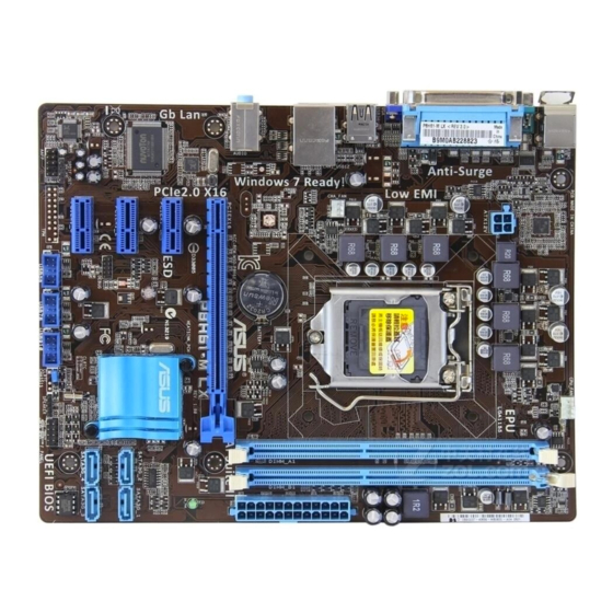
Page 18: Motherboard Layout
System panel connector (10-1 pin F-PANEL) Speaker connector (4-pin SPEAKER) Clear RTC RAM (3-pin CLRTC) USB connectors (10-1 pin USB56, USB78) Digital audio connector (4-1 pin SPDIF_OUT) Front panel audio connector (10-1 pin AAFP) ASUS P8H61-M LX R2.0 Page 1-25 1-22 1-19 1-23... -
Page 19: Central Processing Unit (Cpu)
Contact your retailer immediately if the PnP cap is missing, or if you see any damage to the PnP cap/socket contacts/motherboard components. ASUS will shoulder the cost of repair only if the damage is shipment/ transit-related. -
Page 20: Installing The Cpu
PnP cap unless you are installing a CPU. Lift the load lever in the direction of the arrow until the load plate is completely lifted. 1-10 Load lever Retention tab Load plate ASUS P8H61-M LX R2.0... - Page 21 Remove the PnP cap from the CPU socket by lifting the tab only. Position the CPU over the socket, ensuring that the gold triangle is on the bottom-left corner of the socket, and then fit the socket alignment keys into the CPU notches.
- Page 22 Close the load plate (A), and then push down the load lever (B), ensuring that the front edge of the load plate slides under the retention knob (C). Insert the load lever under the retention tab. 1-12 ASUS P8H61-M LX R2.0...
-
Page 23: Installing The Cpu Heatsink And Fan
1.6.2 Installing the CPU heatsink and fan The Intel LGA1155 processor requires a specially designed heatsink and fan assembly to ® ensure optimum thermal condition and performance. • When you buy a boxed Intel heatsink assembly. If you buy a CPU separately, ensure that you use only Intel multi-directional heatsink and fan. -
Page 24: Uninstalling The Cpu Heatsink And Fan
Disconnect the CPU fan cable from the connector on the motherboard. Rotate each fastener counterclockwise. Pull up two fasteners at a time in a diagonal sequence to disengage the heatsink and fan assembly from the motherboard. 1-14 CPU_FAN ASUS P8H61-M LX R2.0... -
Page 25: System Memory
Carefully remove the heatsink and fan assembly from the motherboard. Rotate each fastener clockwise to ensure correct orientation when reinstalling. System memory 1.7.1 Overview The motherboard comes with two Double Data Rate 3 (DDR3) Dual Inline Memory Modules (DIMM) sockets. A DDR3 module has the same physical dimensions as a DDR2 DIMM but is notched differently to prevent installation on a DDR2 DIMM socket. -
Page 26: Memory Configurations
• For system stability, use a more efficient memory cooling system to support a full memory load (2 DIMMs) or overclocking condition. Visit the ASUS website at www.asus.com for the latest QVL. 1-16 ® OS when you want to install 4GB or more on the ®... - Page 27 P8H61-M LX R2.0 Series Motherboard Qualified Vendors Lists (QVL) DDR3-2400 MHz capability Vendors Part No. CORSAIR CMGTX8(XMP) G.SKILL F3-19200CL11Q-16GBZHD(XMP1.3) G.SKILL F3-19200CL9D-4GBPIS(XMP) GEIL GET34GB2400C9DC(XMP) KINGMAX FLLE88F-C8KKAA HAIS(XMP) Transcend TX2400KLU-4GK(427652)(XMP) Transcend TX2400KLU-4GK (381850)(XMP) Transcend TX2400KLU-4GK(374243)(XMP) PATRIOT PVV34G2400C9K(XMP) • DDR3 1600 MHz and higher memory frequency is supported by Intel processors.
- Page 28 1.65V • • 9-9-9-24 1.65V • • 9-10-9-27 1.50V • • 9-10-9-28 1.5V • • 10-11-10-30 1.5V • • 9-10-9-28 1.5V • • 9-9-9-24 1.6V • • 1.65V • • 1.65V • • 1.65V • • ASUS P8H61-M LX R2.0...
- Page 29 DDR3-1600 MHz capability Vendors Part No. A-DATA AM2U16BC2P1 A-DATA AM2U16BC4P2 A-DATA AX3U1600GC4G9-2G(XMP) A-DATA AX3U1600XC4G79-2X(XMP) CORSAIR CMD12GX3M6A1600C8(XMP) 12GB(6x2GB) CORSAIR CMP4GX3M2A1600C8(XMP) CORSAIR CMP4GX3M2A1600C9(XMP) CORSAIR CMP4GX3M2C1600C7(XMP) CORSAIR CMX4GX3M2A1600C9(XMP) CORSAIR CMX4GX3M2A1600C9(XMP) CORSAIR TR3X6G1600C8 G(XMP) CORSAIR TR3X6G1600C8D G(XMP) CORSAIR TR3X6G1600C9 G(XMP) CORSAIR CMP8GX3M2A1600C9(XMP) CORSAIR CMX8GX3M4A1600C9(XMP) Crucial BL25664BN1608.16FF(XMP) G.SKILL...
- Page 30 • • • • 9-9-9-20 1.65V • • 9-9-9-20 1.7V • • 9-9-9-20 1.7V • • 9-9-9-20 1.65V • • 7-7-7-20 1.65V • • 7-7-7-20 1.75V • • 9-9-9-20 1.65V • • 7-7-7-20 1.65V • • ASUS P8H61-M LX R2.0...
- Page 31 DDR3-1333 MHz capability Vendors Part No. Size OCZ3X1333LV6GK(XMP) 6GB(3 x 2GB) DS - OCZ3G1333LV8GK 8GB(2x 4GB) OCZ3RPR1333C9LV8GK 8GB(2x 4GB) AL7F8G73D-DG1 AL7F8G73F-DJ2 AL8F8G73D-DG1 AL8F8G73F-DJ2 SAMSUNG M378B2873FHS-CH9 SAMSUNG M378B5673FH0-CH9 SAMSUNG M378B5273CH0-CH9 Super Talent W1333UA1GH Super Talent W1333UB2GS Super Talent W1333UB4GS Super Talent W1333UX6GM 6GB(3x 2GB) Elixir M2F2G64CB88B7N-CG...
- Page 32 • 1 DIMM: Supports one module inserted into either slot as single-channel memory • 2 DIMMs: Supports one pair of modules inserted into both the blue slots as one pair of Visit the ASUS website at www.asus.com for the latest QVL. 1-22 Size Chip Brand Chip NO.
-
Page 33: Installing A Dimm
1.7.3 Installing a DIMM Unplug the power supply before adding or removing DIMMs or other system components. Failure to do so can cause severe damage to both the motherboard and the components. Press the retaining clips outward to unlock a DIMM socket. Align a DIMM on the socket such that the notch on the DIMM matches the DIMM slot key on... -
Page 34: Expansion Slots
PCI Express specifications. 1.8.4 PCI Express 3.0/2.0 x16 slot This motherboard has a PCI Express 3.0/2.0 x16 slot that supports PCI Express 3.0/2.0 x16 graphic cards complying with the PCI Express specifications. 1-24 ASUS P8H61-M LX R2.0... -
Page 35: Jumpers
Jumpers Clear RTC RAM (3-pin CLRTC) This jumper allows you to clear the Real Time Clock (RTC) RAM in CMOS. You can clear the CMOS memory of date, time, and system setup parameters by erasing the CMOS RTC RAM data. The onboard cell battery powers the RAM data in CMOS, which include system setup information such as system passwords. -
Page 36: Connectors
Line Out Front Speaker Out Mic In Mic In – – Speed Activity Link LAN port 6-channel 8-channel Rear Speaker Out Rear Speaker Out Front Speaker Out Front Speaker Out Bass/Center Bass/Center – Side Speaker Out ASUS P8H61-M LX R2.0... -
Page 37: Internal Connectors
Use a chassis with an HD audio module in the front panel to support 8-channel audio output. USB 2.0 ports 1 and 2. These two 4-pin Universal Serial Bus (USB) ports are for USB 2.0/1.1 devices. USB 2.0 ports 3 and 4. These two 4-pin Universal Serial Bus (USB) ports are for USB 2.0/1.1 devices. - Page 38 The system may become unstable or may not boot up if the power is inadequate. • If you are uncertain about the minimum power supply requirement for your system, refer to the Recommended Power Supply Wattage Calculator at http://support.asus. com/PowerSupplyCalculator/PSCalculator.aspx?SLanguage=en-us for details. Speaker connector (4-pin SPEAKER) The 4-pin connector is for the chassis-mounted system warning speaker.
-
Page 39: Cpu And Chassis Fan Connectors
• The CPU_FAN connector supports a CPU fan of maximum 2A (24 W) fan power. • Only the 4-pin CPU fan supports ASUS FanXpert feature. USB connectors (10-1 pin USB56, USB78) These connectors are for USB 2.0 ports. Connect the USB module cable to any of these connectors, then install the module to a slot opening at the back of the system chassis. - Page 40 XP Service Pack 3 or a later version before using Serial ATA ® ® XP, there is no need to change the ® Vista / Windows ® SPDIF_OUT Vista / Windows ® ® 7, set the SATA Mode ® ASUS P8H61-M LX R2.0...
-
Page 41: System Panel Connector (10-1 Pin Panel)
System panel connector (10-1 pin PANEL) This connector supports several chassis-mounted functions. P8H61-M LX R2.0 P8H61-M LX R2.0 System panel connector • System power LED (2-pin PLED) This 2-pin connector is for the system power LED. Connect the chassis power LED cable to this connector. -
Page 42: Software Support
The contents of the Support DVD are subject to change at any time without notice. Visit the ASUS website at www.asus.com for updates. To run the Support DVD Place the Support DVD into the optical drive. If Autorun is enabled in your computer, the DVD automatically launches the main setup screen. -
Page 43: Chapter 2 Bios Information
BIOS in the future. Copy the original motherboard BIOS using the ASUS Update utility. 2.1.1 ASUS Update utility The ASUS Update is a utility that allows you to manage, save, and update the motherboard BIOS in a Windows environment. ®... -
Page 44: Asus Ez Flash 2
Follow the onscreen instructions to complete the updating process. 2.1.2 ASUS EZ Flash 2 The ASUS EZ Flash 2 feature allows you to update the BIOS without using an OS-based utility. Before you start using this utility, download the latest BIOS file from the ASUS website at www.asus.com. -
Page 45: Asus Crashfree Bios 3 Utility
2.1.3 ASUS CrashFree BIOS 3 utility The ASUS CrashFree BIOS 3 is an auto recovery tool that allows you to restore the BIOS file when it fails or gets corrupted during the updating process. You can restore a corrupted BIOS file using the motherboard support DVD or a USB flash drive that contains the updated BIOS file. -
Page 46: Asus Bios Updater
2.1.4 ASUS BIOS Updater The ASUS BIOS Updater allows you to update the BIOS in a DOS environment. This utility also allows you to copy the current BIOS file as a backup when the BIOS fails or gets corrupted during the updating process. -
Page 47: Updating The Bios File
Updating the BIOS file To update the BIOS file using BIOS Updater At the FreeDOS prompt, type bupdater /pc /g and press <Enter>. D:\>bupdater /pc /g The BIOS Updater screen appears as below. ASUSTek BIOS Updater for DOS V1.18 Current ROM BOARD: P8H61-M LX R2.0 VER:... -
Page 48: Bios Setup Program
• The BIOS setup screens shown in this section are for reference purposes only, and may not exactly match what you see on your screen. • Visit the ASUS website at www.asus.com to download the latest BIOS file for this motherboard. -
Page 49: Bios Menu Screen
BIOS menu screen The BIOS setup program can be used under two modes: EZ Mode and Advanced Mode. You can change modes by pressing F7 or through the Exit/Advanced Mode button in the EZ Mode/Advanced Mode screen. EZ Mode By default, the EZ Mode screen appears when you enter the BIOS setup program. The EZ Mode provides you an overview of the basic system information, and allows you to select the display language, system performance mode and boot device priority. -
Page 50: Advanced Mode
The Advanced Mode provides advanced options for experienced end-users to configure the BIOS settings. The figure below shows an example of the Advanced Mode. Refer to the following sections for the detailed configurations. To access the EZ Mode, click Exit, then select ASUS EZ Mode. Back button Menu items... -
Page 51: Menu Items
Menu items The highlighted item on the menu bar displays the specific items for that menu. For example, selecting Main shows the Main menu items. The other items (Ai Tweaker, Advanced, Monitor, Boot, Tool, and Exit) on the menu bar have their respective menu items. -
Page 52: Main Menu
RAM to clear the BIOS password. See section 1.9 Jumpers for information on how to erase the RTC RAM. • The Administrator or User Password items on top of the screen show the default Not Installed. After you set a password, these items show Installed. 2-10 ASUS P8H61-M LX R2.0... -
Page 53: Administrator Password
Administrator Password If you have set an administrator password, we recommend that you enter the administrator password for accessing the system. Otherwise, you might be able to see or change only selected fields in the BIOS setup program. To set an administrator password: Select Security and press <Enter>. - Page 54 To clear the user password, follow the same steps as in changing a user password, but press <Enter> when prompted to create/confirm the password. After you clear the password, the User Password item on top of the screen shows Not Installed. 2-12 ASUS P8H61-M LX R2.0...
-
Page 55: Ai Tweaker Menu
Ai Tweaker menu The Ai Tweaker menu items allow you to configure overclocking-related items. Be cautious when changing the settings of the Ai Tweaker menu items. Incorrect field values can cause the system to malfunction. The configuration options for this section vary depending on the CPU and DIMM model you installed on the motherboard. -
Page 56: Memory Frequency [Auto]
Allows processor cores to run faster than marked frequency in specific conditions. Disables this function. SpeedStep Technology (EIST). ® SpeedStep Technology item ® ASUS P8H61-M LX R2.0... -
Page 57: Digi+ Vrm
The following three items appear only when you set both the Enhanced Intel Technology and Turbo Mode items to [Enabled]. Long Duration Power Limit [Auto] Use <+>/<-> to adjust the value. Long Duration Maintained [Auto] Use <+>/<-> to adjust the value. Short Duration Power Limit [Auto] Use <+>/<->... - Page 58 Allows you to set the iGPU Current Capability. Configuration options: [100%] [110%] [120%] [130%] [140%] Do not remove the thermal module while changing the DIGI+ VRM related parrameters . The thermal conditions should be monitored. 2-16 ASUS P8H61-M LX R2.0...
-
Page 59: Cpu Voltage [Offset Mode]
2.4.7 CPU Voltage [Offset Mode] [Manual Mode] Allows you to set a fixed CPU voltage. [Offset Mode] Allows you to set the Offset voltage. 2.4.8 Offset Mode Sign [+] This item appears only when you set the CPU Voltage item to [Offset Mode]. To offset the voltage by a positive value. -
Page 60: Cpu Pll Voltage [Auto]
2.5.1 CPU Configuration The items in this menu show the CPU-related information that the BIOS automatically detects. The items shown in submenu may be different due to the CPU you installed. 2-18 ASUS P8H61-M LX R2.0... - Page 61 CPU Ratio [Auto] Allows you to set the ratio between the CPU Core Clock and the BCLK Frequency. Use <+> and <-> keys or the numeric keypad to adjust the ratio. The valid value ranges vary according to your CPU model. Intel Adaptive Thermal Monitor [Enabled] [Enabled] Enables the overheated CPU to throttle its clock speed to cool down.
-
Page 62: Pch Configuration
[Disabled] Disables this function. 2.5.2 PCH Configuration High Precision Timer [Enabled] Allows you to enable or disable the High Precision Event Timer. Configuration options: [Enabled] [Disabled] 2-20 ASUS P8H61-M LX R2.0... -
Page 63: Sata Configuration
2.5.3 SATA Configuration While entering Setup, the BIOS automatically detects the presence of SATA devices. The SATA Port items show Not Present if no SATA device is installed to the corresponding SATA port. SATA Mode Selection [IDE Mode] Allows you to set the SATA configuration. [Disabled] Disables the SATA function. -
Page 64: System Agent Configuration
Allows you to enable or disable Render Standby by internal graphics devices. Configuration options: [Disabled] [Enabled] IGPU Multi-Monitor Allows you to enable or disable Internal Graphics Device Multi-Monitor Support for add- on VGA devices. Configuration options: [Disabled] [Enabled] 2-22 ASUS P8H61-M LX R2.0... -
Page 65: Usb Configuration
2.5.5 USB Configuration The items in this menu allow you to change the USB-related features. The USB Devices item shows the auto-detected values. If no USB device is detected, the item shows None. Legacy USB Support [Enabled] [Enabled] Enables the support for USB devices on legacy operating systems (OS). [Disabled] The USB devices can be used only for the BIOS setup program. -
Page 66: Serial Port Configuration
The system goes into on state after an AC power loss. [Power Off] The system goes into off state after an AC power loss. [Last State] The system goes into either off or on state, whatever the system state was before the AC power loss. 2-24 ASUS P8H61-M LX R2.0... -
Page 67: Network Stack
Power On By PS/2 Keyboard [Disabled] [Disabled] Disables the Power On by a PS/2 keyboard. [Space Bar] Sets the Space Bar on the PS/2 keyboard to turn on the system. [Ctrl-Esc] Sets the Ctrl+Esc key on the PS/2 keyboard to turn on the system. [Power Key] Sets Power key on the PS/2 keyboard to turn on the system. -
Page 68: Monitor Menu
(RPM). If the fan is not connected to the motherboard, the field shows N/A. Select Ignore if you do not wish to display the detected speed. 2.6.3 CPU Q-Fan Control [Enabled] [Disabled] Disables the CPU Q-Fan control feature. [Enabled] Enables the CPU Q-Fan control feature. 2-26 [xxx�C/xxx�F] ASUS P8H61-M LX R2.0... -
Page 69: Cpu Fan Speed Low Limit [200 Rpm]
2.6.4 CPU Fan Speed Low Limit [200 RPM] This item appears only when you enable the CPU Q-Fan Control feature and allows you to disable or set the CPU fan warning speed. Configuration options: [Ignore] [200 RPM] [300 RPM] [400 RPM] [500 RPM] [600 RPM] CPU Fan Profile [Standard] This item appears only when you enable the CPU Q-Fan Control feature and allows you to set the appropriate performance level of the CPU fan. -
Page 70: Boot Menu
[Disabled] Disables the full screen logo display feature. Set this item to [Enabled] to use the ASUS MyLogo 2™ feature. Post Report [5 sec] This item appears only when the Full Screen Logo item is set to [Disabled] and allows you to set the waiting time for the system to display the post report. -
Page 71: Option Rom Messages [Force Bios]
• To select the boot device during system startup, press <F8> when ASUS Logo appears. • To access Windows OS in Safe Mode, press <F8> after POST. -
Page 72: Tools Menu
<Enter> to display the submenu. 2.8.1 ASUS EZ Flash Utility Allows you to run ASUS EZ Flash 2. Press [Enter] to launch the ASUS EZ Flash 2 screen. For more details, see section 2.1.2 ASUS EZ Flash 2. 2.8.2... -
Page 73: Exit Menu
This option allows you to exit the Setup program without saving your changes. When you select this option or if you press <Esc>, a confirmation window appears. Select Yes to discard changes and exit. ASUS EZ Mode This option allows you to enter the EZ Mode screen. Launch EFI Shell from filesystem device This option allows you to attempt to launch the EFI Shell application (shellx64.efi) from one of... - Page 74 2-32 ASUS P8H61-M LX R2.0...
-
Page 75: Appendices
Appendices Notices Federal Communications Commission Statement This device complies with Part 15 of the FCC Rules. Operation is subject to the following two conditions: • This device may not cause harmful interference. • This device must accept any interference received including interference that may cause undesired operation. -
Page 76: Canadian Department Of Communications Statement
ASUS Recycling/Takeback Services ASUS recycling and takeback programs come from our commitment to the highest standards for protecting our environment. We believe in providing solutions for you to be able to responsibly recycle our products, batteries, other components as well as the packaging materials. Please go to http://csr.asus.com/english/Takeback.htm for the detailed recycling information in different... -
Page 77: Asus Contact Information
ASUS COMPUTER INTERNATIONAL (America) Address Telephone Web site Technical Support Telephone Support fax Online support ASUS COMPUTER GmbH (Germany and Austria) Address Web site Online contact Technical Support Telephone Support Fax Online support * EUR 0.14/minute from a German fixed landline; EUR 0.42/minute from a mobile phone. - Page 78 ASUS P8H61-M LX R2.0...