Table of Contents
Advertisement
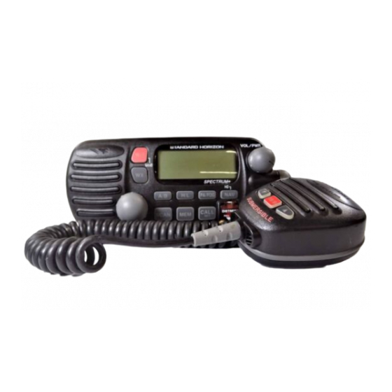
Submersible
DSC distress call automatically broadcasts lat/long and vessel ID ∗
MARITEL DSC telephone capability
DSC position request function and NMEA data input/output
Noise canceling Clear Voice Speaker microphone with channel selector
20 W Loud Hailer with Bells & Whistles
Latitude/Longitude and SOG/COG display ∗
Channel name capability
Versatile user-programmable scanning and priority scan
NOAA Weather Alert
One-button access to Channel 16 and 9
Access all US, Canadian and International channels
Big, back-lit display and keys
∗ with GPS attached
SPECTRUM + GX2355S
25 Watt VHF/FM
Marine Transceiver
Owner ' s Manual
16/9
Advertisement
Table of Contents

Related Manuals for Standard Horizon SPECTRUM + GX2355S


Summary of Contents for Standard Horizon SPECTRUM + GX2355S
- Page 1 Versatile user-programmable scanning and priority scan NOAA Weather Alert One-button access to Channel 16 and 9 Access all US, Canadian and International channels Big, back-lit display and keys ∗ with GPS attached SPECTRUM + GX2355S 25 Watt VHF/FM Marine Transceiver Owner ' s Manual 16/9...
-
Page 2: Table Of Contents
TABLE OF CONTENTS FCC RADIO LICENSE INFORMATION ... 1 STATION LICENSE ... 1 RADIO CALL SIGN ... 1 CANADIAN SHIP STATION LICENSING ... 1 FCC NOTICE ... 2 GENERAL INFORMATION ... 3 1.1 INTRODUCTION ... 3 1.2 FCC/ INDUSTRY CANADA INFORMATION .. 3 ACCESSORIES ... - Page 3 6.12 RECEIVING DSC CALLS ... 34 6.12.1 Receiving a distress call ... 34 6.12.2 Receiving a distress relay call ... 35 6.12.3 Receiving an all ships call ... 35 6.12.4 Receiving a geographical area call .. 35 6.12.5 Receiving an individual call ... 36 6.12.6.
-
Page 4: Fcc Radio License Information
STANDARD HORIZON Web site. PRODUCT SUPPORT INQUIRIES If you have any questions or comments regarding the use of the SPECTRUM+, you can visit the STANDARD HORIZON Web site to send an E-Mail or contact the Product Support team at 562/404-2700 M-F 7:00-5:00PST. -
Page 5: Fcc Notice
Unauthorized changes or modifications to this equipment may void compliance with FCC Rules. Any change or modification must be approved in writing by STANDARD HORIZON. This equipment has been tested and found to comply with the limits for a Class B digital device, pursuant to Part 15 of the FCC Rules. These limits are designed to provide reasonable protection against harmful interference in a residential installation. -
Page 6: General Information
1.1 INTRODUCTION The STANDARD HORIZON GX2355S is a VHF/FM transceiver designed for use in the frequency range of 156.025 to 163.275 MHz. The GX2355S requires 13.8V for operation and has a switchable RF output power of 1 watt or 25 watts. -
Page 7: Accessories
2.1 PACKING LIST When the package containing the transceiver is first opened, please check it for the following contents: • GX2355S SPECTRUM + Transceiver (White/Black) • CMP351W/CMP351B (White/Black Microphone attached to the transceiver) and hanger kit • Mounting Bracket and attaching hardware •... -
Page 8: Controls And Indicators
Immediately recalls channel 16 from any channel location. Holding down this key recalls channel 9. Pressing the 16/9 key again reverts to the previous selected working channel. Secondary use Please see secondary use for the WX and MEM key. GX2355S NOTE NOTE Owner’s Manual page 5... - Page 9 VOL / PWR 16 9 U I C SPECTRUM+ A / B H / L PA/FOG CALL SCAN DISTRESS PULL OPEN MENU PA VOL 16/9 Figure 1. Controls and Connectors page 6 Owner’s Manual GX2355S...
- Page 10 If position is displayed, this icon will be hidden. DISTRESS Key To send the distress call see section 6.2, (Sending a Distress Call). PA/FOG key Available to operate the PA function or the FOG HORN function GX2355S NOTE NOTE NOTE Owner’s Manual...
- Page 11 While holding down the SCAN Key and turning the Channel Selector knob, you can confirm memory channels for scanning. t RAM MIC CONNECTOR Connects the Remote Access Microphone (RAM MIC). Refer to “section 8.0, (RAM MIC OPERATION). page 8 Owner’s Manual GX2355S...
-
Page 12: Microphone Speaker
16/9 key again reverts the radio to the previous select channel. !3 MICROPHONE SPEAKER The same audio heard through internal radio speaker as heard through microphone speaker. GX2355S KEYS on the mic function the same as the Channel Owner’s Manual... -
Page 13: Installation
RG-8/U coaxial cable must be used if the antenna is 25 feet or more from the radio. RG58 cable can be used for distances less than 25 feet. page 10 INSTALLATION CAUTION Optional Speaker Accessory cable Fuse 16/9 Black Owner’s Manual GPS Navigation Receiver GX2355S... -
Page 14: Accessory Cable
Never short wires. This may lead to malfunctions. To GX2355S To external speaker, PA speaker and GPS receiver ∗ 1: Connecting these wires to Standard Horizon GPS to show a DSC Position Request, Position Send or Distress Call on the display of the GPS. GX2355S Signal NMEA 0183 Version (1.5 to 2.3 ) Input Sentences:... -
Page 15: Cmb16 Flush Mount Installation
(see Figure 3). 5. Turn the adjusting screw to adjust the tension so that the transceiver is tight against the mounting surface. Figure 3. CMB16 Flush Mount Installation page 12 Bracket Lock-washer nut combination Owner’s Manual adjusting screw GX2355S... -
Page 16: Basic Operation
This is a noise-canceling microphone. The oval slot on the top front of microphone should be positioned within 1 inch (2 cm) from the mouth for optimum performance. 6. Refer to the section 9 OPERATING PRACTICES for standard transceiver operating procedures. GX2355S BASIC OPERATION NOTE Owner’s Manual page 13... -
Page 17: Transmit Time - Out Timer (Tot)
2. USA will be displayed on the LCD for USA mode, INTL will be displayed for International mode, and CAN will be displayed for Canadian mode. 3. Refer to the channel chart (section 11 CHANNEL ASSIGNMENTS) for allocated channels in each mode. page 14 NOTE Owner’s Manual GX2355S... -
Page 18: Noaa Weather Channels
5. Press the WX key to stop the alert tone and receive the weather report. If the WX key is not pressed the alert tone will be emitted for 5 minutes and then the weather report will be received. GX2355S NOTE Owner’s Manual page 15... -
Page 19: Memory Scanning (M-Scan)
Scanning will proceed between the memorized channels and the priority channel. The priority channel will be scanned after each programmed channel. CH. 70 MEM CH. (When DSC scaning is available) Owner’s Manual P-CH. CH. 70 (When DSC scaning is available) GX2355S... -
Page 20: Channel A /B Instant Call
PA HAIL mode allows the transceiver to be used as a power hailer when an optional 4 ohm hailer speaker is installed. The Hail mode has a listen-back feature which provides two way communication through the hailer speaker. GX2355S 3. The scanning will be performed while receiving the MEM CH (memorized channel). -
Page 21: Operating The Pa Hail Mode
4. On the SIREN and FOG HORN modes, press the PTT switch to activate the tone through the PA speaker. Turn the Channel Selector knob to control the AF output level. The AF output level can be set from 0 to 20 watts. Owner’s Manual GX2355S... -
Page 22: Navigation Indication
COMMERCIAL HI USA COMMERCIAL HI USA VS OFF COMMERCIAL GX2355S 1. Press the NAV key to display position information. If the GPS receiver receives no signal, the display will be as shown in the illustration on the left. 2. To hide the position information, press the NAV key. -
Page 23: Resetting The Transceiver'smicroprocessor
• WX channel 01 will be recalled when the WX key is pressed. • Key beep will be on. • No channels will be stored in the A/B memory. Resetting the microprocessor will not erase DSC MMSI and Directory Call Waiting information. page 20 NOTE Owner’s Manual GX2355S... -
Page 24: Digital Selective Calling
Maritime Mobile Service Identity (MMSI) What is an MMSI? An MMSI is a nine digit number used on Marine Transceiver capable of using Digital Selective Calling (DSC). This number is used like a telephone number to selectively call other vessels. Refer to section 7.7 (USER MMSI INPUT). -
Page 25: Sending A Distress Call
After the message has been sent, the Distress Alarm will sound. 6. The transceiver “shadow-watches” for a transmission between CH16 and CH70 until an acknowledgment signal is received. “DISTRESS” and “WAITING” will appear on the LCD. Owner’s Manual GX2355S... -
Page 26: Sending A Distress Call And Manually Inputting A Position
LCD. 5. Perform steps 5 through 10 of 6.2.1 Sending a Distress Call Automatically. GX2355S 8. To cancel a Distress Call, press the 16/9 key, turn the Channel Selector knob to select CANCEL. Then, press the CALL/SET key or turn off the radio. -
Page 27: Sending A Distress Call With Nature Of Distress
The dot-matrix area of LCD will be as shown in the illustration on the left. 5. After a message has been sent, the transceiver “DSC SCAN” between CH16 and CH70 until an acknowledgment is received. (Example: Fire is sent.) Owner’s Manual GX2355S... -
Page 28: Sending An Individual Call
DICK INDIVIDUAL WAITING NO REPLY >SEND EXIT HI USA GX2355S 1. Select the traffic channel for voice communica- tion. 2. Press the CALL/SET key. The DSC CALLING menu will appear. 3. Turn the Channel Selector knob to select INDIVIDUAL. (To cancel, select EXIT with the Channel Selector knob or press the 16/9 key.) -
Page 29: Sending A Group Call
When the Group Call signal is sent, the dot- matrix area of the LCD will be as shown in the illustration on the left. 7. After the GROUP CALL is transmitted, all the radios in the group will switch to the designated channel. Owner’s Manual GX2355S... -
Page 30: Sending An All Ships Call
WAITING HI USA DISTRESS GX2355S 1. S e l e c t t h e t r a f f i c c h a n n e l ( f o r v o i c e communication). 2. Press the CALL/SET key. The DSC CALLING menu will appear. -
Page 31: Maritel Dsc Telephone Call
If no elapsed time data is received, “– – : – – : – –” will be shown. Owner’s Manual GX2355S... -
Page 32: Receiving A Shore To Ship Call
2. Turn the Channel Selector knob to select SEND. To exit the telephone call, turn the Channel Selector knob to select EXIT and press the CALL/SET key. GX2355S 1. When the transceiver receives the telephone call starting signal from the shore, the alarm will sound. -
Page 33: Dsc Standby
When a DISTRESS CALL is received, this call will be logged on the distress call waiting directory. page 30 1. Press the CALL/SET key. The DSC CALLING menu will appear. 2. Turn the Channel Selector knob to select the STANDBY mode. 3. Press the CALL/SET key. NOTE NOTE Owner’s Manual GX2355S... -
Page 34: Operation Of Distress Call Waiting
INDIVIDUAL EXIT CALL WAIT DISTRESS >INDIVIDUAL EXIT GX2355S 1. Press the CALL/SET key. The DSC CALLING menu will appear. 2. Turn the Channel Selector knob to select CALL WAIT. 3. Press the CALL/SET key. 4. Turn the Channel Selector knob to select DISTRESS. -
Page 35: Position Request
This directory uses the INDIVIDUAL Directory information. 4. Turn the Channel Selector knob or press the UP/ DOWN keys on the microphone to select a name. 5. Press the CALL/SET key to transmit the position request DSC call. Owner’s Manual GX2355S... -
Page 36: Position Send
10. When the transceiver receives the requested position, the transceiver outputs a NMEA DSC sentence which may be used by a Standard Horizon GPS chart plotter to show the vessels position. 6.11 POSITION SEND The position send mode may be used to send your position to another radio with this feature. -
Page 37: Receiving Dsc Calls
Then channel 16 is automatically selected. 2. Press any key to stop the alarm. 3. If the received distress data does not include the position data, the LCD will show the display on the left. NOTE Owner’s Manual GX2355S... -
Page 38: Receiving A Distress Relay Call
2. Press any key to stop the alarm. 3. Monitor the traffic channel for an announcement from the calling ship. This feature is only available when a GPS receiver is connected. GX2355S 1. A distress relay call is received. An emergency alarm sounds. -
Page 39: Receiving An Individual Call
1. When a position request call is received, the LCD will be as shown in the illustration on the left. 2. A calling alarm sounds 4 times. Then select type of reply function REPLY or EXIT by using the Channel Selector knob. Owner’s Manual GX2355S... -
Page 40: Dsc / Radio Setup Mode
7.3 LCD CONTRAST LANP ADJUST >CONTRAST CH NAME INDIV DIR CONTRAST GX2355S DSC / RADIO SETUP MODE 1. Press and hold down the CALL/SET key until the SETUP menu appears. 2. To select the items, turn the Channel Selector knob. -
Page 41: Ch Naming
H/L key. 8. If you want to enter the name of another channel, select NEXT and press the CALL/SET key. Repeat steps 2 through 6. To return the Setup menu, select the EXIT and press the CALL/SET key. Owner’s Manual GX2355S... -
Page 42: Individual Directory Setup (Dsc)
CALL/SET key. Repeat procedure until all nine space of MMSI number are entered. GX2355S 1. Press and hold the CALL/SET key until the SETUP menu is displayed. -
Page 43: Dsc Telephone Directory Id Input
16 digits. The display will show up to 12 digits, when you enter 13 digits or more, the arrow symbol will appear. Press and hold the CALL/SET key to store the telephone number. Owner’s Manual GX2355S... -
Page 44: Position Request Reply Type
To send your position, you will have to press the CALL/SET key. 5. Press the CALL/SET key to store a selected reply type. The LCD display will return to the SETUP menu. GX2355S 7. Press and hold the CALL/SET key until Coast MMSI is displayed. -
Page 45: Voice Scrambler
10. Press and hold down the CALL/SET key to exit from the channel select menu. The LCD will return to the SCRAMBLER SETUP menu. 11. Select ON to use the scrambler operation and press the CALL/SET key. The LCD will return to the SETUP menu. NOTE Owner’s Manual GX2355S... -
Page 46: Key Beep (On Or Off)
INDIVIDUAL CALL. DEFAULT setting rings for 3 minutes continuously. 5. Press the CALL/SET key to store the INDIV RING. The LCD will return to the SETUP menu. GX2355S 2. Select KEY BEEP in the SETUP menu with the Channel Selector knob. 3. Press the CALL/SET key. -
Page 47: Time Offset
( U n i v e r s a l T i m e C o o r d i n a t e d o r G M T Greenwich Mean Time) 0 +1 +2 +3 +4 +5 +6 +7 +8 +9 +10 +11 +12 UTC/GMT Figure 4. Offset time table Owner’s Manual GX2355S... -
Page 48: User Mmsi Input
MMSI more than twice, the transceiver will have to be sent to Factory Service. Refer to the section 10.2 FACTORY SERVICE. GX2355S 2. Select the USER MMSI in the SETUP menu with the Channel Selector knob. 3. Press the CALL/SET key. -
Page 49: Group Mmsi Input
(0 to 9 ). 5. Press the CALL/SET key to store the set number. The blinking number is stored, and the next space will blink. 6. Repeat steps 3 and 4 to set your GROUP MMSI. Owner’s Manual GX2355S... -
Page 50: Dsc Scanning
4. Turn the Channel Selector knob to select ON or OFF. 5. To store the selection, press the CALL/SET key. The LCD will return to the SETUP menu. GX2355S 2. Select DSC SCAN using the Channel Selector knob. 3. Press the CALL/SET key. The DSC SCAN setting menu will appear. -
Page 51: Ram Mic Operation
16/9 key to recall channel 9. Recalls the previous channel when the 16/9 key is pressed again. When holding down the 16/9 key while pressing the WX key, the mode toggles between USA, International and Canadian. page 48 RAM MIC OPERATION Owner’s Manual GX2355S... - Page 52 MEM key until the MEM disappears from the LCD. If the transceiver is in the M-SCAN mode, then the RAM Mic is in SC mode. If the transceiver is in P-SCAN mode, then the RAM Mic is in PS mode. GX2355S SCAN Figure 5. CMP23 RAM Mic NOTE Owner’s Manual...
-
Page 53: Indicators
“TX” is displayed in transmitting mode. “BUSY” is displayed in receiving mode. USA/ INTL/ CAN Indicator The mode of operation. “USA” indicates USA mode. “INTL” indicates International mode and “CAN” indicates Canadian mode. WX Indicator A weather channel. page 50 Owner’s Manual GX2355S... -
Page 54: Intercom Operation
5. When finished, release the PTT switch. 8.3.2 Calling 1. Hold down the IC key in the intercom operation for 1 second or more. A calling beep is emitted twice from the transceiver speaker. GX2355S EXTERNAL SPEAKER NOTE: If the RAM Mic is connected to... -
Page 55: Operating Practices
U.S. waters by using channel 9 as the initial contact (hailing) channel for non-emergency communications. Here, also, calling time should not exceed 30 seconds but may be repeated 3 times at 2-minute intervals. page 52 OPERATING PRACTICES ” (your vessel's name). ,” (your vessel’s name). Owner’s Manual GX2355S... -
Page 56: Making Telephone Calls
(telephone credit card, collect, etc.) and then link your radio transmission to the telephone lines. The marine telephone company managing the VHF channel you are using may charge a link-up fee in addition to the cost of the call. GX2355S Owner’s Manual page 53... -
Page 57: Operating On Channels 13 And 67
In order to test this system, the NOAA broadcasts the 1050 Hz tone every Wednesday, sometime between 11 AM and 1 PM. Any marine VHF radio that can detect the weather alert tone, may use this test to verify that this feature is functioning properly, page 54 Owner’s Manual GX2355S... -
Page 58: Digital Selective Calling (Dsc)
9.9.1 Distress Call Transmits a DSC Distress message to all radios equipped to receive a DSC Distress call. Some Standard Horizon radios may be connected to a GPS to also transmit the Latitude, Longitude of the vessel. 9.9.2 Individual Call This feature allows the user to contact another vessel capable of using DSC and automatically switch the radio to a desired working channel. -
Page 59: Group Call
On a fixed mount 25W radio transmission expected distances can be greater than 15 miles, for a portable 5W radio transmission the expected distance can be greater than 5 miles in “line of sight”. page 56 Owner’s Manual GX2355S... -
Page 60: Selecting An Antenna
To get your coax cable through a fitting and into your boat's interior, you may have to cut off the end plug and reattach it later. You can do this if you follow the directions that come with the connector. Be sure to make good soldered connections. GX2355S 1/16'' 3/4'' 1 1/8'' Owner’s Manual... -
Page 61: Maintenance
Mounting Bracket Knob, Black ... 444X154130 Volume Control Knob ... 443X154500 Squelch Control Knob ... 443X154500 Accessory Cable ... ZD00600090 Power Cord ... ZC01300010 Mic Hanger, White ... 277X155020 Mic Hanger, Black ... 277X155120 Dust Cover ... 03AX053010 page 58 Owner’s Manual GX2355S... -
Page 62: Factory Service
10.2 FACTORY SERVICE In the unlikely event that the radio fails to perform or needs servicing, please contact the following: Standard Horizon Factory Service 115 North Wright Brothers Drive Salt Lake City, UT 84116-2838 Telephone (800) 366-4566 Fax No. (801) 359-4122 An “RA”... -
Page 63: Troubleshooting Chart
Check the output signal format of the navigation receiver. GPS navigation receiver. This radio requires NMEA0183 format with GLL sentence as an output signal. If the GPS has a baud rate setting make sure to select 4800 and parity to NONE Owner’s Manual REMEDY GX2355S... -
Page 64: Connection Of Gps With Nmea Output
10.4 CONNECTION OF GPS WITH NMEA OUTPUT Manufacturer / Model STANDARD HORIZON CP150, CP160 and CP170C Furuno GP30, 36 Furuno GP1650, 1850 Garmin Fixed Mounts Garmin Portables JRC GPS500 JRC 100 SERIES JRC 200 SERIES Lowrance Fixed Mount Lowrance Portable... -
Page 65: Channel Assignments
The Marine Radio – Telephone User’s Handbook identifies shared channels in details. 6. Marine vessels equipped with VHF radios are required to monitor Channel 16. page 62 Owner’s Manual GX2355S... - Page 66 X X X D 157.300 161.900 Public Correspondence (Marine Operator) X X X D 157.350 161.950 Public Correspondence (Marine Operator) X X X D 157.400 162.000 Public Correspondence (Marine Operator) GX2355S VHF MARINE CHANNEL CHART CHANNEL USE Port Operation and Commercial. VTS in selected areas...
- Page 67 International: Inter-ship, Port operations and Ship movement Port Operations (inter-ship only) (1 W) Port Operations (inter-ship only) movement Non-commercial(Recreational) Commercial Commercial U.S. Government Only – Environmental protection operations. movement U.S. Government Only, Canadian Coast Guard Only U.S. Government Only, Canadian Coast Guard Only Owner’s Manual GX2355S...
- Page 68 WX10 X X X D 163.275 Weather (receive only) The BOLD channels above are not for use by the general public in US water, unless proper authorization is given. GX2355S VHF MARINE CHANNEL CHART CHANNEL USE Commercial, Inter-ship Only Owner’s Manual...
-
Page 69: Warranty
Product or part(s) therein which, upon examination by STANDARD HORIZON, appear to be defective or not up to factory specifications. STANDARD HORIZON may, at its option, repair or replace parts or subassemblies with new or reconditioned parts and subassemblies. - Page 70 This warranty only extends to Products sold within the 50 States of the United States of America and the District of Columbia. STANDARD HORIZON will pay all labor to repair the product and replacement parts charges incurred in providing the warranty service except where purchaser abuse or other qualifying exceptions exist.
- Page 71 Product Support Inquiries If you have any questions or comments regarding the use of the SPECTRUM+, you can visit the STANDARD HORIZON Web site to send an E-Mail or contact the Product Support team at 562/404-2700 M-F 7:00- 5:00PST.
-
Page 72: Specifications
20 dB Quieting ... 0.35 µV 12 dB SINAD ... 0.25 µV Squelch Sensitivity (Threshold) ... 0.13 µV Modulation Acceptance Bandwidth ... ± 7.5 kHz GX2355S SPECIFICATIONS (80 H x 176 W x 185 D mm) (51 H x 143 W x 133 D mm) characteristic at 300 to 3000 Hz Owner’s Manual... -
Page 73: Dsc
Frequency Stability (-20° to +50°C) ... ± 0.0005 % Channel Spacing ... 25 kHz 13.4 DSC DSC Format ... RTCMSC101 NMEA 0183 Input ... GLL, RMC NMEA 0183 Output ... DSC, DSE page 70 de-emphasis characteristic at 300 to 3000 Hz Owner’s Manual GX2355S... - Page 74 Marine Division of Vertex Standard US Headquarters 17210 Edwards Rd., Cerritos, CA 90703 Phone 562/404-2700 Fax 800/552/6813 Email marinetech@vxstd.com www.vxstd.com Printed in China 03/2002 03AX851010 E Y 2 8 1 N 1 0 0...