Table of Contents
Advertisement
Available languages
Available languages
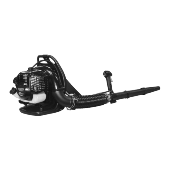
Operator's Manual
2-Cycle
GAS BACKPACK BLOWER
Model No. 316.794991
with
CAUTION: Before using this
product, read this manual and
follow all safety rules and oper-
ating instructions.
Sears, Roebuck and Co., Hoffman Estates, IL 60179, U.S.A.
Visit our website: www.sears.com/craftsman
• SAFETY
• ASSEMBLY
• OPERATION
• MAINTENANCE
• PARTS LIST
9096-320632 date(01/07)
Advertisement
Chapters
Table of Contents

Related Manuals for Craftsman 316.794991


Summary of Contents for Craftsman 316.794991
- Page 1 Operator’s Manual 2-Cycle GAS BACKPACK BLOWER Model No. 316.794991 with CAUTION: Before using this product, read this manual and follow all safety rules and oper- ating instructions. Sears, Roebuck and Co., Hoffman Estates, IL 60179, U.S.A. Visit our website: www.sears.com/craftsman •...
-
Page 2: Table Of Contents
TWO YEAR LIMITED WARRANTY ON CRAFTSMAN GAS BACKPACK BLOWER For two years from the date of purchase, when this Blower is used and maintained according to the operator’s manual, Sears will repair any defect in material or workmanship free of charge. -
Page 3: Safety Rules
The purpose of safety symbols is to attract your atten- tion to possible dangers. The safety symbols, and their explanations, deserve your careful attention and under- standing. The safety warnings do not by themselves eliminate any danger. The instructions or warnings they give are not substitutes for proper accident prevention measures. -
Page 4: While Operating
• Turn the engine off and disconnect the spark plug for maintenance of repair. • Never point the blower or blowing debris in the direc- tion of people, animals or in the direction of windows. Always direct the blowing debris away from people, animals, and windows. -
Page 5: Save These Instructions
OTHER SAFETY WARNINGS • Always disconnect the spark plug before performing maintenance or accessing movable parts. • Never store the unit, with fuel in the tank, inside a build- ing where fumes may reach an open flame (pilot lights, etc.) or sparks (switches, electrical motors, etc.). •... -
Page 6: Rules For Safe Operation
SAFETY AND INTERNATIONAL SYMBOLS This operator's manual describes safety and international symbols and pictographs that may appear on this product. Read the operator's manual for complete safety, assembly, operating and maintenance and repair information. SYMBOL MEANING • SAFETY ALERT SYMBOL Indicates danger, warning, or caution. - Page 7 KNOW YOUR BLOWER BLOWER COMPONENTS THROTTLE TRIGGER THROTTLE LOCK ON/OFF IGNITION SWITCH TOP ASSIST HANDLE SPARK PLUG WIRE / SPARK PLUG CHOKE LEVER STARTER HANDLE AIR CLEANER COVER FUEL CAP 10. FUEL TANK 11. PRIMER BULB 12. HARNESS 13. CONTROL HANDLE 14.
-
Page 8: Oil And Fuel Information
OIL AND FUEL MIXING INSTRUCTIONS Old and/or improperly mixed fuel are the main reasons for the unit not running properly. Be sure to use fresh, (less than 60 days old) clean unleaded fuel. Follow the instructions carefully for the proper fuel/oil mixture. Definition of Blended Fuels Today's fuels are often a blend of gasoline and oxy- genates such as ethanol, methanol, or MTBE (ether). -
Page 9: Assembly
Fig. 1 Fig. 2 ATTACH OPERATING TUBE NOTE: keep the throttle cable as straight as possible when connecting the blower tubes. 1. Place the unit on flat surface during assembly. Insure screw mechanism of clamp is positioned away from operator. -
Page 10: Assembly Instructions
”, and RUN “ ”. ADJUST BACK PACK HARNESS AND CONTROL HANDLE Place blower on your back by slipping arms through the shoulder straps as if you were putting on a jacket (Figure 8). Once adjustments have been made, to the straps for user comfort, remove the blower from your back and place on level ground in an upright position. -
Page 11: Stopping The Engine
IMPORTANT IDLING INFORMATION In some cases due to operating conditions (altitude, tem- perature etc.) your blower may need a slight adjustment to the idle speed. After warm up, If unit does not Idle after restarting 2 times, follow these steps to adjust idle. -
Page 12: Operation
BLOWER OPERATIONS 1. Use the blower for trees, shrubs, flower beds, and hard-to-clean areas. 2. Use the unit around buildings and for other normal cleaning procedures. 3. Use the blower around walls, overhangs, fences, and screens. WARNING: American National Standards Institute approved shielded safety glasses or face shield when operating blower. -
Page 13: Maintenance
MAINTENANCE AND REPAIR INSTRUCTIONS MAINTENANCE SCHEDULE Perform these required maintenance procedures at the fre- quency stated in the table. These procedures should also be a part of any seasonal tune-up. NOTE: Maintenance, replacement, or repair of the emission control devices and system may only be performed by a Sears or other qualified dealer. -
Page 14: Maintenance And Repair Instructions
The carburetor was pre-set at the factory for optimum performance. If further adjustments are necessary take your blower to a Sears or other qualified service dealer. able to remove fuel filter (C) from tank. Use a piece of wire (C) with a hook formed at the end to pull filter out of tank. -
Page 15: Maintenance
1. Perform all the general maintenance recommended in the Maintenance Section of your User Manual. 2. Clean exterior of engine and blower tubes. 3. Drain fuel from the fuel tank by running the unit dry or by removing the fuel cap and tipping the motor hous- ing/fuel tank over and draining oil/fuel mixture into a container with the same 2-cycle fuel mixture. -
Page 16: Troubleshooting
UNIT WON’T START OR STARTS BUT WILL NOT RUN C A U S E 1. Incorrect starting procedures 2. Incorrect carburetor mixture adjustment setting 3. Fouled spark plug 4. Empty fuel tank 5. Primer bulb was not pressed enough UNIT STARTS, BUT ENGINE HAS LOW POWER C A U S E 1. -
Page 17: Specifications
BLOWER Throttle Control ... Finger-Tip Trigger Blower Velocity ... up to 170 mph Blower Air Output ... up to 485 cfm Approximate Unit Weight (No fuel) ... 19.5 lb. Use goggles and hearing protection The U.S. Environmental Protection Agency (EPA) and the MTD LLC are pleased to explain the emission control system warranty on your 2007 small off-road engine. -
Page 18: Parts List
Parts No. Description 9295-310801 SPARK PLUG 9SGEB-05-10 SCREW 9211-320601 PLATE, SPARK SIDE 9SRCB-05-22 SCREW 9SXMBJ05-50 SCREW 9228-334503 MUFFLER ASS'Y 9014-GP0102 MUFFLER GASKET 9211-334501 MUFFLER PLATE 9017-334501 COVER, FLYWHEEL SIDE 9SGEB-04-10 SCREW 9017-334502 COVER, STARTER SIDE 9014-334507 GASKET 9292-334501F CYLINDER 9014-334501 GASKET 9189-334501 PISTON RING... - Page 19 EPA Emission Control Warranty Statement The U.S. Environmental Protection Agency (EPA) and the Sears are pleased to explain the emission control system war- ranty on your 2007 small off-road engine. In California, new small off-road engines must be designed, built and equipped to meet the State's stringent anti-smog standards.
- Page 21 PRECAUCIÓN: Antes de utilizar este producto, lea este manual y siga todas las reglas de seguridad e instrucciones de funcionamiento. Sears, Roebuck and Co., Hoffman Estates, IL 60179, U.S.A. Visite nuestra página web: www.sears.com/craftsman • SEGURIDAD • ENSAMBLAJE • FUNCIONAMIENTO • MANTENIMIENTO •...
-
Page 22: Sears, Roebuck And Co., Dept. 817Wa, Hoffman Estates, Il
Instrucciones de Arranque/Parada DOS AÑOS DE GARANTÍA LIMITADA SOBRE EL SOPLADOR DE MOCHILA A GASOLINA CRAFTSMAN Durante dos años desde la fecha de compra, siempre que se utilice y mantenga este Soplador según el manual del usuario, Sears reparará cualquier defecto de materiales o mano de obra sin ningún cargo. -
Page 23: Reglas De Seguridad Páginas
REGLAS DE FUNCIONAMIENTO SEGURO El propósito de los símbolos de seguridad es atraer su atención sobre posibles peligros. Los símbolos de seguridad y su explicación merecen su atención y comprensión. Las advertencias de seguridad no elimi- nan el peligro por sí mismas. Las instrucciones o advertencias que ofrecen no son sustitutas de ninguna medida de prevención de accidentes. - Page 24 REGLAS DE FUNCIONAMIENTO SEGURO EN FUNCIONAMIENTO • Nunca arranque ni utilice la unidad en el interior de una habitación o edificio cerrado. Respirar los vapores del tubo de escape pueden causar la muerte. Opere la unidad únicamente en una zona exterior bien venti- lada.
- Page 25 REGLAS DE FUNCIONAMIENTO SEGURO OTRAS PRECAUCIONES DE SEGURIDAD • Desconecte siempre la bujía antes de llevar a cabo el mantenimiento o acceder a componentes móviles. • No guarde la unidad, con combustible en el tanque, en el interior de un edificio donde los vapores puedan alcanzar una llama (lámparas pilotos, etc.) o chispa (interruptores, motores eléctricos, etc.).
- Page 26 REGLAS DE FUNCIONAMIENTO SEGURO SEGURIDAD Y SÍMBOLOS INTERNACIONALES Este manual del usuario describe los símbolos de seguridad internacionales que pueden aparecer en este producto. Lea el manual del usuario para obtener información sobre seguridad, ensamblaje, funcionamiento y mantenimiento. SÍMBOLO SINGIFICADO •...
- Page 27 REGLAS DE FUNCIONAMIENTO SEGURO CONOZCA SU SIERRA COMPONENTES DEL SOPLADOR 1. GATILLO DE ACELERADOR 2. BLOQUEO DE ACELERADOR 3. CONMUTADOR DE ARRANQUE/PARADA 4. ASA DE AYUDA SUPERIOR 5. CABLE DE BUJÍA / BUJÍA 6. PALANCA DE ESTRANGULADOR 7. ASA DE STARTER 8.
-
Page 28: Información Sobre Aceite Y Combustible
INFORMACIÓN SOBRE ACEITE Y COMBUSTIBLE MEZCLA DE GASOLINA Y ENGRASE La gasolina vieja y/o mal mezclada son las principales rezones de que la unidad no funciona correctamente. Asegúrese de utilizar gasolina fresca (menos de 60 días) sin plomo. Siga las instrucciones para administrar la gasolina y el aceite correctamente. -
Page 29: Ensamblaje
INSTRUCCIONES DE ENSAMBLAJE CONEXIÓN DEL TUBO FLEXIBLE Coloque la abrazadera de manguera (C) en el tubo flexi- ble antes de conectar el tubo flexible y el tubo de salida de ventilación. Conecte el tubo flexible (B) en el tubo de salida de venti- lación (A) (Fig. -
Page 30: Instrucciones De Arranque/Parada Páginas
INSTRUCCIONES DE ENSAMBLAJE CONECTE EL TUBO INTERMEDIO Y EL INYECTOR CONCENTRADOR Conecte el tubo intermedio (H) y el inyector de aire (I). Presione para conectar los tubos y gírelos en el sentido de las agujas del reloj para bloquearlos en su lugar. (Fig. Fig. - Page 31 INSTRUCCIONES DE ARRANQUE / PARADA NOTA: La unidad utiliza el sistema de arranque INCREDI- PULL con MAX FIRE IGNITION tivamente el esfuerzo necesario para arrancar el motor. Debe tirar de la cuerda de arranque lo suficiente para oír el intento de arranque. No es necesario tirar rápidamente de la cuerda -no encontrará...
-
Page 32: Funcionamiento
OPERACIONES DE SOPLADO 1. Utilice el soplador para árboles, arbustos, flores y zonas de difícil limpieza. 2. Utilice la unidad en edificios y para otros procedimientos de limpieza normales. 3. Utilice el soplador en paredes, salientes, vallas y pan- tallas. ADVERTENCIA: siempre debe utilizar gafas de protección o mas- carilla aprobadas por la American Nacional... -
Page 33: Mantenimiento
AGENDA DE MANTENIMIENTO Lleve a cabo los procesos de mantenimiento necesarios con la frecuencia de la tabla. Estos procesos deben formar parte de la puesta a punto de temporada. NOTA: El mantenimiento, reemplazo o reparación de los dispositivos de control de emisiones debe ser real- izado por el personal de Sears u otro personal cualificado. - Page 34 INSTRUCCIONES DE MANTENIMIENTO Y REPARACIÓN FILTRO DE AIRE PRECAUCIÓN: filtro de aire. El filtro de aire debe estar limpio. Si se daña, instale uno nuevo. Para limpiar el Filtro de Aire: 1. Afloje la tuerca (A) sosteniendo en su lugar el filtro de aire, quite la cubierta (B) y desplace el filtro (C) desde la caja de aire (Figura 20 y Figura 21).
- Page 35 INSTRUCCIONES DE MANTENIMIENTO Y REPARACIÓN BUJÍA 1. Para retirar la bujía (B) (Fig. 25) para limpiarla o cam- biarla: asegúrese de que el motor está detenido y que la bujía está fría. Tire entonces firmemente de la bujía y retírela. Quite la bujía con la llave de bujía cor- recta.
-
Page 36: Resolución De Problemas
LA UNIDAD NO ARRANCA, O ARRANCA PERO NO FUNCIONA C A U S A 1. Proceso de arranque incorrecto 2. Ajuste incorrecto de mezcla de combustible en carbu- rador 3. Fallo en la bujía 4. Tanque de combustible vacío 5. La válvula principal no ha sido presionada LA UNIDAD SE INICIA, PERO EL MOTOR TIENE POCA POTENCIA C A U S A 1. - Page 37 ESPECIFICACIONES MOTOR* Tipo de Motor ...Refrigerado por aire, 2 Tiempos Desplazamiento ...(30 cc)(1,83 cu in.) Velocidad al ralentí RPM ...3,400-4,400 rpm Velocidad en funcionamiento RPM ...7,200+ rpm Tipo de arranque ...Electrónico-MAX FIRE IGNITION(tm) Conmutador de arranque ...Conmutador Rocker Espacio de bujía...0,025 in. (0,635 mm) Lubricado ...Mezcla Combustible/Aceite Relación Combustible/Aceite ...40:1 Carburador ...Con arranque...
-
Page 38: Reparación De Componentes
Elemento N. Componente Descripción 9295-310801 BUJÍA 9SGEB-05-10 TORNILLO 9211-320601 PLACA LATERAL 9SRCB-05-22 TORNILLO 9SXMBJ05-50 TORNILLO 9228-334503 SILENCIADOR 9014-GP0102 JUNTA DE SILENCIADOR 9211-334501 PLACA DE SILENCIADOR 9017-334501 CUBIERTA, RUEDA FLOTANTE 9SGEB-04-10 TORNILLO 9017-334502 CUBIETRA, LATERAL DE ARRANQUE 9014-334507 JUNTA 9292-334501F CILINDRO 9014-334501 JUNTA 9189-334501... - Page 39 Declaración de Garantía de Control de Emisiones EPA La Agencia de Protección medioambiental de los EE.UU. (EPA) y Sears se complacen de explicar la garantía de sistema de control de emisiones de su pequeño motor todo terreno de 2007. En Califorma deben diseñarse, construirse y equiparse los motores todo terreno nuevos con un sistema de control de emisiones que cumpla con las normativas anti smog del Estado.
- Page 40 Acuerdo de Protección de Reparaciones Le felicitamos por su compra inteligente. Su nuevo pro- ducto Craftsman® ha sido diseñado y fabricado para durar años en funcionamiento. Pero como todos los pro- ductos, puede necesitar reparaciones de vez en cuando. Es el momento de que un Acuerdo de Protección de Reparaciones le ahorre dinero y problemas.
- Page 41 Arréglelo, en su casa o en la nuestra! Para reparaciones -en su domicilio- de electrodomésticos de marcas conocidas y equipamiento de jardín, o sistemas de calefacción o refrigeración, no importa quien lo haya fabricado o quien se lo haya vendido. Para componentes de repuesto, accesorios y manuales de usuario que necesite para hacerlo usted mismo.