SMC Networks EZ Switch SMCGS8P-Smart Management Manual
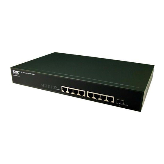
8-port web smart switch with poe
Hide thumbs
Also See for EZ Switch SMCGS8P-Smart:
- Management manual (366 pages) ,
- Installation manual (66 pages) ,
- Specifications (2 pages)

Related Manuals for SMC Networks EZ Switch SMCGS8P-Smart


Summary of Contents for SMC Networks EZ Switch SMCGS8P-Smart
-
Page 1: Management Guide
MANAGEMENT GUIDE SMCGS8P-Smart EZ Switch 10/100/1000 8-Port Web Smart Switch with PoE... - Page 3 EZ Switch 10/100/1000 Installation Guide From SMC’s EZ line of feature-rich workgroup LAN solutions 20 Mason Irvine, CA 92618 Phone: (949) 679-8000 July 2007 Pub. # 150000022900H E072007-DT-R02...
- Page 4 No license is granted by implication or otherwise under any patent or patent rights of SMC. SMC reserves the right to change specifications at any time without notice.
-
Page 5: Limited Warranty
“Active” SMC product. A product is considered to be “Active” while it is listed on the current SMC price list. As new technologies emerge, older technologies become obsolete and SMC will, at its discretion, replace an older product in its product line with one that incorporates these newer technologies. - Page 6 WHICH MAY VARY FROM STATE TO STATE. NOTHING IN THIS WARRANTY SHALL BE TAKEN TO AFFECT YOUR STATUTORY RIGHTS. * SMC will provide warranty service for one year following discontinuance from the active SMC price list. Under the limited lifetime warranty, internal and external power supplies, fans, and cables are covered by a standard one-year warranty from date of purchase.
-
Page 7: Table Of Contents
Contents Chapter 1: Introduction Description of Software Features Chapter 2: Initial Configuration Chapter 3: Configuring the Switch Using the Web Interface Navigating the Web Browser Interface Home Page Configuration Options Panel Display Main Menu Web Configuration Displaying Status Overview Showing Port Statistics Displaying the System Name Setting the Switch’s IP Address... - Page 8 Contents Appendix A: Software Specifications Software Features Management Features Standards Management Information Bases Appendix B: Troubleshooting Forgot or Lost Password Changing a PC’s IP Address...
- Page 9 Tables Table 3-1 Web Page Configuration Buttons Table 3-2 Switch Main Menu Table 3-3 Port Statistics Tables...
- Page 10 Tables...
- Page 11 Figures Figure 3-2 Front Panel Indicators Figure 3-3 Switch Information Figure 3-4 Port Statistics Figure 3-5 System Name Figure 3-6 LAN Settings Figure 3-7 Password Settings Figure 3-8 Reset to Factory Defaults Figure 3-9 Upgrade Firmware Figure 3-10 Upload/Download Configuration...
- Page 12 Figures viii...
-
Page 13: Chapter 1: Introduction
The switch supports flow control based on the IEEE 802.3x standard. Port Mirroring – The switch can unobtrusively mirror traffic from any port to a monitor port. You can then attach a protocol analyzer or RMON probe to this port to perform traffic analysis and verify connection integrity. - Page 14 This buffer can queue packets awaiting transmission on congested networks. Virtual LANs – The switch supports up to 64 VLANs. A Virtual LAN is a collection of network nodes that share the same collision domain regardless of their physical location or connection point in the network.
-
Page 15: Chapter 2: Initial Configuration
This should be done before you permanently install the switch in the network. Follow this procedure: Place your EZ Switch close to the PC that you intend to use for configuration. It helps if you can see the front panel of the switch while working on your PC. - Page 16 Initial Configuration...
-
Page 17: Chapter 3: Configuring The Switch
(Internet Explorer 5.5 or above, or Mozilla Firefox 1.0 or above). Prior to accessing the switch from a web browser, be sure you have first performed the following tasks: Configure the switch with a valid IP address, subnet mask, and default gateway. -
Page 18: Table 3-1 Web Page Configuration Buttons
Configuration Options Configurable parameters have a dialog box or a drop-down list. Once a configuration change has been made on a page, be sure to click on the Apply button to confirm the new setting. The following table summarizes the web page configuration buttons. -
Page 19: Table 3-2 Switch Main Menu
Panel Display The web agent displays an image of the switch’s ports. The port will turn green when the corresponding front-panel port is in connection with another device. To show the port number, place mouse pointer onto the intended port. - Page 20 LOGOUT Description Sets the rate limiting parameters for ports. Sets the broadcast storm control parameters. Sets up the port mirroring features of the switch to enable traffic monitoring. Diagnoses cable faults. Selects ports to group into static trunks. Configures trunk connection settings.
-
Page 21: Web Configuration
• Subnet Mask – This mask identifies the host address bits used for routing to specific subnets. (Default: 255.255.255.0) • Gateway IP Address – IP address of the gateway router between the switch and management stations that exist on other network segments. (Default: 0.0.0.0) •... - Page 22 • Trunk – The trunk label. “T1” through “T4” are used as trunk labels. • Type – All trunks and ports on this switch are 10/100/1000Mbps • Trunk Status – Indicates the speed and duplex setting of the trunk. This can be changed on the TRUNKS >...
-
Page 23: Figure 3-3 Switch Information
Web Configuration Web – Click STATUS, Overview. Figure 3-3 Switch Information... -
Page 24: Table 3-3 Port Statistics
You can display statistics on network traffic from the ports. These statistics can be used to identify potential problems with the switch (such as a faulty port or unusually heavy loading). All values displayed have been accumulated since the last system reboot, but can be reset to zero by clicking the CLEAR button. - Page 25 Table 3-3 Port Statistics (Continued) Parameter RMON Statistics Drop Events Received Frames Multicast Frames Undersize Frames Fragments Collisions Received Bytes Broadcast Frames CRC/Alignment Errors Oversize Frames Jabbers 64 Bytes Frames 65-127 Byte Frames 128-255 Byte Frames 256-511 Byte Frames 512-1023 Byte Frames 1024-1518 Byte Frames Description The total number of events in which packets were dropped due...
-
Page 26: Displaying The System Name
Figure 3-4 Port Statistics Displaying the System Name You can easily identify the system by displaying the device name. Field Attributes • Switch Name – A name assigned to the switch system. Web – Click System, Name. Figure 3-5 System Name 3-10... -
Page 27: Setting The Switch's Ip Address
Web – Click IP, General, Routing Interface System, LAN Settings. Enter the IP address, subnet mask and gateway, then click APPLY. Note that if you change the switch IP address, you must close the web interface and start a new session using the new IP address. -
Page 28: Configuring The Logon Password
APPLY. Tools On the Tools page, you can restore the switch to default settings, upgrade the firmware of the switch, or restart the switch. Restore to Factory Defaults Forces the switch to restore the original factory settings. -
Page 29: Figure 3-8 Reset To Factory Defaults
Figure 3-8 Reset to Factory Defaults Upgrade Firmware Upgrades the switch system firmware using a file provided by SMC. Select “Upgrade Firmware” from the Tools drop-down list then click on the “Browse” button to select the firmware file. Click the APPLY button to upgrade the selected switch firmware file. -
Page 30: Figure 3-10 Upload/Download Configuration
Figure 3-10 Upload/Download Configuration Restart Switch Web – Click SYSTEM, Tools, Restart Switch. To restart the switch, select from the Tools drop-down list, and then click APPLY. The reset will be complete when the user interface displays the login page. -
Page 31: Register Product
Register Product SMC request that you register your switch online, if you have not already done so. The Register Product page provides a convenient link to the SMC web site for this purpose. Web – Click System, Register Product. Click the Register Now button to access the SMC web site and register your switch. -
Page 32: Storm Control
• Rate(number of frames per second) – The Rate field is set by a single drop-down list. The same threshold is applied to every port on the switch. When the threshold is exceeded, packets are dropped, irrespective of the flow-control settings. -
Page 33: Port Mirroring
Note: If the total ingress bandwidth exceeds the mirror port’s egress bandwidth, packets will eventually be dropped on ingress to the switch, which means they will not reach the mirror port or their intended destination port. Input rate-limiting in conjunction with port flow-control should be used to ensure that the total ingress bandwidth never exceeds the egress bandwidth. -
Page 34: Cable Diagnostic
Web – Click PORTS, Port Mirroring. Cable Diagnostic You can perform cable diagnostics for all ports or selected ports to diagnose any cable faults (short, open etc..) and feedback a distance to the fault. Field Attributes • Cable Diagnostics – Cable diagnostics is performed on a per-port basis. Select the port number from the drop-down list. -
Page 35: Trunk Membership
This is the default state. • Trunk T1-T4 – These columns correspond to the four trunks that are supported by the switch. To assign a port to a trunk, click on the radio button in the corresponding column, then click APPLY. -
Page 36: Trunk Configuration
Web – Click TRUNKS, Membership. To assign a port to a trunk, click the required trunk number, then click APPLY. Trunk Configuration Field Attributes • Trunk – Indicates trunk identification. • Speed/Duplex – Allows you to manually set the port speed and duplex mode for all ports in the trunk. -
Page 37: Trunk Rate Limit
LACP-configured ports on another device. You can configure any number of ports on the switch as LACP, as long as they are not already configured as part of a static trunk. If ports on another device are also configured as LACP, the switch and the other device will negotiate a trunk link between them. -
Page 38: Lacp Status
Web – Click TRUNKS, Settings. LACP Status This page displays the LACP status of the switch. LACP Aggregation Shows the status of each port. The LACP Aggregation table has one row for each LACP group. Normal means no LACP group is active. For active LACP groups, a new row is created from which the status of its port members are displayed. -
Page 39: Vlan Settings
LACP Port Status Shows LACP port status. Field Attributes • Port - The port number. • Port Active - Shows if the port is a member of an active LACP group. • Partner Port Number - A list of port numbers assigned to the link by the LACP partner. - Page 40 • All ports are members of VLAN 1 • The switch management interface is on VLAN 1 (this cannot be changed) • All ports have a Port VLAN ID (PVID) of 1 • All ports can send and receive both VLAN-tagged and untagged packets (that is,...
-
Page 41: 802.1X
With IEEE 802.1X (802.1X), access to all switch ports in a network can be centrally controlled from a server, which means that authorized users can use the same credentials for authentication from any point within the network. - Page 42 • Reauthentication Period - Sets the time period after which a connected client must be re-authenticated. • EAP timeout - The time the switch shall wait for the supplicant response before re-transmitting a packet. Port Setting •...
-
Page 43: Figure 3-23 802.1X Configuration
Web Configuration Web – Click 802.1X, Settings. Figure 3-23 802.1X Configuration 802.1X Field Attributes • Port Statistics - Statistics can be viewed on a per-port basis. Select the port that you want to view here. • Authenticator counters - General statistics for authenticator. •... -
Page 44: Lldp
Configuring the Switch Web – Click 802.1X, Statistics. Figure 3-24 802.1X Statistics LLDP This page allows you to configure the Link Layer Discovery Protocol (LLDP) configuration. LLDP allows devices on the network to share information about themselves for the reasons of simplified troubleshooting, enhanced network management, and maintaining an accurate network topology. -
Page 45: Lldp Neighbor Table
Web – Click LLDP, Settings. LLDP Neighbor Table This page displays the LLDP Neighbor Table. This table provides information on neighboring devices. The table contains the following seven columns: Field Attributes • Local Port - The local port of the neighboring device. •... -
Page 46: Snmp
Access rights to the onboard agent are controlled by community strings. To communicate with the switch, the management station must first submit a valid community string for authentication. Field Attributes •... -
Page 47: Poe
When a device is connected to a switch port, its power requirements are detected by the switch before power is supplied. - Page 48 Configuring the Switch Web – Click PoE, Settings. Figure 3-28 POE Configuration 3-32...
-
Page 49: Appendix A: Software Specifications
Appendix A: Software Specifications Software Features Authentication RADIUS, Port (802.1X), Port Security DHCP Client Port Configuration 100BASE-TX: 10/100 Mbps, half/full duplex 1000BASE-T: 10/100 Mbps at half/full duplex, 1000 Mbps at full duplex Flow Control Full Duplex: IEEE 802.3-2005 Half Duplex: Back pressure Broadcast Storm Control Traffic throttled above a critical threshold Port Mirroring... -
Page 50: Management Features
Management Features In-Band Management Web-based HTTP, SNMP manager Software Loading HTTP in-band SNMP Management access via MIB database Trap management Standards IEEE 802.1D Spanning Tree Protocol IEEE 802.1p Priority tags IEEE 802.1Q VLAN IEEE 802.1X Port Authentication IEEE 802.3-2005 Ethernet, Fast Ethernet, Gigabit Ethernet Full-duplex flow control Link Aggregation Control Protocol IEEE 802.3ac VLAN tagging... -
Page 51: Appendix B: Troubleshooting
Appendix B: Troubleshooting Forgot or Lost Password If you have forgotten the administration password you can return the switch to its factory default state by following these steps: Remove the power cord from the back of the switch. Remove all cables from the front-panel ports. - Page 52 In the Internet Protocol (TCP/IP) Properties dialog box, click to select Use the following IP address. Then type your intended IP address, Subnet mask, and Default gateway in the provided text boxes. Click OK to save the changes. Note: For users of systems other than Windows 2000 or Windows XP, refer to your system documentation for information on changing the PC’s IP address.
- Page 54 Technische ondersteuningsinformatie beschikbaar op www.smc.com PORTUGUES Informações sobre Suporte Técnico em www.smc.com SWEDISH Information om Teknisk Support finns tillgängligt på www.smc.com INTERNET E-mail address: techsupport@smc.com Driver updates http://www.smc.com/ index.cfm?action=tech_support_drivers_downloads World Wide Web http://www.smc.com/ 20 Mason • Irvine, CA 92618 • Phn: 949-679-8000 • www.smc.com...