Raymarine SmartPilot S1000 Installation Manual
Raymarine s1000 autopilot system: installation guide
Hide thumbs
Also See for SmartPilot S1000:
- Manual (80 pages) ,
- User manual (40 pages) ,
- Installation manual (39 pages)

Related Manuals for Raymarine SmartPilot S1000


Summary of Contents for Raymarine SmartPilot S1000
-
Page 1: Installation Guide
SmartPilot S1000 Autopilot Installation Guide Document Number: 87040-3 Date: February 2005... -
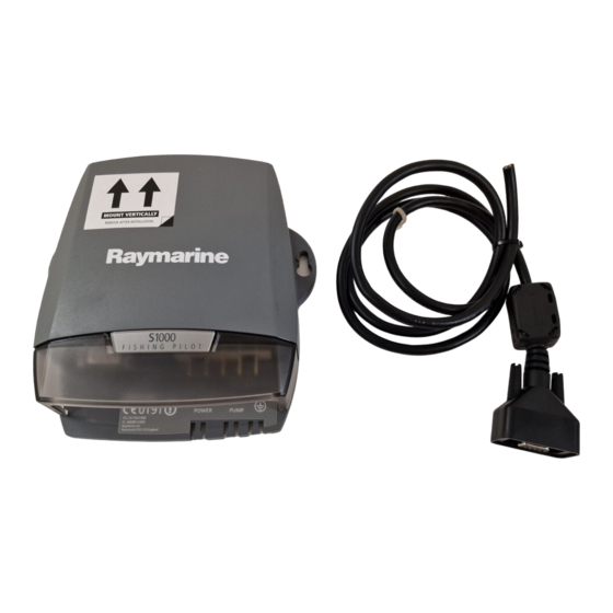
Page 2: Autopilot System Overview
Welcome to the Raymarine S1000 Autopilot Congratulations on having bought a Raymarine S1000 Autopilot. This state-of-the-art product is specifically designed to be easily integrated with your boat’s steering system, and enable you to automatically control the steering. S1000 Autopilot System... -
Page 3: Installation Overview
S1000 Autopilot Installation Guide Installation overview Connect the autopilot pump to your existing steering system. Page 9 Bleed the steering system. Page 12 Secure the autopilot pump. Page 16 Fit the course computer. Page 17 Fit miscellaneous items Page 18... -
Page 4: This Guide
This guide Before starting to install your S1000 Autopilot, please take time to read this guide. In particu- lar, please take note of the safety and electromagnetic compatibility (EMC) information at the end of this guide. WARNING: This product must be installed and operated in accordance with the Raymarine instructions provided. -
Page 5: What You Need
S1000 Autopilot Installation Guide What you need Parts supplied Elbow fitting, x 4 Autopilot Pump Straight fitting x 2 Anti-vibration mounts x 2 'T' fitting x 2 High pressure Low pressure steering hoses transparent (x 2) bleeding hose Nitrile gloves Wrench 12 mm AF x 19 mm AF Drill 3.4 mm... - Page 6 Tools & materials required Drill S1000 Autopilot Installation Guide Pencil Screwdriver, No. 2 Pozidriv Countersink Screwdriver, Screwdriver, small, medium, flat blade flat blade Absorbent, disposable wipes...
-
Page 7: Locating The Course Computer
If you have internet access, please view the installation video on line at www.raymarine.com. Before you disturb your hydraulic steering system, we strongly recommend that you consult the manufacturer and read the steering system manuals. - Page 8 No sharp bends, kinks or chafing of tube. Mount pump location either horizontally or with connector end up. Do not mount pump with connector end down. S1000 Autopilot Installation Guide Install in a dry location.
- Page 9 S1000 Autopilot Installation Guide Using the hydraulic hoses Three, pre-assembled hydraulic hoses are supplied. Two of these are dark-colored, high pressure steering hoses and the third is a transparent low-pressure hose. The transparent hose is intended to help you check for air bubbles when bleeding the system and must be used only to connect the autopilot pump reservoir to the lower connector on the helm pump.
- Page 10 Hand tighten CAUTION: Do not exceed 13 ft/lbs (17.6 Nm) torque. DO NOT EXCEED 2.5 TURNS in total, from hand tight. S1000 Autopilot Installation Guide Do not apply sealant to hose connection thread. CAUTION: Do not exceed 13 ft/lbs (17.6 Nm) torque.
-
Page 11: Connecting The Autopilot Pump
S1000 Autopilot Installation Guide Installation procedures 1. Connecting the autopilot pump Connecting the autopilot pump, sheet 1 WARNING: Do not allow hydraulic fluid to come into contact with your skin. Wear the protective nitrile gloves provided when working with hydraulic fluid. - Page 12 S1000 Autopilot Installation Guide Remove & retain the helm pump Remove & retain the helm pump breather cap.
- Page 13 S1000 Autopilot Installation Guide Connecting the autopilot pump, sheet 3 Connect hydraulic steering hoses from autopilot pump Port and Starboard connectors to the Port and Starboard connectors on the helm pump, so that Port connects to Port, and Starboard connects to Starboard .
-
Page 14: Bleeding The Steering System
‘spongy’ and ‘lumpy’ to operate. To return the steering system to smooth operation, use the procedure given here to bleed the air from the system. Bleed procedure, sheet 1 Top up the helm pump with hydraulic fluid. Loosen the autopilot pump bleed screw 2 full turns. S1000 Autopilot Installation Guide... - Page 15 S1000 Autopilot Installation Guide Bleed procedure, sheet 2 Using a suitable screwdriver, turn the autopilot pump shaft so that the flat on the shaft is toward the PORT side of the pump. SLOWLY turn the wheel counter-clockwise and observe the bubbles in the transparent tube. Keep the helm pump reservoir topped up while doing this.
- Page 16 Keep the helm pump reservoir topped up while doing this. Keep turning the wheel counter-clockwise until there are no more bubbles i.e. so the hydraulic fluid in the transparent tube is clear. S1000 Autopilot Installation Guide...
- Page 17 S1000 Autopilot Installation Guide Bleed procedure, sheet 4 Top up the hydraulic fluid. Turn the autopilot pump bleed screw, fully clockwise, and hand-tighten it. Replace the helm pump breather cap. Correct fluid level Helm pump This completes the bleed procedure.
- Page 18 Countersink the pilot holes to prevent damage to the mounting surface. S1000 Autopilot Installation Guide Drill two 1/8" (3.4 mm) pilot holes for the fixing screws. Slide the anti-vibration mounts onto the pump bracket feet, then secure the pump with the screws provided.
- Page 19 S1000 Autopilot Installation Guide 4. Fitting the course computer Securing course computer Mark holes for fixing screws. Countersink the pilot holes to prevent damage to the mounting surface. Drill two 1/8" (3.4 mm) pilot holes for fixing screws. Partially screw in the screws provided, then slot the course computer onto the screws, and tighten screws.
-
Page 20: Safety Alarm
Mark holes for fixing screws. Countersink the pilot holes to prevent damage to the mounting surface. Fitting batteries in S100 Remote S1000 Autopilot Installation Guide Drill two 1/8" (3.4 mm) pilot holes. Secure the safety alarm with the screws provided. - Page 21 S1000 Autopilot Installation Guide Fitting S100 Remote cradle At fixed position Mark holes for the fixing screws. Drill three 1/8" (3.4 mm) pilot holes for the fixing screws. Countersink the pilot holes to prevent damage to the mounting surface. Secure the cradle.
- Page 22 Fit the in-line power switch in a readily-accessible location. Securing When all items have been fitted, connect up the system electrics. S1000 Autopilot Installation Guide Cut 11/16" (18 mm) inch (5 mm) maximum Ensure the protrusion on the switch barrel goes fully into...
-
Page 23: Electrical Connections Overview
S1000 Autopilot Installation Guide 6. Electrical connections Overview Summary WARNING: Before making electrical connections to any part of the S1000 system, ensure the power source for the system is switched off. Course Computer Data cable RF ground See Diagram A... -
Page 24: Connecting Wires
(world wide). Failure to provide an RF ground when the S1000 Autopilot is installed could result in a degraded electromagnetic performance and may affect the operation of the system. - Page 25 S1000 Autopilot Installation Guide Diagram A: Connecting RF ground - preferred method S1000 Autopilot Product Code: A18107 FCC ID PJ5S1000 IC: 4069B-S1000 Raymarine Ltd Portsmouth PO3 5TD England If the boat does not have a ground plate, use the alternative method shown in the following diagram, to connect the RF ground.
-
Page 26: Connecting Power And Autopilot Pump
0191 FCC ID PJ5S1000 IC: 4069B-S1000 Raymarine Ltd Portsmouth PO3 5TD England Black 12 V Power supply power switch S1000 Autopilot Installation Guide Course computer POWER PUMP Brown Integral 10 A fuse In-line Now make the necessary Data Cable connections. -
Page 27: Connecting The Data Cable
For details of the NMEA Spur cable connections, refer to Diagram D Each time power is applied to an S1000 Autopilot connected to a Raymarine GPS (via NMEA or SeaTalk), the S1000 will set the GPS filtering to WEAK. If you want to connect to an external SeaTalk system, ensure each of these SeaTalk wires connects to the wire of the same color in the external system. -
Page 28: Using With Raymarine Gps
(see Diagram C) S1000 Autopilot Installation Guide Using with Raymarine GPS If a Raymarine GPS (such as the Raystar 120 or 125) is to be connected to the S1000 Autopilot via NMEA, NMEA in out, +ve correctly connected. - Page 29 S1000 Autopilot Installation Guide Secure wires Course Computer POWER PUMP Post installation This completes the installation procedure. Now carry out the procedures (below).
-
Page 30: Post Installation
If the steering feels uneven and/or less responsive than it was before you installed your S1000 Autopilot, you may need to bleed the entire steering system. To do this, use the purge procedure at the following web address: http://www.seastarsteering.com/OUTBOARD/oboard.htm?../FILL_PURGE/FillPurge.htm&1... - Page 31 Autolearn procedure 3. Carry out the Checking direction of turn - sheet 1 Before casting off, check that the S1000 operates the boat's steering system in the correct direction: At the S100 Remote, hold down STANDBY for 2 seconds, to enter Setup mode.
- Page 32 If the outboard motor(s) does/do not move correctly, DO NOT USE THE BOAT. At the S100 Remote, hold down STANDBY for 2 seconds to leave Setup mode and return to Standby mode, then check that the S1000 components have been installed correctly. In particular, check that the autopilot pump wiring and hydraulics are connected correctly.
- Page 33 Autolearn procedure - sheet 2 To regain control of the boat at any time during Autolearn, Before you use the S1000 Autopilot, run the inbuilt Autolearn facility to set up the autopilot for your boat: If the system is not already in Setup mode, at the S100 Remote, hold down STANDBY for 2 seconds, to enter Setup mode.
-
Page 34: Specifications
Hose connection thread: Hydraulic fluid Recommended Type: SeaStar/BayStar Marine Steering Fluid Other suitable Types: Texaco HO15 Shell Aero 4 Esso Univis N15 Chevron Aviation Fluid A Mobil Aero HFA Fluids meeting MIL H5606 specifications S1000 Autopilot Installation Guide UNEF (Unified Extra Fine) -
Page 35: General Information
Information To the best of our knowledge, the information in this guide was correct when it went to press. However, Raymarine cannot accept liability for any inaccuracies or omissions it may contain. In addition, our policy of continuous product improvement may change specifications without notice. Therefore, Raymarine cannot accept liability for any differences between the product and this guide. -
Page 36: Suppression Ferrites
Raymarine. Connections to Other Equipment If your Raymarine equipment is to be connected to other equipment using a cable not supplied by Raymarine, a suppression ferrite MUST always be attached to the cable near the Raymarine unit.