Advertisement
Quick Links
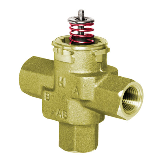
The VC hydronic valve consists of a valve body and replaceable
characterized cartridge assembly.
Depending on the valve model selected, they can be used with a
VC2114 or VC8114 series actuator to provide on-off flow control, or
with a VC6930 or VC7930 series actuator to provide proportional flow
control. Two way bodies may be plumbed in either direction. Three-way
bodies may be used in either diverting or mixing applications.
Replacing the cartridge rebuilds the valve. The valve body should be
able to stay in the pipes indefinitely.
VC actuators, ordered separately, use cam-operated cartridge travel to
resist water hammer. Limit switches prevent motor overrun.
The specifications following are nominal and conform to generally
accepted industry standards. Honeywell is not responsible for
damages resulting from misapplication or misuse of its products or
non-workmanlike installation practices.
Operating Ambient:
32 to 150°F [0 to +65°C].
5-95% RH (non-condensing)
Fluid temperatures:
34 to 203°F [1 to 95°C]
Shipping and Storage Temperature:
-40 to 150°F [-40 to +65°C]
Atmosphere:
Non-corrosive, non-explosive.
Valve Materials:
Body of bronze Cartridge of Ryton (polyphenylene sulphide)
and Noryl (polyphenylene oxide)
O-ring seals of EPDM rubber
Stem of stainless steel
Pressure Rating:
Static - 300 psig [20 Bar] maximum.
Burst - 1500 psig [100 Bar]
Operating Differential and Close-off - 60 psi maximum [4 bar]
Stem Travel:
0.4 inches [10 mm]
Flow Characteristics:
Linear or equal percentage, per Table 2.
Spring Force:
1000 and 6000 Series(Silver): 14 lbf.
3000 and 7000 Series(Red): 20 lbf.
2007.05 Printed in Canada
Cartridge Valve for Use with VC Series
SPECIFICATIONS
VCZA,B,M,N Series
68 [2-3/4]
94 [3-3/4]
D
A
C
Figure 1 - Nominal dimensions in inches [millimetres]
[1]
Dimensio n
mm Inches mm Inches mm Inches
Pipe Fitting Sizes
1/2" SWEAT
89
98
1/2" NPT (int.)
3/4" NPT (int.)
3/4" SWEAT
94
1" NPT (int.)
1" SWEAT
1-1/4" SWEAT
110 4-5/16
1-1/4" NPT (int.)
[1] All models not available in all countries
Table 1: VC Valve assembled dimensions
94 [3-3/4]
90 [3-9/16]
A
B
B
AB
C
C
D
E
3-1/2
130
5-1/8
111 4-3/8
3-7/8
136 5-11/32
130
5-1/8
132 5-3/16
3-11/16
113 4-7/16
136
5-11/32
118
4-5/8
142
5-5/8
Form No. 95C-10948
E
Advertisement

Related Manuals for Honeywell VCZB Series


Summary of Contents for Honeywell VCZB Series
- Page 1 94 [3-3/4] 68 [2-3/4] 94 [3-3/4] The specifications following are nominal and conform to generally accepted industry standards. Honeywell is not responsible for damages resulting from misapplication or misuse of its products or non-workmanlike installation practices. 90 [3-9/16] Operating Ambient: 32 to 150°F [0 to +65°C].
- Page 2 Accessories and Replacement Parts: 40007029-002: Cartridge installation wrench (included with all VCZZ replacement cartridges) 272866B: Valve caps for system flushing (10 per pack) 2-way Replacement Cartridges: 3-way Replacement Cartridges: VCZZ1000: quick open VCZZ6000: quick open VCZZ1100: high Cv, linear flow VCZZ6100: high Cv, linear flow VCZZ3100: high Cv, linear flow VCZZ7100: high Cv, linear flow...
- Page 3 300 psig (20 bar). They are to be TIGHTEN. Maximum torque limit is 33 ft-lb for the 22 mm operated with the appropriate Honeywell actuators only. compression fitting, and 48 ft-lb for the 28 compression fitting. Water must be properly filtered, treated and conditioned according to local conditions.
- Page 4 Actuator" below. 8. Reconnect leadwires or Molex™ connector if necessary. NOTE: Honeywell VC series hydronic valves are designed and 9. Refill hydronic system or restore system flow by opening isolating tested for silent operation in properly designed and installed valves.