Table of Contents
Advertisement
Available languages
Available languages
Quick Links
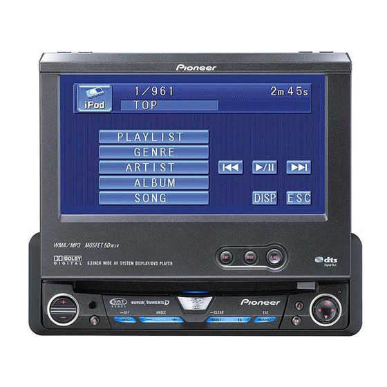
AVH-P4900DVD
This product conforms to CEMA cord colors.
Le code de couleur des câbles utilisé pour ce produit est
conforme à CEMA.
Printed in Japan
Imprimé au Japon
<CRD4195-A> UC
<KSNNF> <07B00000>
Connecting the Units
WARNING
CAUTION:
• To avoid the risk of accident and the
• PIONEER does not recommend that you
potential violation of applicable laws,
install or service your display yourself.
the front DVD or TV (sold separate-
Installing or servicing the product may
ly) feature should never be used
expose you to risk of electric shock or
while the vehicle is being driven.
other hazards. Refer all installation and
Also, Rear Displays should not be in
servicing of your display to authorized
a location where it is a visible distrac-
Pioneer service personnel.
tion to the driver.
• Secure all wiring with cable clamps or
• In some countries or states the view-
electrical tape. Do not allow any bare
ing of images on a display inside a
wiring to remain exposed.
vehicle even by persons other than
the driver may be illegal. Where such
• Do not drill a hole into the engine com-
regulations apply, they must be
partment to connect the yellow lead of
obeyed and this unit's DVD features
the unit to the vehicle battery. Engine
should not be used.
vibration may eventually cause the insu-
lation to fail at the point where the wire
passes from the passenger compartment
into the engine compartment. Take extra
care in securing the wire at this point.
• It is extremely dangerous to allow the
display lead to become wound around
the steering column or gearshift. Be sure
to install the display in such a way that it
will not obstruct driving.
• Make sure that wires will not interfere
with moving parts of the vehicle, such as
the gearshift, parking brake or seat slid-
ing mechanism.
• Do not shorten any leads. If you do, the
protection circuit may fail to work prop-
erly.
ENGLISH
Note:
•
Control signal is output through blue/white cable
•
This unit cannot be installed in a vehicle that
when this unit is powered on. Connect it to an
does not have an ACC (accessory) position on
external power amp's system remote control or
the ignition switch. (Fig. 1)
the vehicle's auto-antenna relay control terminal
(max. 300 mA, 12 V DC). If the vehicle is
equipped with a glass antenna, connect it to the
antenna booster power supply terminal.
•
Never connect blue/white cable to external power
amp's power terminal. Also, never connect it to
the power terminal of the auto antenna.
Otherwise, battery drain or malfunction may
result.
•
IP-BUS connectors are color-coded. Be sure to
ACC position
No ACC position
connect connectors of the same color.
Fig. 1
•
Black cable is ground. This cable and other prod-
uct's ground cable (especially, high-current prod-
ucts such as power amp) must be wired separate-
•
Use this unit in other than the following condi-
ly. Otherwise, fire or malfunction may result if
tions could result in fire or malfunction.
they are accidentally detached.
— Vehicles with a 12-volt battery and negative
grounding.
•
Cord function may differ according to the
— Speakers with 50 W (output value) and 4 ohm
product, even if cord color is the same. When
to 8 ohm (impedance value).
connecting this system, be sure to check all
•
To prevent short-circuit, overheating or malfunc-
manuals and connect cords correctly.
tion, be sure to follow the directions below.
— Disconnect the negative terminal of the battery
before installation.
— Secure the wiring with cable clamps or adhe-
sive tape. To protect the wiring, wrap adhesive
tape around them where they lie against metal
parts.
— Place all cables away from moving parts, such
as gear shift and seat rails.
— Place all cables away from hot places, such as
near the heater outlet.
— Do not pass the yellow cable through a hole
into the engine compartment to connect to a
battery.
— Cover any disconnected cable connectors with
insulating tape.
— Do not remove RCA caps if RCA cables are
not used.
— Do not shorten any cables.
— Never cut the insulation of the power cable of
this unit in order to share the power to other
equipment. Current capacity of the cable is
limited.
— Use a fuse of the rating prescribed.
— Never wire the speaker negative cable directly
to ground.
— Never band together multiple speaker's nega-
tive cables.
Advertisement
Table of Contents

Related Manuals for Pioneer AVH-P4900DVD


Summary of Contents for Pioneer AVH-P4900DVD
- Page 1 Connecting the Units CAUTION: • PIONEER does not recommend that you install or service your display yourself. Installing or servicing the product may expose you to risk of electric shock or other hazards. Refer all installation and servicing of your display to authorized Pioneer service personnel.
-
Page 2: Connecting Power Cord
Connecting the Units Connecting the Units Connecting the power cord 15 cm (5-7/8 in.) IP-BUS input (Blue) 15 cm (5-7/8 in.) This product Multi-CD player (sold separately) IP-BUS cable Yellow/black If you use an equipment with Mute function, wire this lead to the Audio Mute lead on that equipment. -
Page 3: Connecting With Rear Camera
Do not use this function for entertainment purposes. • The object in rear view may appear closer or more distant than in reality. CAUTION Pioneer recommends the use of a camera which outputs mirror reversed images, 20 cm otherwise screen image (7-7/8 in.) -
Page 4: Installation
Connecting the Units ENGLISH Installation When connecting the external video component and the display Note: • Check all connections and systems before final installation. Audio input • Do not use unauthorized parts. The use of unautho- rized parts may cause malfunctions. •... -
Page 5: Raccordements Des Appareils
• Pour éviter tout risque d’accident, et véhicule dont le contacteur d’allumage n’a pas de position ACC (accessoire). (Fig. 1) • PIONEER ne vous recommande pas toute infraction aux lois en vigueur, d’installer ou d’entretenir vous-même l’affichage à l’avant d’image de DVD cet écran, car ces travaux peuvent... -
Page 6: Branchement Du Cordon D'alimentation
Raccordements des appareils Branchement du cordon d’alimentation 15 cm Câble d’antenne (fourni) Entrée IP-BUS (Bleu) 15 cm Cet appareil Lecteur de CD à chargeur (vendu séparément) Câble IP-BUS Jaune/noir Si vous utilisez un appareil muni d’une fonction de mise en sourdine, connectez ce conducteur au conducteur de sourdine audio de cet appareil. -
Page 7: Raccordements À Une Caméra De Recul
Elle ne doit pas être utilisée à des fins de divertissement. • L’objet vu dans le rétroviseur peut apparaître plus proche ou plus loin qu’en réalité. ATTENTION Pioneer conseille l’utilisation d’une caméra qui fournit des images inversées, comme 20 cm dans un miroir;... - Page 8 Raccordements des appareils FRANÇAIS Installation Raccordements à un appareil vidéo externe et à un écran Remarque: • Vérifiez toutes les connexions et tous les systèmes avant l’installation finale. Entrée audio • N’utilisez aucune pièce non autorisée. L’utilisation de pièces non autorisées peut causer un mauvais fonctionnement.