Advertisement
Quick Links
TUP: GD1000F*0/PGD1000W* 0 / PGD1010YW0
Terminale versione montaggio
Terminale versione da incasso
a parete (connettore telefonico)
Panel mounting terminal
PGD1***F*0
Wall mounting terminal (telephone jack)
PGD1***W*0
Fig. 1
Terminale versione montaggio a parete (connettore a morsetti)
Wall-mounting version terminal (clamp connector)
PGD1***Y*0
pair 1
pair 2
F
E
A
B
shielded twisted pair Rs485 cable from TCONN6000 (pCO)
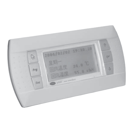
pCO display grafico / pCO Graphic Display
Vi ringraziamo per la scelta fatta, sicuri che sarete soddisfatti del vostro acquisto.
Il display grafico pGD è un dispositivo elettronico, compatibile con i precedenti terminali della linea PCOI/PCOT, che
consente la completa gestione della grafica tramite la visualizzazione di icone (definite a livello di sviluppo software applicativo) e
la gestione di font internazionali di due dimensioni: 5x7 e 11x15 pixel. Il software applicativo è residente soltanto sulla scheda pCO,
il terminale non ha bisogno di nessun software aggiuntivo in fase di utilizzo.
Inoltre il terminale offre un ampio range di temperatura di funzionamento (-20T60 °C) e nella versione ad incasso il frontale garan-
tisce un elevato grado di protezione (IP65).
Codici dei modelli
Green Backlight
Versione da incasso
PGD1000F00
o pannello
Versione da parete
PGD1000W00
Versione da parete con
connettore con morsetti
a vite
Montaggio a pannello (cod. PGD1000F*0)
Questi terminali sono stati progettati per il montaggio a pannello; la dima di foratura deve avere dimensioni di 127x69 mm + 2
fori circolari diametro 4 come indicato in Fig. 9. Per l'installazione seguire le istruzioni riportate di seguito:
• Effettuare il collegamento del cavo telefonico;
• Inserire il terminale, privo di cornice frontale, nel foro, e mediante le viti a testa svasata, contenute all'interno dell'imballo,
fissare il dispositivo al pannello nelle sedi indicate in Fig. 1;
• Infine, installare la cornice a scatto.
Montaggio a parete (cod. PGD1000W*0)
A
Il montaggio a parete del terminale prevede l'iniziale fissaggio del retrocontenitore A (Fig. 2), per mezzo di una scatola standard
a 3 moduli per interruttori.
• Fissare il retrocontenitore alla scatola tramite le viti a testa bombata presenti all'interno dell'imballo;
• collegare il cavo telefonico (cod. S90CONN00*) proveniente dalla scheda pCO all'apposito connettore (RJ12) posto sul retro
del terminale;
• appoggiare il frontale al retrocontenitore e fissare il tutto utilizzando le viti a testa svasata presenti all'interno dell'imballo
come illustrato in Fig. 2;
• infine, installare la cornice a scatto.
Montaggio a parete (cod. PGD1010YW0)
Il montaggio del terminale PGD1010YW0 è possibile anche con cablaggio a "vista" utilizzando il retroncontenitore F, che deve
essere inizialmente fissato alla parete (fig.3).
Fig. 2
1.
Fissare al muro "l'adattatore per il montaggio a parete" per mezzo di viti (A)
2.
Rimuovere la camicia e la blindatura del cavo per circa 12 cm (la blindatura non deve essere collegata)
3.
Fissare il cavo al pezzo posteriore mediante il morsetto (B)
4.
Passare il conduttore a coppia intrecciata attraverso il foro (D) del pezzo posteriore (usare il cavo ritorto a 2 coppie AWG24)
5.
Fissare il pezzo posteriore all'adattatore per mezzo di viti (C)
6.
Collegare le coppie di conduttori al terminale delle viti del display PGD. Fate attenzione: collegamenti errati possono danneggia-
re PGD, pCO e gli altri dispositivi sulla rete pLAN
Tenere i
conduttori
piegati in
questa zona!
7.
Infine, fissare il pGD al pezzo posteriore piegando il conduttore solo sul lato destro della scatola (vista frontale)
Istruzioni di montaggio (PGD1***Y*0)
È possibile configurare l'indirizzo del terminale solo dopo aver fornito alimentazione allo stesso tramite il connettore
telefonico RJ12 (il valore preimpostato in fabbrica è 32).
Per entrare in modalità configurazione premere contemporaneamente i tasti (sempre presenti in tutte le versioni) per alme-
no 5 secondi; verrà visualizzata la maschera di Fig. 4 con il cursore lampeggiante nell'angolo in alto a sinistra:
• Per modificare l'indirizzo del terminale (display address setting) premere una volta il tasto : il cursore si sposterà sul campo
indirizzo (nn).
D
• Tramite i tasti selezionare il valore voluto, e confermare ripremendo il tasto . Se il valore selezionato è diverso da quello memo-
rizzato precedentemente apparirà la maschera di Fig. 5 e il nuovo valore verrà memorizzato nella memoria permanente del display.
Se si imposta il campo nn al valore 0, il terminale comunicherà con la scheda pCO usando il protocollo "punto-punto" (non
C
pLAN) e il campo "I/O Board address: xx" scompare in quanto privo di significato.
pCO: assegnazione lista terminali privati e condivisi
A questo punto, se fosse necessario modificare la lista dei terminali associata ad ogni singola scheda pCO, si dovrà seguire la
seguente procedura:
• entrare nella modalità configurazione con i tasti , come descritto nel paragrafo precedente;
• premere il tasto fino a che il cursore si posiziona sul campo xx (I/O board address) Fig. 4;
• tramite i tasti scegliere l'indirizzo della scheda pCO desiderata. I valori selezionabili saranno solo quelli delle schede pCO
effettivamente in linea. Se la rete pLAN non funziona correttamente, oppure non è presente nessuna scheda pCO, non sarà
possibile modificare il campo che mostrerà solo "—";
• premendo ancora una volta il tasto verranno visualizzate in sequenza le maschere di Fig. 6;
• anche qui il tasto muove il cursore da un campo all'altro e i tasti cambiano il valore del campo corrente. Il campo P:xx
mostra l'indirizzo della scheda selezionata; nell'esempio di figura è stata selezionata la 12;
Fig. 3
• per uscire dalla procedura di configurazione e memorizzare i dati selezionare il campo "OK ?" impostare Yes e confermare con
il tasto .
White Backlight
Green Backlight con buzzer White Backlight con buzzer
PGD1000FW0
PGD1000FZ0
PGD1000FX0
PGD1000WW0
PDG1000WZ0
PGD1000WX0
PGD1010YW0
Tab.1
Pair 1: VL-GND
Pair 2: Tx+/Rx+, Tx-/Rx-
Thank you for your choice. We trust you will be satisfied with your purchase.
The pGD graphic display is an electronic device that is compatible with the previous PCOI/PCOT line terminals; it allows complete
management of graphics by the display of icons (defined at an application software development level), as well as the manage-
ment of international fonts, in two sizes: 5x7 and 11x15 pixels.The application software resides on the pCO board, and therefore
the terminal does not require any additional software for operation.
Furthermore, the terminals feature a wide operating temperature range (-20T60 °C) and in the built-in version, the front panel
ensures a high index of protection (IP65).
Model codes
Green Backlight
White Backlight
Green Backlight with buzzer
Built-in or panel-mounted
PGD1000F00
PGD1000FW0
PGD1000FZ0
version
Wall-mounted version
PGD1000W00
PGD1000WW0
PDG1000WZ0
Wall-mounting version
with screw clamps
PGD1010YW0
connector
Panel-mounted version (code PGD1000F*0)
These terminals have been designed for panel installation; the drilling template measures 127x69 mm and has 2 circular holes, 4
mm in diameter, as shown in Fig. 9. For installation, proceed as follows:
• Connect the telephone cable;
• Insert the terminal, with the front frame removed, into the opening, and fasten the device to the panel using the flush-head
screws, supplied in the packaging, as shown in Fig. 1;
• Finally, fit the click-on frame.
Wall-mounted version (code PGD1000W*0)
The wall-mounting of the terminal first requires the back piece of the container A (Fig. 2) to be fitted, using a standard three-
module switch box.
• Fasten the back piece to the box using the rounded-head screws supplied in the packaging;
• Connect the telephone cable (code S90CONN00*) from the pCO board to the connector provided (RJ12) on the rear of the
terminal;
• Rest the front panel on the back piece and fasten the parts together using the flush-head screws supplied in the packaging,
as shown in Fig. 2;
• Finally, fit the click-on frame.
Assembly instructions (cod. PGD1010YW0)
It is also possible to mount terminal PGD1010YW0 with "visible" cabling using back piece F, which must be secured to the wall
(fig.3) beforehand.
1.
Fix the "wall mounting adapter" to the wall by screws (A)
2.
Remove cable jacket and shield for about 12 cm (shield must be not connected)
3.
Fix the cable to the back piece by the clamp (B)
4.
Pass the the twisted pair conductor through the hole (D) of back piece (use AWG24 2 pair twisted cable)
5.
Fix the back piece to the adapter by screws (C)
6.
Connect the conductor pairs to the screw terminal of PGD display: be careful, wrong connections may damage PGD, pCO and
other devices on pLAN network
Keep the
folded
conductors
in this area!
7.
Finally, fix the pGD to the back piece folding the conductor only on the right side of the enclosure (front view)
Electrical connection (PGD1***Y*0)
The address of the terminal can be configured only after having connected the power supply, using the RJ12 telephone jack
(the factory default value is 32).
To access configuration mode, press the buttons (present on all versions) together and hold them for at least 5 seconds;
the screen shown in Fig. 4 will be displayed, with the cursor flashing in the top left corner:
• To change the address of the terminal (display address setting), press the button once: the cursor will move to the address
field (nn).
• Use the buttons to select the desired value, and confirm by pressing again. If the value selected is not the same as the
one saved previously, the screen shown in Fig. 5 will be displayed, and the new value will be saved to the permanent memory.
If the field nn is set to 0, the terminal will communicate with the pCO board using "point-to-point" protocol (not pLAN) and the
field "I/O Board address: xx" will not be displayed, as it has no meaning.
pCO: assigning the list of private and shared terminals
At this point, if the list of terminals associated with each individual pCO board needs to be modified, proceed as follows:
• access configuration mode using the buttons, as described in the previous paragraph;
• press the button until the cursor moves to the field xx (I/O board address) Fig. 4;
• use the buttons to select the pCO board in question. The values available correspond to the pCO boards that are effecti-
vely on line. If the pLAN network is not working correctly, or if no pCO board is present, the field cannot be modified, and the
symbol "—" will be displayed;
• pressing again displays the screens shown in Fig. 6, in sequence;
• here too, the button moves the cursor from one field to the next, and the buttons change the value of the current field.
The field P:xx shows the address of the board selected; in the example shown in the figure, the value 12 has been selected;
• to exit the configuration procedure and save the data, select the field "OK ?", choose Yes and confirm by pressing .
Cod. 3QE44740
White Backlight with buzzer
PGD1000FX0
PGD1000WX0
Tab.1
Pair 1: VL-GND
Pair 2: Tx+/Rx+, Tx-/Rx-
Advertisement

Summary of Contents for Ferroli GD1000F 0 Series
- Page 1 Cod. 3QE44740 TUP: GD1000F*0/PGD1000W* 0 / PGD1010YW0 pCO display grafico / pCO Graphic Display Vi ringraziamo per la scelta fatta, sicuri che sarete soddisfatti del vostro acquisto. Thank you for your choice. We trust you will be satisfied with your purchase. Il display grafico pGD è...
- Page 2 Ferroli spa ¬ 37047 San Bonifacio (Verona) Italy ¬ Via Ritonda 78/A FERROLI si riserva la possibilità di apportare modifiche o cambiamenti ai propri prodotti senza alcun preavviso. FERROLI reserves the right to modify the features of its products without prior notice.