Advertisement
Available languages
Available languages
Quick Links
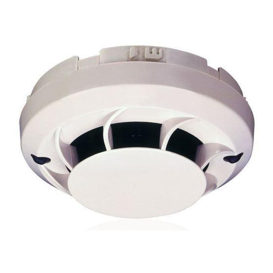
102 mm
B501AP
INSTALLATION AND MAINTENANCE
INSTRUCTIONS FOR MODEL TC806E(I)S1012
ENGLISH
PHOTO ELECTRONIC SMOKE SENSOR
GENERAL DESCRIPTION
Models TC806ES1012 and TC806EIS1012 are intelligent plug-in type smoke sensors
that combine a photoelectronic sensing chamber with addressable communications.
These sensors are designed for open area protection and must only be connected to
control panels that use a compatible proprietary communication protocol for monitoring
and control.
The TC806EIS1012 sensor contains an isolator, if installing this version check the panel
documentation for details of how many isolators can be used on a loop.
Two LEDs on each sensor light to provide a local 360
of LEDs are dependent on panel). Remote LED indicator capability is available as an
optional accessory wired to the standard base terminals (again dependent on panel).
SPECIFICATIONS
Operating Voltage Range:
Max. Standby Current (no comm.): 200 µA @24 V and 25
(comm. LED blink enabled - 5 sec) 300 µA @24 V and 25
(Read 16 sec. LED blink 8 sec)
Max. Alarm Current (LED on):
Operating Humidity Range:
Isolator Characteristics (TC806EIS1012 Only): see S00-7300
Independently tested and certified to: EN54-7: 2000 (and EN54-17: 2005 for EIS)
WIRING GUIDE
Refer to the installation instructions supplied with the plug-in sensor bases for wiring
details. All bases are provided with terminals for power and an optional Remote Indicator.
Note 1: All wiring must conform to applicable local and national codes and regulations.
Note 2: Verify that all sensor bases are installed and that polarity of the wiring is correct
at each base.
Disconnect loop power before installing sensors. Notify proper authorities.
SENSOR INSTALLATION
1. Set the sensor address (see figure 1) by turning the two rotary switches on the
underside of the sensor, selecting a number between 01 and 159. (Note: The
number of addresses available will be dependent on panel capability, check the panel
documentation for information on this). Record the address on the label attached
to the base.
Figure 1: Rotary Address Switches
X 10
2. Insert the sensor into the base and rotate it clockwise until it locks into place.
3. After all the sensors have been installed, apply power to the system.
4. Test the sensor as described under TESTING.
5. Reset the sensor by communication command from the panel.
Tamper-Resistance.
These sensors includes a feature that, when activated, prevents removal of the sensor
from the base without the use of a tool. Refer to the installation instructions for the
sensor base for details of how to use this feature.
Dust covers help to protect units during shipping and when first installed.
They are not intended to provide complete protection against contamination
therefore sensors should be removed before construction, major re-decoration
or other dust producing work is started. Dust covers must be removed before
system can be made operational.
H200-200-00
Honeywell Building Solutions, Honeywell House, Arlington Business Park, Bracknell, Berkshire, RG12 1EB, UK
TC806E(I)S1012
70°C
97 g
-30°C
visible sensor indication (operation
o
see S00-7300
C
o
C
o
220 µA @24 V and 25
C
o
add 50 µA for EIS Isolated
add 3.5 mA @ 24 V and 25
C
o
10% to 93% Relative Humidity, Non-Condensing
WARNING
X 1
CAUTION
DOP-IFD164 TC806ES1012
DOP-IFD165 TC806EIS1012
0786 09
EN54-7: 2000, EN54-17: 2005 (EIS only)
Figure 2: Cleaning the Sensor
Cover Removal Tabs
Sensing Chamber Cover
Sensing Chamber
MAINTENANCE
Before cleaning, disable the system to prevent unwanted alarms:
1. Remove the sensor to be cleaned from the system.
2. Gently release each of the four cover removal tabs that hold the cover in place (see
figure 2) and remove the sensor cover.
3. Vacuum the outside of the screen/chamber cover carefully without removing it.
4. Remove the screen/chamber cover assembly by pulling it straight out.
5. Use a vacuum cleaner and/or clean, compressed air to remove dust and debris from
the sensing chamber and sensing chamber cover.
6. Re-install the sensing chamber cover by aligning the square and round holes on the
cover with the square and round pins around the sensing chamber, gently pressing
it home until it slips into place (Note: Arrows on the plastic indicate the positioning
when replacing the chamber cover and air guide.
7. Re-install the sensor cover. Use the cover removal tabs and LEDs to align the cover
with the sensor. Snap the cover into place.
8. When all sensors have been cleaned, restore power to the loop and test the sensor(s)
as described under TESTING.
TESTING
Sensors must be tested after installation and following periodic maintenance. Disable
the zone or system undergoing maintenance to prevent unwanted alarms.
Test the sensors as follows:
Magnet Method
1. Test the sensor by positioning the test magnet (model M02-04-00 optional) against
the sensor body approximately 2cm from LED 1, indicated by a mark on the sensor
cover as shown in figure 3.
2. Both LED's on the sensor should latch into alarm within 30 seconds, activating the
control panel.
Figure 3: Test Magnet Position
Smoke Method
1. Using generated smoke, or synthetic smoke aerosol from an approved manufacturer
such as No Climb Products Ltd, subject the sensor to controlled amounts of smoke
in accordance with local codes of practice and manufacturer recommendations.
2. Both LED's on the sensor should latch into alarm within 30 seconds, activating the
control panel.
After completion of the test notify the proper authorities that the system is operational.
LIMITATIONS OF SMOKE SENSORS
Smoke sensors must be used in conjunction with compatible equipment.
Smoke sensors will not sense fires which start where smoke does not reach the sensors.
A sensor may not detect a fire developing on another level of a building.
Smoke sensors also have sensing limitations. Consideration must be made of the
environment when selecting fire sensors.
Smoke sensors cannot last forever. Smoke sensors contain electronic parts. Even
though sensors are made to last over 10 years, any of these parts could fail at any
time. Therefore, test your smoke detection system at least semi-annually. Clean and
take care of your smoke sensors regularly. Taking care of the fire detection system you
have installed will significantly reduce your product liability risks.
Honeywell Control Systems Ltd
Honeywell House, Arlington Business Park
Bracknell, Berkshire, RG12 1EB, UK
Sensor Cover
and Screen
LED 2
Mark on Cover
Test Magnet
LED 1
WARNING
I56-3422-004
Advertisement

Related Manuals for Honeywell TC806ES1012


Summary of Contents for Honeywell TC806ES1012
- Page 1 Dust covers must be removed before system can be made operational. H200-200-00 Honeywell Building Solutions, Honeywell House, Arlington Business Park, Bracknell, Berkshire, RG12 1EB, UK I56-3422-004...
- Page 2 La corretta manutenzione del sistema antipolvere prima della messa in funzione del sistema. di rilevazione di incendio installato riduce significativamente i rischi di responsabilità. H200-200-00 Honeywell Building Solutions, Honeywell House, Arlington Business Park, Bracknell, Berkshire, RG12 1EB, UK I56-3422-004...
- Page 3 Las fundas protectoras deben extraerse antes de la puesta en marcha del sistema de detección de incendio reducirá significativamente los riesgos en cuanto a sistema. su responsabilidad con el producto. H200-200-00 Honeywell Building Solutions, Honeywell House, Arlington Business Park, Bracknell, Berkshire, RG12 1EB, UK I56-3422-004...
- Page 4 Bauteile jederzeit ausfallen. Testen Sie deshalb mindestens halbjährlich Ihr die Melder vor Beginn von Konstruktions-, umfangreichen Dekorationsarbeiten Meldersystem. Reinigen und inspizieren Sie die Brandmelder regelmäßig. Inspektionen des Brandmeldesystems reduzieren erheblich das Produkthaftungsrisiko. H200-200-00 Honeywell Building Solutions, Honeywell House, Arlington Business Park, Bracknell, Berkshire, RG12 1EB, UK I56-3422-004...