Table of Contents
Advertisement
Quick Links
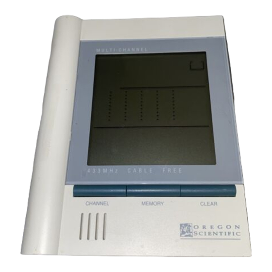
Deluxe In/Out Remote Thermometer
with Trend Chart
MODEL: JTR-168LR
USER'S MANUAL
INTRODUCTION
Congratulations on your purchase of the JTR-168LR Deluxe In/
Out Remote Thermometer.
The basic package comes with a main unit (the temperature
station) and a remote unit (the thermo sensor). The main unit can
support up to three remote units.
The JTR-168LR is easy to use. The main unit has a large display
for the outdoor temperatures, temperature variance for the last 12
hours and the indoor temperatures.
Additional features include ice warning and maximum/ minimum
temperatures for indoors and outdoors.
No wire installation is required between the main unit and the
remote units. As the JTR-168LR operates at 433MHz, it can be
used in the U.S. and most places in Continental Europe.
1
Advertisement
Table of Contents

Related Manuals for Oregon Scientific JTR-168LR


Summary of Contents for Oregon Scientific JTR-168LR
- Page 1 Deluxe In/Out Remote Thermometer with Trend Chart MODEL: JTR-168LR USER'S MANUAL INTRODUCTION Congratulations on your purchase of the JTR-168LR Deluxe In/ Out Remote Thermometer. The basic package comes with a main unit (the temperature station) and a remote unit (the thermo sensor). The main unit can support up to three remote units.
-
Page 2: Main Features
MAIN FEATURES A. OUTDOOR TEMPERATURE Displays current temperature of remote sensor unit. B. TEMPERATURE TREND CHART Outdoor CHANNEL 1 temperature variance display, last 12 hours. C. INDOOR TEMPERATURE Shows the collected indoors temperature D. ICE WARNING ICON Lights up when the ice warning function is active E. - Page 3 L. ANTENNA Receives radio signal from remote unit M. TABLE STAND For standing the main unit on a flat surface N. WALL-MOUNT RECESSED HOLE For mounting the main unit on a wall O. LOW BATTERY INDICATOR - Appears on the 1st Line indicates the battery power of the remote sensor in display is low - Appears on the 3rd Line indicates the battery power of the main unit is low...
- Page 4 HINTS FOR BEST OPERATION • Assign different channels to different remote units. • Insert batteries for remote units before doing so for the main unit. • Set the main unit and the remote thermo-sensor unit within an effective range of 100 meters. •...
-
Page 5: Getting Started
3. Replace the battery compartment door. 4. Flip open the table stand and press the [RESET] button with a blunt stylus. It ensures easier synchronization between the trans- mission and reception of signals. Replace the batteries when the indicator [ perature lights up. -
Page 6: Maximum And Minimum Temperatures
If more than one remote sensor is being used, the unit can auto- matically scan all three of the outdoor channels. To use the automatic outdoor channel scanner function: Press and hold [CHANNEL] for about 2 seconds. The unit will begin a cycle of continuously rotating through the three channels. -
Page 7: Low Battery Warning
HOW TO READ THE TEMPERATURE TREND CHART The temperature variance for CHANNEL 1 for the past 12 hours is automatically scanned on the screen in six equal columns. The variance is represented in rows of degrees C above or below the current temperature at 0 Hr (current time) and 0 C (no vari- ance). -
Page 8: The Reset Button
Main Unit Table Stand Wall Mount Remote Unit Table Stand Wall Mount THE RESET BUTTON The RESET button is used to enhance synchronization of signals after battery replacement or when the unit is operating in an unfavorable way or malfunctioning. Use a blunt stylus to hold down the button. -
Page 9: Specifications
SPECIFICATIONS Temperature Measurement Main Unit Indoor Temperature measurement Proposed operating range : -5.0 C to +50.0 C (23.0 F to 122.0 F) Temperature resolution : 0.1 C (0.2 F) Diagram temperature scale -7 C to Ice Warning function : -2 C to +3 C (Channel-1 Remote Sensor) (28.4 F to 37.4 F) Remote Sensor Unit... - Page 10 Reorient or relocate the receiving antenna. Increase the separation between the equipment and receiver. Connect the equipment into an outlet on a circuit different from that to which the receiver is needed. Consult the dealer of an experienced radio/TV technician for help.