Motorola WE800G User Manual
Wireless ethernet bridge
Hide thumbs
Also See for WE800G:
- User manual (78 pages) ,
- Troubleshooting (5 pages) ,
- Specifications (2 pages)
Table of Contents
Advertisement
Quick Links
Advertisement
Table of Contents

Related Manuals for Motorola WE800G


Summary of Contents for Motorola WE800G
- Page 1 User Guide Wireless Ethernet Bridge WE800G...
- Page 2 Connect the equipment into an outlet on a circuit different from that to which the receiver is connected. • Consult the dealer or an experienced radio/TV technician for help. CAUTION: Changes or modifications not expressly approved by Motorola for compliance could void the user’s authority to operate the equipment.
-
Page 3: Fcc Certification
Motorola, Inc., Broadband Communications Sector, 101 Tournament Drive, Horsham, PA 19044, 1-215-323-1000, declares under sole responsibility that the WR850G, WE800G, WA840G, WN825G, WPCI810G, and BR700 comply with 47 CFR Parts 2 and 15 of the FCC Rules as a Class B digital device. This device complies with Part 15 of FCC Rules. -
Page 4: Table Of Contents
Contents Section 1:Overview _______________________ 1-1 Features ... 1-2 Understanding your User Guide ... 1-2 Box Contents ... 1-3 Understanding Functions ... 1-3 Wireless Ethernet Bridge Connectivity ...1-3 TCP/IP...1-4 Static IP Address...1-4 Dynamic IP Address...1-4 Understanding Wireless ...1-4 Wireless Range...1-5 Recommended Wireless Environment ...1-5 Type of Networks... - Page 5 Hardware Solutions...4-1 Software Solutions...4-3 I cannot access the Configuration Utility for the unit..4-3 My WE800G cannot associate with the wireless access point/router ...4-4 I would like to see if my Internet connection is alive...4-4 Section 5:Glossary _______________________ 5-1 CONTENTS...
-
Page 6: Section 1:Overview
Section 1:Overview Congratulations on purchasing the Motorola Wireless Ethernet Bridge WE800G. With this unit, you have entered the world of freedom and independence – freedom from wires and the independence to communicate wherever YOU choose. The WE800G is built with both the popular 802.11b wireless standard and the new nearly 5-times-faster 802.11g standard, providing you... -
Page 7: Features
CD-ROM based Installation Wizard for easy installation Built-in Web interface for easy configuration Firmware upgrade to stay current with latest specification Your Motorola WE800G Wireless Ethernet Bridge enables you to extend your wireless network and increase your productivity. Understanding your User Guide... -
Page 8: Box Contents
Wireless Ethernet Bridge, are you able to create your own private wireless Ad-Hoc network The mechanics behind the connectivity are explained in the following subsections. Antenna Ethernet Cable CD-ROM WE800G Power Power Adapter Cord SECTION 1, OVERVIEW SECTION 1 Base Station Stand... -
Page 9: Tcp/Ip
Internet. IP moves packets of data between nodes while TCP verifies delivery from client to server. Every device you hook up to your wireless router identifies itself with an IP address. You are able to assign devices on your network with either a static or dynamically assigned IP address. -
Page 10: Wireless Range
OVERVIEW Wireless Range The following describes different scenarios for the expected range of the coverage area of the unit. This table is only a guide and coverage varies due to local conditions. Data Rate 54 Mbps 11 Mbps 5.5 Mbps 2 or 1 Mbps Recommended Wireless Environment The following information helps you to achieve the best wireless... -
Page 11: Type Of Networks
WE800G. Some scenarios require additional hardware. Wireless Ethernet Bridge Infrastructure Mode In this mode, the WE800G functions like a bridge, connecting wired Ethernet clients to a wireless network. This is the most likely scenario you will use, because it shares an Internet connection with your laptop or other wireless client. -
Page 12: Wireless Ethernet Bridge Ad-Hoc Mode
Wireless Ethernet Bridge Ad-Hoc Mode This mode is very similar to the Wireless Ethernet Bridge Infrastructure mode, except the WE800G will connect to other client devices using Ad-Hoc mode. One inherent limitation of operating in this mode is that all client devices must be in wireless range of each other, as opposed to a network with an Access Point, where all wireless devices must be in range of the Access Point. -
Page 13: Multiple Clients Mode
SECTION 1 Multiple Clients Mode In this mode, the WE800G connects multiple clients to your network wirelessly. SECTION 1, OVERVIEW OVERVIEW... -
Page 14: Wireless Ethernet Bridge Physical Description
OVERVIEW Wireless Ethernet Bridge Physical Description The following sections describe the physical characteristics of the WE800G. Back of Wireless Ethernet Bridge The following illustration shows the WE800G back panel: Feature Power Receptacle LAN Port Reset Power Power Reset Receptacle Button... - Page 15 SECTION 1 Feature Reset Button Antenna 1-10 Description A dual-function button. It either resets your unit or resets the unit to the default login settings. If the Wireless Ethernet Bridge is experiencing trouble connecting to the Internet, briefly press and release the Reset button to reset the router.
-
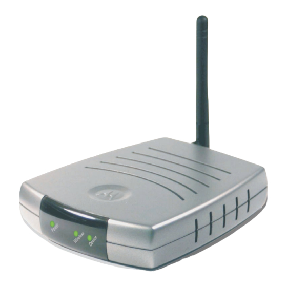
Page 16: Front Of Wireless Ethernet Bridge
OVERVIEW SECTION 1 Front of Wireless Ethernet Bridge The following illustration shows the WE800G front panel: The LEDs of the unit indicate its operational status. SECTION 1, OVERVIEW 1-11... -
Page 17: Led Description
SECTION 1 LED Description The underlined items represent network activity. Condition Color 1. Power Green Green Blinking Blinking/ON 2. Wireless None ON/Blinking Green 3. Device None ON/Blinking Amber Green ON/Blinking 1-12 Status The device is powered on and operating normally. Firmware update is in progress. -
Page 18: Section 2:Installation
Wireless Ethernet Bridge, the threaded knob. Screw the antenna connector (counter-clockwise to remove, clockwise to attach) on to the threaded knob until firmly seated. When attaching, do not over-tighten. Use only the Motorola supplied WE800G power adapter. SECTION 2, INSTALLATION... -
Page 19: Wireless Ethernet Bridge Physical Installation
SECTION 2 Wireless Ethernet Bridge Physical Installation You can install the Wireless Ethernet Bridge in different physical orientations – horizontally, vertically, or hung on the wall. Your own needs determine the best placement. Horizontal Installation To install the Wireless Ethernet Bridge horizontally, as shown in the illustration below: Place the Wireless Ethernet Bridge in the desired location. -
Page 20: Vertical Installation
INSTALLATION Vertical Installation To install the Wireless Ethernet Bridge vertically, as shown in the illustration below: Insert the Wireless Ethernet Bridge into the supplied base. Ensure that the antenna’s location is on top, because the antenna prevents the unit from fitting into the base. The Wireless Ethernet Bridge’s foot slides snugly into the base to keep the unit stable. - Page 21 Be sure you print the template at 100% scale and that Fit to page is not checked in the Print dialog box. SECTION 2, INSTALLATION 3.15 [80.00] MODEL WE800G INPUT VOLTAGE: +5VDC, 2A PART NUMBER: AAAAAA-BBB-CC FCC ID: F2NWE800G S/N: PPPPMMYJJJSSSSSCAABBCCCC...
- Page 22 INSTALLATION Click OK to print the template. Measure the printed template with a ruler to ensure that it is the correct size. Use a center punch to mark the center of the holes on the wall. On the wall, locate the marks for the mounting holes you just made.
-
Page 23: Electrical Connection To Wireless Ethernet Bridge
Plug the power adapter into a grounded and surge protected power outlet. The Power LED on the front panel lights green when connected properly. SECTION 2, INSTALLATION Use only the Motorola supplied WE800G power adapter. To power supply (5V / 2A) INSTALLATION... -
Page 24: Easy Software Setup
INSTALLATION Easy Software Setup Run the Installation Wizard program from the supplied CD-ROM to quickly setup your network. Once your network is up and running, refer to Section 3:Configuration for advanced configuration. Manual Software Setup If you’d prefer to manually setup your network, use this section to configure it. -
Page 25: Wired Connection To Wireless Ethernet Bridge
SECTION 2 Wired Connection to Wireless Ethernet Bridge This section applies if you are connecting your PC with an Ethernet cable to the Wireless Ethernet Bridge. Your PC must be installed first with an Ethernet adapter. You need the supplied Ethernet cable to connect the PC to the Wireless Ethernet Bridge. -
Page 26: Configure Your Computers
INSTALLATION Configure Your Computers For initial configuration, you need to initially configure the PC’s network setting to specify a static IP address for the computer that is going to “talk” to the Ethernet Bridge. After initial configuration: If using DHCP If not using DHCP This section includes information on configuring computers with the following operating systems:... -
Page 27: Configuring Windows 98Se And Me
SECTION 2 Configuring Windows 98SE and ME Click Start. Select Settings > Control Panel. Double-click Network. The Network window is displayed: On the configuration tab, select the TCP/IP line the for the appropriate Ethernet adapter. There might be multiple adapters installed – choose only the one that is configured for your adapter. - Page 28 INSTALLATION Click Properties. The TCP/IP Properties window is displayed: Click the IP address tab. Enter 192.168.30.1 into the IP Address field. Enter 255.255.255.0 into the Subnet Mask field. Click OK. 10 Click the Gateway tab and check to make sure that the Installed Gateway field is blank.
-
Page 29: Windows 98 And Me Dhcp Server Configuration
SECTION 2 Windows 98 and ME DHCP Server Configuration After your initial configuration has been completed, you may need to setup your PC for using a DHCP server, using the procedure below. Follow Steps 1 through 6 from above. Windows 98SE Select Obtain an IP address automatically. - Page 30 INSTALLATION Double-click Local Area Connection. Click the Properties button. Ensure the box next to Internet Protocol (TCP/IP) is selected. SECTION 2, INSTALLATION SECTION 2 2-13...
- Page 31 SECTION 2 Click to highlight Internet Protocol (TCP/IP) and click the Properties button. Enter 192.168.30.10 into the IP Address field. 10 Enter 255.255.255.0 into the Subnet Mask field. 11 Click OK twice to exit and save your settings. 12 Restart your computer to save your settings. 13 Proceed to the Configure Your Wireless Settings section to set up the security settings.
-
Page 32: Windows 2000 Dhcp Server Configuration
INSTALLATION Windows 2000 DHCP Server Configuration After your initial configuration has been completed, you may need to setup your PC for using a DHCP server, using the procedure below. Follow Steps 1 through 8 from above. Select Obtain an IP address automatically. Click OK and then complete the procedure by following steps 11 and 12. - Page 33 SECTION 2 Double-click Local Area Connection. The Local Area Connection Status window appears. Click the Properties button. Ensure the box next to Internet Protocol (TCP/IP) is selected. 2-16 SECTION 2, INSTALLATION INSTALLATION...
- Page 34 INSTALLATION Click to highlight Internet Protocol (TCP/IP) and click the Properties button. Enter 192.168.30.10 into the IP Address field. 10 Enter 255.255.255.0 into the Subnet Mask field. 11 Click OK twice to exit and save your settings. 12 Proceed to the Configure Your Wireless Settings section to set up the security settings.
-
Page 35: Windows Xp Dhcp Server Configuration
SECTION 2 Windows XP DHCP Server Configuration After your initial configuration has been completed, you may need to setup your PC for using a DHCP server, using the procedure below. Follow Steps 1 through 8 from above. Select Obtain an IP address automatically. Click OK and then complete the procedure by following step 11. -
Page 36: Configure Your Wireless Security Settings
Wireless Ethernet Bridge’s default IP address) and press Enter. The login screen will appear: Enter the USER ID. The default factory setting is “admin”, without the quotation marks. Enter the PASSWORD. The default factory setting is “motorola”, without the quotation marks. SECTION 2, INSTALLATION SECTION 2... -
Page 37: Wireless Security Setup
SECTION 2 After you have logged in, for security reasons, you should change the User ID and Password. See Wireless Security Setup. Click the LOG IN button to enter the Wireless Ethernet Bridge’s Web-based Configuration Utility. Wireless Security Setup Follow these procedures to setup the correct security protocols for your Wireless Ethernet Bridge. -
Page 38: Section 3:Configuration
The login screen appears. Enter the USER ID. The default factory setting is “admin”, without the quotation marks. Enter the PASSWORD. The default factory setting is “motorola”, without the quotation marks. Click LOG IN to enter the Wireless Ethernet Bridge’s Web-based Configuration Utility. -
Page 39: Navigation
SECTION 3 Navigation Each of the following subsections provides descriptions for the components of the Wireless Ethernet Bridge’s Configuration Utility – accessible from a web browser. These sections include: Site Survey Wireless Profile 1 Wireless Profile 2 Control Panel To navigate, click on a major section and then the associated subsection. -
Page 40: Active Profile And Site Monitor
CONFIGURATION Active Profile and Site Monitor These screens enable you to configure your Wireless Ethernet Bridge for different wireless scenarios and to search for Access Points (APs). Active Profile Site Monitor Site Survey – Active Profile This is the first screen that appears when logging into the web-based utility. -
Page 41: Site Survey - Site Monitor
SECTION 3 Site Survey – Site Monitor This screen displays information about wireless Access Points (AP) and stations, and their associated information. The settings displayed here help you to configure the Ethernet Bridge appropriately. To access the screen, click Site Survey > Site Monitor. Click APPLY to save your settings or CANCEL to cancel changes. -
Page 42: Configuring Wireless Profile 1 Or 2
CONFIGURATION Configuring Wireless Profile 1 or 2 The Wireless Profile 1 or 2 screens enable you to adjust settings for your wireless connection for a specific wireless profile. Refer to each subsection for further descriptions. These include: Basic Security Advanced Professional Wireless –... -
Page 43: Wireless - Security
SECTION 3 Wireless – Security This screen enables wireless security settings. Some fields activate other options. Refer to the descriptions for details. To access the screen, click Wireless Profile 1 or 2 > Security. Click APPLY to save your settings or CANCEL to cancel changes. Field SSID Broadcast Description... - Page 44 (provides 4 Keys) WEP128 Wired Equivalent Privacy - 128-bit strength (provides 2 Keys) Select the option that best matches your needs. Motorola recommends using WEP128 because it provides a stronger security algorithm. The default is None. SECTION 3, CONFIGURATION SECTION 3...
- Page 45 Enter the Passphrase to be used for Key encryption. This is the Passphrase used by other Access Points (AP), so you must enter the same phrase for all of the Motorola client devices on your wireless LAN. The Passphrase must be between 8 and 63 characters.
- Page 46 Encryption Status fields. You are selecting one of the Key Content fields below. The Key selected here must match between the WE800G and the AP in Infrastructure mode and other clients in Ad-Hoc mode. For example, if you select Key 1 here you have to match Key 1 of the AP.
-
Page 47: Wireless - Advanced
SECTION 3 Wireless – Advanced This section enables you to turn on and off your wireless network and adjust wireless parameters. Generally, the settings here should remain at their default values. To access screen, click Wireless Profile 1 or 2 > Advanced. Click APPLY to save your settings or CANCEL to cancel changes. -
Page 48: Wireless - Professional
CONFIGURATION Wireless – Professional This section enables you to turn on and off your wireless network and adjust wireless parameters. Generally, the settings here should remain at their default values. To access screen, click Wireless Profile 1 or 2 > Professional. Click APPLY to save your settings or CANCEL to cancel changes. - Page 49 802.11b network on the same channel Frame Bursting enables you to send more frames (collection of packets) within a given time period. This feature works with other Motorola products to increase performance throughput. The default is disabled. SECTION 3, CONFIGURATION CONFIGURATION...
-
Page 50: Configuring Control Panel Settings
CONFIGURATION Configuring Control Panel Settings The Control Panel screens enable administrative maintenance for your Wireless Ethernet Bridge, such as changing your User Name/Password, updating your firmware, or backing up your configuration. The following screens are available in Control Panel: Network Address Device Security Firmware Update Configuration Data... -
Page 51: Control Panel - Device Security
SECTION 3 Field Connection Mode Connection Status IP Address Subnet Mask Gateway IP Control Panel – Device Security This screen enables you to change your User ID and password and enables you to manage your Wireless Ethernet Bridge remotely. To access the screen, click Control Panel > Device Security. Click APPLY to save your settings or CANCEL to cancel changes. -
Page 52: Control Panel - Firmware Update
Wireless Ethernet Bridge’s web based utility. It cannot be longer than 63 bytes. A blank password is not allowed. The default is “motorola”. Re-enter the Login Password. The amount of idle time (no actions occur) that elapses before the Wireless Ethernet Bridge automatically logs off the user. -
Page 53: Control Panel - Configuration Data
SECTION 3 Click Control Panel > Firmware Update. Locate the file you downloaded, by typing the path to the file or clicking Browse and navigating to it. Click UPDATE to update the Wireless Ethernet Bridge with the selected firmware file. The Wireless Ethernet Bridge will inform you that you successfully updated the unit. - Page 54 Section 4:Troubleshooting This section details possible solutions to problems that might occur when using the Wireless Ethernet Bridge WE800G. Contact Us If you are unable to locate a solution here, please access our website www.motorola.com/broadband/networking You can also reach us 7 days a week, 24 hours a day at 1-877-466-8646.
-
Page 55: Section 4:Troubleshooting
Check the System Tray at the bottom right of your display to see an icon that looks like a monitor. see the status of your WE800G. Also in Start > Settings > Control Panel > Network and Dial-Up Connections, you can examine the state of your Ethernet connection with the WE800G. -
Page 56: Software Solutions
IP address. The default IP address of WE800G is 192.168.30.1. If after initial set up, the PC that’s used to configure the WE800G has been assigned a different IP address by DHCP or assigned a different static IP address which is not on the same 192.168.30.x... -
Page 57: My We800G Cannot Associate With The Wireless Access Point/Router
Section 2: Configure Your Wireless Security Settings describes how to adjust security settings. Some of the key settings are: The WE800G must be set to match the wireless access point/wireless router for those settings As a suggestion, it may be easier to set the wireless access point/wireless router’s security to open system and no encryption... - Page 58 You can verify the ISP’s IP by referring to documentation that came with your wireless access point/wireless router. If you do NOT receive a reply, try from a different computer to verify that the first PC is not the cause of the problem.
- Page 59 Section 5:Glossary Access Point (AP) A device that provides wireless LAN connectivity to wireless clients (stations). Adapter A device or card that connects a computer, printer, or other peripheral device to the network or to some other device. A wireless adapter connects a computer to the wireless LAN. Address Translation See NAT.
-
Page 60: Section 5:Glossary
SECTION 5 Client In a client/server architecture, a client is a computer that requests files or services such as file transfer, remote login, or printing from the server. On an IEEE 802.11b/g wireless LAN, a client is any host that can communicate with the access point. Also called a CPE. - Page 61 The DNS lookup table is a distributed Internet database; no one DNS server lists all domain name to IP address matches. Domain Name A unique name, such as motorola.com, that maps to an IP address. Domain names are typically much easier to remember than are IP addresses. See DNS.
- Page 62 SECTION 5 Ethernet The most widely used LAN type, also known as IEEE 802.3. The most common Ethernet networks are 10Base-T, which provide transmission speeds up to 10 Mbps, usually over unshielded, twisted-pair wire terminated with RJ-45 connectors. Fast Ethernet (100Base-T) provides speeds up to 100 Mbps.
- Page 63 GLOSSARY Host In IP, a host is any computer supporting end-user applications or services with full two-way network access. Each host has a unique host number that combined with the network number forms its IP address. Host also can mean: A computer running a web server that serves pages for one or more web sites belonging to organization(s) or individuals A company that provides this service...
- Page 64 SECTION 5 Internet Service Provider Local Area Network. A local area network provides a full-time, high-bandwidth connection over a limited area such as a home, building, or campus. Ethernet is the most widely used LAN standard. MAC Address The Media Access Control address is a unique, 48-bit value permanently saved in the ROM at the factory to identify each Ethernet network device.
- Page 65 GLOSSARY Network Two or more computers connected to communicate with each other. Networks have traditionally been connected using some kind of wiring. A Network Interface Card converts computer data to serial data in a packet format that it sends over the LAN. A NIC is installed in an expansion slot or can be built-in.
- Page 66 SECTION 5 Private IP Address An IP address assigned to a computer on the LAN by the DHCP server for a specified lease time. Private IP addresses are invisible to devices on the Internet. See also Public IP Address. Protocol A formal set of rules and conventions for exchanging data.
- Page 67 GLOSSARY Server In a client/server architecture, a dedicated computer that supplies files or services such as file transfer, remote login, or printing to clients. Also see client. Service Provider A company providing Internet connection services to subscribers. SMTP Simple Mail Transfer Protocol is a standard Internet protocol for transferring e-mail.
- Page 68 SECTION 5 TCP/IP The Transmission Control Protocol/Internet Protocol suite provides standards and rules for data communication between networks on the Internet. It is the worldwide Internetworking standard and the basic communications protocol of the Internet. Tunnel To place packets inside other packets to send over a network. The protocol of the enclosing packet is understood by each endpoint, or tunnel interface, where the packet enters and exits the network.
- Page 69 GLOSSARY VoIP Voice over Internet Protocol is a method to exchange voice, fax, and other information over the Internet. Voice and fax have traditionally been carried over traditional telephone lines of the PSTN (Public Switched Telephone Network) using a dedicated circuit for each line.
- Page 70 SECTION 5 Wi-Fi Protected Access. A security regimen developed by IEEE for protection of data on a WLAN. World Wide Web. An interface to the Internet that you use to navigate and hyperlink to information. 5-12 SECTION 5, GLOSSARY GLOSSARY...
- Page 71 Visit our website at: www.motorola.com/broadband 494160-001 07/03 MGBI...