MSI MS-7392 User Manual
Msi ms-7392 motherboard: user guide
Hide thumbs
Also See for MS-7392:
- User manual (117 pages) ,
- Manual (117 pages) ,
- User manual (121 pages)
Table of Contents
Advertisement
Available languages
Available languages
Advertisement
Table of Contents

Related Manuals for MSI MS-7392


Summary of Contents for MSI MS-7392
- Page 1 P31 Neo Series MS-7392 (V1.X) Mainboard G52-73921X6...
-
Page 2: Trademarks
Alternatively, please try the following help resources for further guidance. Visit the MSI website for FAQ, technical guide, BIOS updates, driver updates, an d ot h er i n f orm at i on: func=faqIndex Contact our technical staff at: http://support.msi.com.tw/... -
Page 3: Safety Instructions
Safety Instructions Always read the safety instructions carefully. Keep this User’s Manual for future reference. Keep this equipment away from humidity. Lay this equipment on a reliable flat surface before setting it up. The openings on the enclosure are for air convection hence protects the equip- ment from overheating. -
Page 4: Fcc-B Radio Frequency Interference Statement
This device complies with Part 15 of the FCC Rules. Operation is subject to the following two conditions: (1) this device may not cause harmful interference, and (2) this device must accept any interference received, including interference that may cause undesired operation. MS-7392... -
Page 5: Weee (Waste Electrical And Electronic Equipment) Statement
WEEE (Waste Electrical and Electronic Equipment) Statement... -
Page 8: Table Of Contents
CONTENTS Copyright Notice ... ii Tradema rks ... ii Revision History ... ii Technical Support ... ii Safety Instructions ... iii FCC-B Radio Frequency Interference Statement ... iv WEEE (Waste Electrical and Electronic Equipment) Statement ... v English ... En-1 Specifications ... -
Page 9: English
P31 Neo Series User’s Guide English En-1... -
Page 10: Specifications
Processor Support ® - Intel Core 2 Quad, Core 2 Duo, Pentium Dual-core E2XXX and Celeron 4XX in the LGA775 package (For the latest information about CPU, please visit http://global.msi. com.tw/index.php?func=cpuform) Supported FSB - 1333/ 1066/ 800 MHz Chipset ®... - Page 11 Floppy - 1 floppy port - Supports 1 FDD with 360KB, 720KB, 1.2MB, 1.44MB and 2.88MB Connectors Back panel - 1 PS/2 m ouse port - 1 PS/2 keyboard port - 1 serial port - 4 USB 2.0 Ports - 1 LAN jack - 6 audio jacks On-Board Pinheaders - 1 Parallel port pinheader...
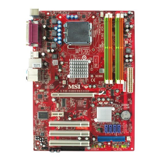
- Page 12 M S-7392 M ainboard En-18 En-18 En-16 En-16 En-17 En-17 En-11 En-11 En-12 Quick Components Guide of P31 Neo Series (MS-7392 v1.X) Mainboard En-4 En-20 En-19 En-20 En-20 En-20 En-20 En-5 En-9 En-7 En-15 En-10 En-15 En-12 En-9 En-9 En-11...
-
Page 13: Central Processing Unit: Cpu
The mainboard uses a CPU socket called Socket 775 for easy CPU installation. If you do not have the CPU cooler, consult your dealer before turning on the com puter. For the latest information about CPU, please visit http://global.msi.com.tw/index.php? func=cpuform Important Overheating Overheating will seriously damage the CPU and system. - Page 14 M S-7392 M ainboard CPU & Cooler Installation Procedures for Socket 775 1. The CPU socket has a plastic cap on it to protect the contact from damage. Before you have installed the CPU, always cover it to pro- tect the socket pin. 2.
-
Page 15: Memory
Memory Specification : 184-pin, 2.5v. 40x2=80 pin DDR2 Specification : 240-pin, 1.8v. Dual channel definition : DIMM slot(s) on Channel A are marked in GREEN color. DIMM slot(s) on Channel B are marked in Orange color. 64x2=128 pin Due to chipset limitations, to enable dual channel mode or single channel mode, installing memory modules should refer to the following table. - Page 16 M S-7392 M ainboard Installing Memory Modules You can find the notch on the memory modules and the volt on the DIMM slots whether DDR or DDR2. Follow the procedures below to install the m emory module properly. 1. The memory m odules has only one notch on the center and will only fit in the right orient ation.
-
Page 17: Connectors, Jumpers, Slots
Connectors, Jumpers, Slots Fan Power Connectors The fan power connectors support system cooling fan with +12V. The CPU FAN supports Smart FAN function. When connect the wire to the connectors, always take note that the red wire is the positive and should be connected to the +12V, the black wire is Ground and should be connected to GND. -
Page 18: Serial Ata/Front Panel/Ieee1394 Connector
M S-7392 M ainboard Serial ATA Connector This connector is a high-speed Serial ATA interface port. Each connector can connect to one Serial ATA device. Important Please do not fold the Serial ATA cable into 90-degree angle. Otherwise, data loss may occur during transmission. Front Panel Connectors These connectors are for electrical connection to the front panel switches and LEDs. - Page 19 Front USB Connector (Yellow) ® This connector, com pliant with Intel necting high-speed USB interface peripherals such as USB HDD, digital cameras, MP3 players, printers, modems and the like. Important Note that the pins of VCC and GND must be connected correctly to avoid possible damage.
- Page 20 M S-7392 M ainboard Front Panel Audio Connector (AC97 Spec) This connector allows you to connect the front panel audio and is compliant with Intel Front Panel I/O Connectivity Design Guide. AUD_MIC AUD_MIC_BIAS AUD_FPout_R HP_ON AUD_FPout_L Important If you don’t want to connect to the front audio header, pins 5 & 6, 9 & 10 have to be jumpered in order to have signal output directed to the rear audio ports.
- Page 21 Infrared Module Connector This connector allows you to connect to infrared module and is compliant with Intel Front Panel I/O Connectivity Design Guide. You must configure the setting through the BIOS setup to use the infrared function. VCC5 IRTX Serial Port Connector This connector is a 16550A high speed com m unication port that sends/receives 16 bytes FIFOs.
-
Page 22: Led Signals
M S-7392 M ainboard D-Bracket™ 2 Connector This connector is for you to connect to the D-Bracket™2 which integrates four LEDs and USB ports. It allows users to identify system problems through 16 various combinations of LED signals. Connected to USB connector Green LED Signal Description... - Page 23 Clear CMOS Jumper There is a CMOS RAM onboard that has a power supply from an external battery to keep the data of system configuration. W ith the CMOS RAM, the system can automatically boot OS every time it is turned on. If you want to clear the system configuration, set the jumper to clear data.
- Page 24 M S-7392 M ainboard ATX 20-Pin Power Connector This connector allows you to connect an ATX 20-pin power supply. To connect the ATX 20-pin power supply, make sure the plug of the power supply is inserted in the proper orientation and the pins are aligned. Then push down the power supply firmly into the connector.
- Page 25 PCI Express Slot (x16/ x4/ x1) The PCI Express slot supports the PCI Express interface expansion card. PCI Express x 4 Slot PCI Express x 1 Slot PCI (Peripheral Component Interconnect) Slot The PCI slot supports LAN card, SCSI card, USB card, and other add-on cards that comply with PCI specifications.
-
Page 26: Back Panel
M S-7392 M ainboard Back Panel Mouse/Keyboard ® The standard PS/2 mouse/keyboard DIN connector is for a PS/2 PS/2 Mouse connector (Green/ 6-pin female) PS/2 Keyboard connector (Purple/ 6-pin female) Parallel Port A parallel port is a standard printer port that supports Enhanced Parallel Port (EPP) and Extended Capabilities Parallel Port (ECP) m ode. - Page 27 DVI Port The DVI (Digital Visual Interface) connector allows you to connect an LCD monitor. It provides a high-speed digital interconnection between the com puter and its display devic e. To connect an LCD m onitor, sim ply pl ug your m onitor cable into the DVI connector, and make sure that the other end of the cable is properly connected to your monitor (refer to your monitor manual for more inform ation.) Important...
- Page 28 M S-7392 M ainboard USB Port The USB (Universal Serial Bus) port is for attaching USB devices such as keyboard, mouse, or other USB-com patible devices. Audio Port Connectors These audio connectors are used for audio devices. You can differentiate the color of the audio jacks for different audio sound effects.
-
Page 29: Bios Setup
BIOS Setup This chapter provides basic information on the BIOS Setup program and allows you to configure the system for optimum use. You may need to run the Setup program when: * An error message appears on the screen during the system booting up, and requests you to run BIOS SETUP. - Page 30 M S-7392 M ainboard Entering Setup Power on the computer and the system will start POST (Power On Self Test) process. W hen the m essage below appears on the screen, press <DEL> key to enter Setup. Press DEL to enter SETUP If the message disappears before you respond and you still wish to enter Setup, restart the system by turning it OFF and On or pressing the RESET button.
- Page 31 The Main Menu ® ® Once you enter AMI or AW ARD BIOS CMOS Setup Utility, the Main Menu will appear on the screen. The Main Menu allows you to select from ten setup functions and two exit choices. Use arrow keys to select among the items and press <Enter> to accept or enter the sub-menu.
- Page 32 Select [Ok] and press Enter to save the configurations and exit BIOS Setup utility. Important The configuration above are for general use only. If you need the detailed settings of BIOS, please see the manual in English version on MSI website. En-24...
-
Page 33: Software Information
Utility m enu - The Utility menu shows the software applications that the mainboard supports. W ebSite menu- The W ebSite menu shows the necessary websites. Important Please visit the MSI website to get the latest drivers and BIOS for better system performance. En-25... -
Page 34: Deutsch
P31 Neo Series Benutzerhandbuch Deutsch De-1... -
Page 35: Spezifikationen
Pro z esso ren ® - Intel Core 2 Quad, Core 2 Duo, Pentium Dual-Core E2XXX und Celeron 4XX Prozerssoren für LGA775 (W eitere CPU Inform ationen finden Sie unter http://global.msi.com. tw/index.php?func=cpuform) FSB(Front-Side-Bus) - 1333/ 1066/ 800 MHz Chipsatz ®... - Page 36 Di sk et te - 1 Disketten Anschluss - Unterstützt 1 Diskettenlaufwerk mit 360KB, 720KB, 1.2MB, 1. 44MB und 2.88MB Anschlüsse Hintere Ein-/ und Ausgänge - 1 PS/2 Mausanschluss - 1 PS/2 Tastaturanschluss Serielle Schnittstelle Anschlüsse - 4 USB 2.0 - 1 LAN Buchse Audiobuchsen On-Board Stiftleiste/ Anschlüsse...
- Page 37 M S-7392 M ainboard De-18 De-18 De-16 De-16 De-17 De-17 De-11 De-11 De-12 Übersicht Eingenschaften der P31 Neo Mainboard Series (MS-7392 v1.X) De-4 De-20 De-19 De-20 De-20 De-20 De-20 De-5 De-9 De-7 De-15 De-10 De-15 De-12 De-9 De-9 De-11 De-9...
-
Page 38: Hauptprozessor: Cpu
Netzteil ausgeschaltet und der Netzstecker gezogen ist, um die Unversehrtheit der CPU zu gewährleisten. Übertakten Dieses Motherboard wurde so entworfen, dass es Übertakten unterstützt. Stellen Sie jedoch bitte sicher, dass die betroffenen Komponenten mit den abweichenden Einstellungen während des Übertaktens zurecht kommen. Von jedem Versuch des Betriebes außerhalb der Produktspezifikationen kann nur abgeraten werden. - Page 39 M S-7392 M ainboard CPU & Kühler Einbau für Sockel 775 1. Der CPU-Sockel besitzt zum Schutz eine Plastikabdeckung. Lassen Sie vor der Installtion diese Schutzkappe auf dem Sockel um Schäden zu verm eiden. 2. Entfernen Sie zuerst die Schutzkappe wie abgebildet in Pfeilrichtung. 3.
-
Page 40: Speicher
Speicher Spezifikation : 184-Pin, 2.5v. 40x2=80 Pin DDR2 Spezifikation : 240-Pin, 1.8v. Dual Channel : Um das Mainboard in Dual Channel betreiben zu können,nutzen Sie die GRÜN (Kanal A) und ORANGE (Kanal B) gefäbten DIMM Bänke parallel. 64x2=128 Pin Wegen der Chipsatzbeschränkungen des P31, beachten Sie folgende Tabelle für den Einsatz des Dual Channel und Single Channel Modus Speicherkombination (SS : einseitige Speicherbestückung, DS : zweiseitige Speicheranordnung,... - Page 41 M S-7392 M ainboard Vorgehensweise beim Einbau von Speicher Modulen Sie finden Kerbe und Strom führung (Volt) sowohl an DDR als auch DDR2 Modulen. B efol g en S i e d i e f ol g en den E i n b auh i n w ei s e, u m d i e D D R / D D R 2 M odu l e ordnungsgemäß...
-
Page 42: Anschlüsse, Steckbrücken Und Slots
Anschlüsse, Steckbrücken und Slots Stromanschlüsse für Lüfter Die Anschlüsseunterstützen aktive Systemlüfter mit + 12V. CPU FAN kann Smart FAN Funktion unterstützen. Wenn Sie den Anschluss herstellen, sollten Sie im mer darauf achten, dass der rote Draht der positive Pol ist, und mit +12V verbunden werden sollte, der schwarze Draht ist der Erdkontakt und sollte mit GND verbunden werden. - Page 43 M S-7392 M ainboard Serial ATA Anschluss An diesen Anschluss können Sie serielle Geräte m it einer Geschwindigkeit von 150 Mbit/s und/oder 300Mbit/s betrieben werden (Abhängig vom Mainboard Chipsatz). Pro Anschluss kann ein S-ATA Gerät angeschlossen werden. Wichtig Bitte falten Sie das Serial ATA Kabel nicht in einem Winkel von 90 Grad, da dies zu Datenverlusten während der Datenübertragung führt.
- Page 44 USB Vorderanschluss (Gelb) Dieser Anschluss entspricht den Richtlinien des Intel bestens geeignet, Hochgeschwindigkeits- USB- Peripheriegeräte anzuschließen, wie z. B. USB Festplattenlaufwerke, Digitalkameras, MP3-Player, Drucker, Modems und ähnliches. Wichtig Bitte beachten Sie, dass Sie die mit VCC (Stromführende Leitung) und GND (Erdleitung) bezeichneten Pins korrekt verbinden müssen, ansonsten kann es zu Schäden kommen.
- Page 45 M S-7392 M ainboard Audioanschluss des Frontpanels (AC97 Spec) Dieser Anschluss erm öglicht den Anschl uss von Audioein- und -ausgängen eines Frontpaneels. Der Anschluss entspricht den Richtlinien des “ Intel Connectivity Design Guide”. AUD_MIC AUD_MIC_BIAS AUD_FPout_R HP_ON AUD_FPout_L Wichtig Wenn Sie die vorderen Audioanschlüsse nicht verwenden, müssen die Pins 5 & 6 und 9 &...
- Page 46 Infrarotmodul Stifleiste Gestattet zu jeder Zeit den Anschluss eines Infrarotmoduls und entspricht den Richtlinien Front Panel I/O Connect ivit y Design Guide. Si e m üssen i m BI OS die ® des Int el notwendigen Einstellungen vornehm en, um die IR Funktion nutzen zu können. VCC5 IRTX Serielle Schnittstelle...
- Page 47 M S-7392 M ainboard D-Bracket™ 2 Anschluss Dieser Anschluss ist, damit Sie an das D-Bracket™ 2 anschließen, das vier LED und USB Tore integri ert. Es erlaubt B enutzern, System P roblem e durc h 16 versc hiedene Kom binationen der LED Signale zu kennzeichnen. Verbindung zur USB Stiftleiste Grün...
- Page 48 Steckbrücke zur CMOS- Löschung Auf dem Mainboard gibt es einen sogenannten CMOS Speicher (RAM), der über eine Batterie gespeist wird und die Daten der Systemkonfiguration enthält. Er ermöglicht es dem Betriebssystem, m it jedem Einschalten automatisch hochzufahren. W ollen Sie die Systemkonfiguration löschen, verwenden Sie hierfür JBAT1 (Clear CMOS Jum per - Steckbrücke zur CMOS Löschung).
- Page 49 M S-7392 M ainboard ATX 20-Pin Stromanschluss Hier können Si e ein ATX 20-Pin Netzteil anschl ießen. W enn Sie die Verbindung herstellen, stellen Sie sicher, dass der Stecker in der korrekten Ausrichtung eingesteckt wird und die Pins ausgerichtet sind. Drücken Sie dann den Netzteilstecker fest in den Steckersockel.
- Page 50 PCI Express Slot (x16/ x4/ x1) Der PCI Express Slot unterstutzt die PCI Express Schnittstelle Erweiterungskarten. PCI Express x 4 Slot PCI Express x 1 Slot PCI (Peripheral Component Interconnect) Slot Di e PCI St eckplät ze unterstützt LAN Karte, SCSI Karte, USB Karte und andere Zusatzkarten cards,die mit PCI Spezifikationen übereinstimmen.
-
Page 51: Hinteres Anschlusspanel
M S-7392 M ainboard Hinteres Anschlusspanel Maus-/Tastatur ® Die Standard PS/2 Maus/Tastatur Stecker Mini DIN ist für eine PS/2® Maus/Tastatur . PS/2 Mausanschluss (Grün/ 6-Pin Buchse) PS/2 Tastaturanschluss (Lila/ 6-Pin Buchse) Parallele Schnittstelle Die Parallele Schnittstelle ist eine Standard Druckerschnittstelle, die ebenso als En- hanced Parallel Port (EPP) und als Extended Capabilities Parallel Port (ECP) betrieben werden kann. - Page 52 DVI Port Der DVI (Digit al Visual I nt erfac e) A nsc hl uss erl aubt I hnen, einen LCD Moni tor anzuschließen. Es stellt eine digitale Hochgeschwindigkeitsverbindung zwischem dem Computer und dem Bildschirm her. Um einen LCD Monitor anzuschließen, verbinden Sie dessen Stecker einfach mit dem DVI Anschluss des Mainboards und stellen Sie sicher, dass das andere Ende des Kabels ordnungsgemäß...
- Page 53 M S-7392 M ainboard USB Port Dieser USB (Universal Serial Bus) Anschluss zum direkten Anschluss von USB- Geräten, wie etwa Tastatur, Maus oder weiterer USB-kom patibler Geräte. Audioschnittstellen Diese Audioanschlüsse werden im Zusamm enspiel m it Audioein-/ ausgabegeräten verw endet . A nhand der Farbe der A udi obuc hsen kann m an unt ersc hi edl i c he Verwendungen unterscheiden.
-
Page 54: Bios Setup
BIOS Setup Dieses Kapitel enthält Informationen über das BIOS Setup und ermöglicht es Ihnen, Ihr System optim al auf Ihre Anforderungen einzustellen. Notwendigkeit zum Aufruf des BIOS besteht, wenn: * W ährend des Bootvorgangs des Systems eine Fehlerm eldung erscheint und Sie zum Aufruf des BIOS SETUP aufgefordert werden. - Page 55 M S-7392 M ainboard Aufruf des BIOS Setups Nach dem Einsc halten beginnt der Com puter den POST (P ower On Self Test - Selbstüberprüfung nach Anschalten). Sobald die Meldung unten erscheint, drücken Sie die Taste <Entf>(<Del>) um das Setup aufzurufen. Press DEL to enter SETUP W enn die Nachricht verschwindet, bevor Sie reagieren und Sie möchten imm er noch ins Setup, starten Sie das System neu, indem Sie es erst AUS- und danach wieder...
- Page 56 Das Hauptmenü ® ® Nachdem Sie das AMI oder AWARD BIOS CMOS Setup Utility, aufgerufen haben, erscheint das Hauptmenü. Es weist zehn Setup- Funktionen und zwei Arten das Menü zu verlassen auf. Verwenden Sie die Pfeiltasten, um im Menü zu navigieren und drücken Sie die Eingabetaste (<Enter>), um ein Unterm enü...
- Page 57 Drücken Sie [okay], um die Konfigurationen speichern und das BIOS Einstellung Dienstprogramm herausnehm en. Wichtig Die Konfiguration oben dienen nur generellen Zwecken. Wenn Sie detaillierte BIOS- Einstellungen benötigen, dann sehen Sie bitte das Handbuch in Englischer Sprache auf der MSI Website ein. De-24 ),, zum der Last...
-
Page 58: Software-Information
Gebrauchsmenmenü - das Gebrauchsmenü zeigt die SoftwareAnwendungen das die mainboard Unterstützungen. W ebSite Menü - das W ebsite Menü zeigt die notwendigen W ebsite. Wichtig Besichtigen Sie bitte die MSI Website, um die neuesten Treiber und BIOS für bessere System Leistung zu erhalten. De-25... -
Page 59: Français
P31 Néo Séries Guide de l’utilisateur Français Fr-1... -
Page 60: Spécificités
La Carte mère MS-7392 Spécificités Processeurs Supportés ® - Intel Core 2 Quad, Core 2 Duo, Pentium Dual-core E2XXX et Celeron 4XX de LGA775 (Pour plus d’informations sur le CPU, veuillez visiter http://global. msi.com.tw/index.php?func=cpuform) FSB Supporté - 1333/ 1066/ 800 MHz Chipset ®... - Page 61 Di squ et te - 1 port de disquette - Supporte 1 FDD avec 360KB, 720KB, 1.2MB, 1.44MB et 2.88MB Connecteurs Panneau arrière - 1 port souris PS/2 - 1 port clavier PS/2 - 1 port serial - 4 ports USB 2.0 - 1 jack LAN - 6 jacks audio connecteurs intégrés...
- Page 62 La Carte mère MS-7392 Fr-18 Fr-18 Fr-16 Fr-16 Fr-17 Fr-17 Fr-11 Fr-11 Fr-12 Guide des composants de P31 Néo Séries La carte mère (MS-7392 v1.X) Fr-4 Fr-20 Fr-19 Fr-20 Fr-20 Fr-20 Fr-20 Fr-5 Fr-9 Fr-7 Fr-15 Fr-10 Fr-15 Fr-12 Fr-9...
-
Page 63: Central Processing Unit: Cpu
CPU, contactez votre revendeur pour vous en procurer un et installet le avant d’allumer l’ordinateur. Pour pl us d’ inform ati ons, veui llez consulter: ht tp:/ /global. msi. com.tw/ index.php? func=cpuform... - Page 64 La Carte mère MS-7392 Procédure d’installation du CPU pour Socket 775: 1. La douille du CPU porte un chapeau en plastique pour la protéger des contacts qui lui causeraient des dom mages. Avant d’installé le CPU, couvrez-le pour protéger la goupille de la douille.
-
Page 65: Mémoire
Mémoire Catacteristique: 184-pin, 2.5v. 40x2=80 pin DDR2 Catacteristique: 240-pin, 1.8v. Définition de double canal : Le(s) slot(s) DIMM sur le canal A sont m arques d’une couleur verte. Le(s) slot(s) DIMM sur le canal B sont marques d’une couleur orange. 64x2=128 pin Etant donne que le chispet est limite, afin d’activer le mode desire (double canal ou canal unique), merci de vous referer aux tableaux ci-dessous pour installer les... - Page 66 La Carte mère MS-7392 Installation des Modules de Mémoire: Vous pouvez trouver l’entaille sur les modules de mémoire et le volt sur les fentes de DIMM pour la DDR ou DDR2. Suivez les procédures ci-dessous pour installer le Module DDR/ DDR2 correctement.
-
Page 67: Connecteurs, Cavaliers, Slots
Connecteurs, Cavaliers, Slots Connecteurs Alimentation du Ventilateur: Les connecteurs au système du ventilateur supportent la puissance du ventilateur avec +12V. Le CPUFAN1 du CPU supporte la fonctione Smart FAN. Quand vous reliez le fil aux connecteurs, notez que le fil rouge est positif et doit être relié au +12V, le fil noir est rectifié... - Page 68 La Carte mère MS-7392 Connecteur Série ATA Le connecteur SATA supporte le port Serial ATA connecteur de SATA peut se connecter à un disque dur. Important Veuillez ne pas tordre le câble Série ATA à90 degrés, cela entraînera la perte de données lors des phases de transfert.
- Page 69 Connecteur USB en façade (Jaune) Ce connecteur est com patible avec IntelR I/O Connectivity Design Guide, pour la connexion de matériels possédant une interface USB tel que: disque dur USB, caméra digitale, imprimante, lecteur MP3 et bien d’autres périphériques. Important Notez que les pins de VCC et de GND doivent être reliés correctement pour éviter des dommages possibles.
- Page 70 La Carte mère MS-7392 Connecteurs Audio panneau en façade (AC97 Spec) Le connecteur vous perm et de connecter l’ audio en façade qui est com patible avec ® l’Intel Front Panel I/O Connectivity Design Guide. AUD_MIC AUD_MIC_BIAS AUD_FPout_R HP_ON AUD_FPout_L Important Si vous ne voulez pas relier à...
- Page 71 Connecteur Module Infrarouge Ce connecteur permet la mise en place d’un module Infrarouge. Vous devez configurer cette fonction dans le BIOS afin de pouvoir l’utiliser. JIR1 est compatible avec l’Intel Front Panel I/O Connectivity Design Guide. VCC5 IRTX Connecteur Port Série Le port série est un port de communication 16550A à...
- Page 72 La Carte mère MS-7392 Connecteur D-Bracket™ 2 Le connecteur est utilisé pour connecter le D-Bracket™ 2. Le D-Bracket est pourvu de 4 LED et ports USB et permet d’identifier les problèmes et ce à l’aide de 16 combinaisons de signaux LED.
- Page 73 Cavalier Évacuer CMOS On observe une RAM de CMOS qui comporte une alimentation d’énergie de la batterie externe pour garder les données de la configuration du systèm e. Avec la RAM de CMOS, le système peut automatiquement initialiser l’OS et il est allum é à chaque fois.
- Page 74 La Carte mère MS-7392 Connecteur Alimentation ATX 20-Pin Ce connecteur vous permet de relier à l’alimentation offerte ATX 20-pin .Pour relier cette alimentation, assurez-vous que la prise d’alimentation d’énergie est insérée dans l’orifice approprié et que les pins sont alignés. Abaissez alors l’alimentation d’énergie.
- Page 75 Slot PCI Express (x16/ x4/ x1) Le slot PCI Express supporte la carte d'extension de l'interface PCI Express. Slot PCI Express x 4 Slot PCI Express x 1 Slot de PCI (Interconnexion Composante Périphérique) Les slots PCI vous permettent d’insérer des cartes d’extension selon vos besoins. Lorsque vous ajoutez ou enlever une carte d’extension, assurez-vous que le PC n’est pas relié...
-
Page 76: Panneau Arrière
La Carte mère MS-7392 Panneau Arrière Connecteur port Souris/ Clavier ® Le connecteur PS/2 souris/clavier DIN est conçu pour brancher un PS/2 clavier. Connecteur PS/2 Souris (Vert / 6-pin féminin) Connecteur PS/2 Clavier(Violet/ 6-pin féminin) Connecteur Port Parallèle : Un port parallèle est un port d’im prim ante standard qui supporte le port parallèle amélioré... - Page 77 Connecteur DVI Le connecteur DVI (interface visuelle numérique) vous perm et de relier un moniteur LCD . Il fournit une interconnexion numérique à grande vitesse entre l’ordinateur et son dispositif d’affichage. Pour relier un moniteur LCD, branchez sim plement votre câble de moniteur au connecteur DVI, et assurez-vous que l’autre extrémité...
- Page 78 La Carte mère MS-7392 Connecteurs USB La racine Serial Universel Autobus d’OHCI (Interface Ouverte de Contrôle du Centre Serveur) sert à attacher des dispositifs d’USB tels que le clavier, souris ou d’autres dispositifs USB-compatibles. Vous pouvez directem ent brancher le dispositif USB au port.
-
Page 79: Configuration Du Bios
Configuration du BIOS Ce chapitre vous informe sur le programme d’installation du BIOS et vous perm et de configurer le systèm e pour un usage optim um . Vous pouvez installer le programm e lorsque: * Un message d’erreur apparaît sur l’écran pendant que le système initialise et vous demande de mettre en marche l’INSTALLATION de BIOS. - Page 80 La Carte mère MS-7392 Frtrer dans le Setup Allumez votre ordinateur, le système lance le processus de POST (Power On Self Test). Quand le m essage ci-dessous apparaît à l’écran, appuyez sur le bouton <DEL> pour entrer dans le setup.
- Page 81 Menu Principal BIOS CMOS Setup Utility, le menu apparaît à ® ® Une fois entré dans le AMI ou AWARD l’écran. Le Menu perm et de sélectionner dix fonctions et deux c hoix de sortie de l’utilitaire. Utilisez les flèches pour vous diriger et utilisez la touche ENTREE pour sélectionner un élément ou entrer dans le sous-menu.
- Page 82 Important Les configurations ci-dessus ne sont que pour l’usage général. Si vous avez besoin d’arrangements détaillés du BIOS, veuillez consulter le manuel (la version française) sur le Web de site de MSI. Fr-24 ) pour accentuer le )servent à accentuer le...
-
Page 83: Information De Logiciel
Menu de services – Il montre les applications logicielles supportées par la carte mère. Le menu du site Web – Il vous indique les sites webs utiles. Important Veuillez consulter le site Web de MSI pour obtenir les derniers pilotes et BIOS pour améliorer l’ exécution du système de votre ordinateur. Fr-25... -
Page 84: Русский
Серия P31 Neo Руководство Пользователя Русский Ru-1... -
Page 85: Характеристики
M S-7392 M ainboard Характеристики Процессор Core 2 Quad, Core 2 Duo, Pentium Dual-core E2XXX и ® - Intel Celeron 4XX в конструктиве LGA775 (Пос леднюю информац ию о поддержк е процессоров мож но п ол у чи т ь н а с ай т е: h t t p : / / gl ob a l . m s i . c om . t w / i n d e x . p h p ? func=cpuform) - 1333/ 1066/ 800 МГц. - Page 86 Фло ппи - 1 флоппи порт - Поддержка 1 FDD с 360KB, 720KB, 1.2MB, 1.44MB и 2.88MB Разъемы Задняя панель - 1 PS/2 порт для подключения мыши - 1 PS/2 порт для подключения клавиатуры - 1 последовательный порт - 4 USB 2.0 порта - 1 LAN разъем...
-
Page 87: Размещение Компонентов Системных Плат P31 Neo
M S-7392 M ainboard Ru-18 Ru-18 Ru-16 Ru-16 Ru-17 Ru-17 Ru-11 Ru-11 Ru-12 Руководство по размещению компонентов системных плат Серии P31 Neo (MS-7392 v1.X) Ru-4 Ru-20 Ru-19 Ru-20 Ru-20 Ru-20 Ru-20 Ru-5 Ru-9 Ru-7 Ru-15 Ru-10 Ru-15 Ru-12 Ru-9 Ru-9... -
Page 88: Центральный Процессор (Cpu
у вас нет процес сорного кулера, пожалуйста, свяж итесь с дилером с целью приобретения и его установки до того, как включите компьютер. Самую последнюю информацию о поддерживаемых процессорах можно получить на сайте http://global.msi.com.tw/index.php?func=cpuform Внимание Перегрев Перегрев может серьезно повредить центральный процессор и систему. - Page 89 M S-7392 M ainboard Установка процессора и вентилятора для Socket 775 1. Р азъем п роц есс ора зак рыт п лас тик овой к рыш к ой, к оторая защищает контакты разъема от повреждений и загрязнений. Если процессор не установлен в разъем, необходимо всегда закрывать его...
-
Page 90: Системная Память
Системная память Спецификация : 184-конт, 2.5v. 40x2=80 конт DDR2 Спецификация : 240-конт, 1.8v. Определение двухканального режима : Слоты DIMM Канала A показаны ЗЕЛЁНЫМ цветом. Слоты DIMM Канала B показаны ОРАНЖЕВЫМ цветом. 64x2=128 pin Из-за ограничений чипсета, чтобы включить оба канала или один канал, следует установить... - Page 91 M S-7392 M ainboard Установка модулей памяти На модулях памяти DDR и DDR2 имеется прорезь, а в разъемах для них - выступ. Для правильной установки модулей памяти выполните действия, перечисленные ниже. 1. Модули памяти имеют только одну прорезь в с ередине. Модуль войдет в разьем...
-
Page 92: Соединители, Перемычки, Разъемы
Соединители, перемычки, разъемы Разъемы питания вентиляторов Разъемы питания вентиляторов поддерживают вентиляторы с питанием +12В. Вентилятор процессора поддерживает функцию Sm art FAN. При подключении необходимо помнить, что красный провод подключается к шине+12В, черный - к земле GND. Ес ли на сис темной п лате установлена мик рос хема апп аратного мониторинга, необходимо... - Page 93 M S-7392 M ainboard Разъем Serial ATA Разъем - это высокоскоростной порт интерфейса Serial ATA. Любой разъем Serial ATA может соединяться с одним устройством Serial ATA. Внимание Избегайте, пожалуйста, резких изгибов кабеля Serial ATA. В противном случае могут возникнуть потери данных при передаче. Коннекторы...
- Page 94 Выносные порты USB 2.0 (Желтый коннектор) Разъем, соответствует спецификации Intel® I/O Connectivity Design, идеально подходит для подключения таких высокоскоростных периферийных устройств, как USB HDD, цифровые камеры, MP3 плееры, принтеры и им подобные. Внимание Помните, что во избежание повреждений, контакты VCC и GND должны быть...
- Page 95 M S-7392 M ainboard Выносной разъем аудио (AC97 Spec) Этот соединитель позволяет подключить выносной разъем аудио на передней панели и совместим с руководством AUD_MIC AUD_MIC_BIAS AUD_FPout_R HP_ON AUD_FPout_L Внимание Если вы не используете выносной аудио разъем, то контакты 5 & 6, 9 & 10 следует...
- Page 96 Коннектор для модуля IrDA Этот позволяет подключить инфракрасный модуль IrDA. Для использования коннектор функции IrDA следует включить ее в настройках BIOS. Эта функция соответствует руководству Intel ® Front Panel I/O Connectivity Design. VCC5 IRTX Коннектор последовательного порта Разъем - это высокоскоростной последовательный порт связи 16550A с 16- битной п...
- Page 97 M S-7392 M ainboard Коннектор для подключения модуля D-Bracket™ 2 Этот коннектор предназначен для подключения модуля D-Bracket™ 2. D-Bracket™ и н т ег р и р у ет ч ет ы р е с в ет од и од а ( L E D ) и U S B п о р т ы . Э т о п оз в ол я ет идентифицировать...
- Page 98 Перемычка очистки CMOS Для сохранения данных о к онфигурац ии с истемы вс троенная память CMOS питается от специальной батарейки. Благодаря памяти CMOS, каждый раз при вк лючении к омп ьютера загружаетс я операционная система. Если требуется очистить память конфигурации системы, установите перемычку очистки CMOS в положение...
- Page 99 M S-7392 M ainboard 20-контактный разъем питания ATX Этот разъем позволяет подключить 20- контактный источник питания ATX. Для подключения источника убедитесь, что его разъем правильно ориентирован, затем острожно вставьте его в ответную часть. Разъем питания ATX 12V (2x2) Этот разъем 12V предназначен для питания CPU. Разъем...
- Page 100 Разъемы PCI Express (x16/ x4/ x1) PCI Express слот поддерживает дополнительные карты расширения интерфейса PCI Express. Разъем PCI Express x 4 Разъем PCI Express x 1 Разъем PCI Разъемы PCI позволяет устанавливать карту LAN, карту SCSI, карту USB и другие доп...
-
Page 101: Задняя Панель
M S-7392 M ainboard Задняя панель Разъемы мыши / клавиатуры Стандартные разъемы m i ni DIN PS/ 2 интерфейсом PS/2 ® Разъем PS/2 для мыши (6-контактная зеленая розетка Разъем PS/2 д л я к лавиатуры (6- контактная пурпурная розетка ) Разъем... - Page 102 Разъем цифрового плоскопанельного монитора Разъем DVI (Цифрового интерфейса видео) позволяет подключить LCD монитор. Он обес п ечи вает выс ок ос к орос тное ц ифр овое с оединен ие к омп ь ютер а и дисплея. Для подключения LCD достаточно подключить кабель к разъему DVI и убедиться, что...
- Page 103 M S-7392 M ainboard Порт USB USB порт (Universal Serial Bus) позволяет подключать такие USB устройства, как клавиатура, мышь и т.д. Аудио разъемы Эти разъемы ис пользуются для п одк лючения звук овых ус тройств. Разъемы, выполняющие разные функции, имеют различные цвета. Выход...
-
Page 104: Настройка Bios
Настройка BIOS В этой главе приводятся основные сведения о режиме настройки BIOS (BIOS SETUP), который позволяет установить оптимальную конфигурацию системы. Этот режим может потребоваться в следующих случаях: * Во время загрузки системы появляется сообщение об ошибке с требованием запустить BIOS SETUP. * Вы... - Page 105 M S-7392 M ainboard Вход в режим настройки Включите питание компьютера. При этом запустится процедура POST (Тест включения питания). Когда на экране появится приведенное ниже сообщение, нажмите клавишу <DEL> для входа в режим настройки. Press DEL to enter SETUP Если сообщение исчезло, а вы не успели нажать клавишу, перезапустите систему, выключив...
- Page 106 Main Menu (Главное меню) При входе в режим настройки BIOS от AMI или AWARD на экране отображается ® ® Главное меню. Главное меню позволяет выбрать десять функций настройки и имеет два варианта выхода. Для перемещения по пунктам используются клавиши со стрелками и <Enter> для подтверждения или входа в подменю. Standard CMOS Features (Стандартные...
- Page 107 ) выберите пункт Save & Exit Setup и нажмите <Enter>, появится следующее сообщение: Выберите [Ok] и нажмите Enter, чтобы сохранить конфигурацию и выйти из BIOS Setup. Внимание Приведенная выше конфигурация подходит для общего применения. Если же вам требуются более тонкие настройки BIOS, обратитесь к английской версии руководства на веб-сайте MSI Ru-24...
-
Page 108: Сведения О Программном Обеспечении
Utility menu (Меню утилит) - Содержит прикладные программы для поддержки системной платы. W ebSite menu (Меню вебсайтов) - Содержит список необходимых вебсайтов. Внимание Приведенная выше конфигурация подходит для общего применения. Если же вам требуются более тонкие настройки BIOS, обратитесь к английской версии руководства на веб-сайте MSI Ru-25...