Table of Contents
Advertisement
Advertisement
Table of Contents

Related Manuals for MSI Hetis G41


Summary of Contents for MSI Hetis G41
- Page 1 Hetis G41 Series MS-6618 (V1.X) Barebone G52-66181X3...
-
Page 2: Copyright Notice
If a problem arises with your system and no solution can be obtained from the user’s manual, please contact your place of purchase or local distributor. Alternatively, please try the following help resources for further guidance. Visit the MSI website for FAQ, technical guide, BIOS updates, driver up- dates and other information: http://global.msi.com.tw/index.php? func=service Contact our technical staff at: http://ocss.msi.com.tw... -
Page 3: Safety Instructions
Safety Instructions Always read the safety instructions carefully. Keep this user’s manual for future reference. Keep this equipment away from humidity. Lay this equipment on a reliable flat surface before setting it up. The openings on the enclosure are for air convection hence protects the equipment from overheating. -
Page 4: Fcc-B Radio Frequency Interference Statement
This device complies with Part 15 of the FCC Rules. Operation is subject to the following two conditions: (1) this device may not cause harmful interference, and (2) this device must accept any interference received, including interference that may cause undesired operation. Micro-Star International Hetis G41 Series... -
Page 5: Weee (Waste Electrical And Electronic Equipment) Statement
WEEE (Waste Electrical and Electronic Equipment) Statement... -
Page 8: Table Of Contents
Copyright Notice...ii Trademarks...ii U.S. Patent Numbers...ii Revision History...ii Technical Support...ii Safety Instructions...iii FCC-B Radio Frequency Interference Statement...iv WEEE (Waste Electrical and Electronic Equipment) Statement...v Chapter 1 Getting Started...1-1 Mainboard Specifications...1-2 Barebone Specifications...1-3 System Configurations...1-4 System Components...1-9 Packing Contents...1-12 Chapter 2 System Information...2-1 System Introduction...2-2 Removing the Cover...2-3 Installing the Hard Disk Drive (HDD)...2-4... -
Page 9: Chapter 1 Getting Started
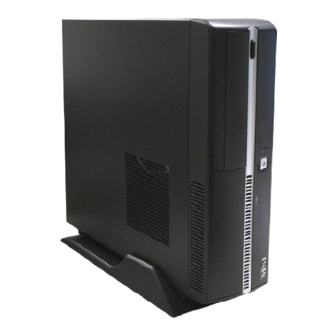
Chapter 1 Getting Started Congratulations for purchasing the Hetis G41 Series (MS-6618) Barebone. This barebone is your best slim PC choice. W ith the fantastic appearance and ultra- small form factor, it can easily be set anywhere. The feature packed platform also gives you an exciting PC... -
Page 10: Mainboard Specifications
M S-6618 Barebone Mainboard Specifications Proce ssor ® - Intel Core 2 Duo/ Quad and Celeron package - 400/ 533/ 667/ 800/ 1066/ 1333 MHz Chipset - North Bridge: Intel - South Bridge: Intel M e mo r y - 2 DDR2 DIMM slots (4 GB Max) (Non-ECC) - Supports DDR2 400/ 533/ 667/ 800 SDRAM (240-Pin/ 1.8 V) - Supports PCI Express LAN 10/ 100/ 1000 Fast Ethernet by Intel 82573L... -
Page 11: Barebone Specifications
Getting Started Barebone Specifications Front Panel - 2 USB ports - 2 audio jacks - 1 IEEE 1394 port (Optional) Back Panel - 1 mouse port - 1 keyboard port - 2 serial ports - 1 VGA port - 1 DVI port - 1 IEEE 1394 port (Optional) - 1 eSATA port - 1 LAN jack... -
Page 12: System Configurations
M S-6618 Barebone System Configuration Front Panel 1. Headphone (Green) This is a connector for headphones or speakers. 2. M icrophone (Pink) This is a connector for microphones. 3. USB Port The USB (Universal Serial Bus) port is for attaching USB devices such as mouse, keyboard, printer, scanner, camera, PDA and other USB-compatible devices. - Page 13 6. HDD LED The HDD LED is on when data is read from or written to the hard disk drive. 7. Eject Button Press the eject button to open and close the optical disk drive. 8. Optical Disk Drive 9. Card Reader Drive * The picture is for your reference only and may slightly vary from the different item you installed.
-
Page 14: Back Panel
M S-6618 Barebone Back Panel 1. Power Jack 2. Ventilation Holes 3. USB Port The USB (Universal Serial Bus) port is provided for attaching USB devices such as mouse, keyboard, printer, scanner, camera, PDA or other USB-compatible devices. 4. PS/2 M ouse Port (Green) ®... -
Page 15: Getting Started
5. PS/2 Keyboard Port (Purple) ® ® The standard PS/2 keyboard DIN connector is for a PS/2 6. Serial Port The serial port is a 16550A high speed communications port that sends/ receives 16 bytes FIFOs. You can attach a serial mouse or other serial devices directly to the connector. -
Page 16: Expansion Slots
M S-6618 Barebone 12. LAN Jack The standard RJ-45 LAN jack is provided for connection to the Local Area Net- work (LAN). You can connect a network cable to it. Activity Indicator Color LED State On (steady state) Left Yellow On (brighter &... -
Page 17: System Components
System Components External View - Detachable bay housing - Multiple ventilation holes - Minimized screw structure 1. CPU Fan Ventilation Holes 3. System Fan Ventilation Holes 5. System Ventilation Holes 7. System Ventilation Holes * Please keep other objects away from the ventilation holes at least 2.5 cm and above. -
Page 18: Internal View
M S-6618 Barebone Internal View (with system thermal solution) 1. Front Panel 3. Mainboard 5. Memory Slot 7. Heat Sink 9. Power Supply Unit 11. Support Bracket * The picture is for your reference only and may slightly vary from the different item you installed. - Page 19 Getting Started (with CPU cooler thermal solution) To prevent the system from overheating, we have adopted a specially designed CPU cooler and multiple ventilation holes for better cooling effects. The following figures illustrate how the system fan effectively exhausts hot air through multiple ventilation holes.
-
Page 20: Packing Contents
M S-6618 Barebone Packing Contents Barebone Stand CPU Cooler Manual Driver/ Utility CD * Please contact us immediately if any of the item is damaged or missing. * The picture is for your reference only and your packing contents may slightly vary depending on the model you purchased. -
Page 21: Chapter 2 System Information
Chapter 2 System Information This chapter provides you with the information about the system setup procedures. Always use grounded wrist strap before holding com- puter components, static electricity may damage the computer components. Always unplug the power cord and telephone line (if modem installed) before inserting any expansion card or module. -
Page 22: System Introduction
M S-6618 Barebone System Introduction The built-in mainboard (MS-7430) is designed for the Hetis G41 Series Barebone (MS-6618) only. Except the mainboard, the built-in components of the barebone include power supply and system fan. In this chapter, we will show you how to install CPU, CPU Cooler, memory module, hard disk drive, optical disk drive and card reader. -
Page 23: Removing The Cover
Removing the Cover Step 1. Unlock the two screws on the back panel. Step 2. Remove the cover. Step 3. Press the level on the support bracket to release it. Step 4. Unlock the screw on the front panel to release the drive bay. System Information... -
Page 24: Installing The Hard Disk Drive (Hdd)
M S-6618 Barebone Installing the Hard Disk Drive (HDD) Step 1. Lift the drive bay to slide aside. Step 2. Pull the HDD tray forwards to remove it from the chassis. Step 3. Put the HDD in the HDD tray and use four screws to fix it on both sides. -
Page 25: Installing The Optical Disk Drive (Odd)
Installing the Optical Disk Drive (ODD) Step 1. Pull the lock brackets outwards on the both sides to release. Step 2. Insert the ODD and push the lock brackets back to fix it. Step 3. Connec t the cable and the power cord to the ODD, then restore the drive bay. -
Page 26: Installing The Card Reader
M S-6618 Barebone Installing the Card Reader Step 1. Use the screwdriver to unlock the card reader bay. Step 2. Insert the card reader into the bay with 15 degree angle. Step 3. Insert the LED into the cage and lock the card reader with two s c rews . -
Page 27: Installing The Memory Module
System Information Installing the Memory Module Step 1. Locate the DIMM slots. Step 2. Insert the DIMM vertically into the slot. Note: The DIMM has only one notch on the center of module. It will only fit in the right direction. -
Page 28: Installing The Cpu
M S-6618 Barebone Installing the CPU Step 1. Locate the CPU socket. Pull t h e l e ver awa y f r om t h e socket and raise it up, then lift up the cover. Step 2. Put the CPU onto the socket. Note: Make sure the pins are com- pletely embedded into the socket. -
Page 29: Installing The Cpu Cooler
Installing the CPU Cooler Step 1. Place the CPU cooler onto the CPU socket and secure the four screws. Important Do not fix any screw until all the four screws are in the position, and lock the four screws with balance, or it may shift the CPU position to cause the system unbootable. -
Page 30: Restoring The Cover
M S-6618 Barebone Restoring the Cover Step 1. Restore the support bracket. Step 2. Restore the cover. St ep 3 . Loc k t he c over wit h th e s c rews . Vertical Type Horizontal Type 2-10... -
Page 31: Installing The Stand
Installing the Stand Step 1. Lift up the PC and put the rubber feet into the pits on the stand. Step 2. Make sure the rubber feet to get stuck on the stand. Step 3. Put the PC on the stand or lay on the rubber foots. -
Page 33: Appendix A Realtek Alc888 Audio
Appendix A Realtek ALC888 Audio The Realtek ALC888 provides 10-channel DAC that si- multaneously supports 7.1 sound playback and 2 chan- nels of independent stereo sound output (multiple streaming) through the Front-Out-Left and Front-Out- Right channels. Realtek ALC888 Audio... -
Page 34: Installing The Realtek Hd Audio Driver
M S-6618 Barebone Installing the Realtek HD Audio Driver You need to install the driver for Realtek ALC888 codec to function properly before you can get access to 2-, 4-, 6-, 8- channel or 7.1+2 channel audio operations. Follow the procedures described below to install the drivers for different operating systems. - Page 35 3. Click Next to install the Realtek High Definition Audio Driver. 4. Click Finish to restart the system. Realtek ALC888 Audio Click here Select this option Click here...
-
Page 36: Software Configuration
M S-6618 Barebone Software Configuration After installing the audio driver, you are able to use the 2-, 4-, 6- or 8- channel audio feature now. Click the audio icon from the system tray at the lower-right corner of the screen to activate the HD Audio Configuration. It is also available to enable the audio driver by clicking the Realtek HD Audio M anager from the Control Panel. -
Page 37: Sound Effect
Realtek ALC888 Audio Sound Effect Here you can select a sound effect you like from the Environment list. Environment Simulation You will be able to enjoy different sound experience by pulling down the arrow, totally 23 kinds of sound effect will be shown for selection. Realtek HD Audio Sound Manager also provides five popular settings “Stone Corridor”, “Bathroom”, “Sewer pipe”, “Arena”... - Page 38 M S-6618 Barebone Equalizer Selection Equalizer frees users from default settings; users may create their owned preferred settings by utilizing this tool. 10 bands of equalizer, ranging from 100Hz to 16KHz. Save The settings are saved permanently for future use. Enable / Disable To disable, you can tem- porarily stop the sound...
- Page 39 Frequently Used Equalizer Setting Realtek recognizes the needs that you might have. By leveraging our long experience at audio field, Realtek HD Audio Sound Manager provides you certain optimized equal- izer settings that are frequently used for your quick enjoyment. [How to Use It] Other than the buttons “Pop”...
- Page 40 M S-6618 Barebone Mixer In the Mixer part, you may adjust the volumes of the rear and front panels individually. 1. Adjust Volume You can adjust the volume of the speakers that you pluged in front or rear panel by select the Realtek HD Audio rear output or Realtek HD Audio front output items.
- Page 41 Important You have to plug audio device into the jacks on the rear and front panel first before enable the multi-stream function. W hen you are playing the first audio source (for example: use W indows Media Player to play DVD/VCD), the output will be played from the rear panel, which is the default setting.
- Page 42 M S-6618 Barebone 3. Playback control Tool Mute M u te You may choose to mute single or multiple volume controls or to completely mute sound output. Tool - Show the following volume controls This is to let you freely decide which volume control items to be displayed. - Advanced controls - Enable playback multi-streaming W ith this function, you will be able to have an audio chat with your friends via...
- Page 43 4. Recording control Tool Mute M u te You may choose to mute single or multiple volume controls or to completely mute sound input. Tool - Show the following volume controls This is to let you freely decide which volume control items to be displayed. - Enable recording multi-streaming Important ALC888 allows you to record the CD, Line, Mic and Stereo Mix channels...
- Page 44 M S-6618 Barebone Audio I/O In this tab, you can easily configure your multi-channel audio function and speakers. You can choose a desired multi-channel operation here. a. Headphone for the common headphone b. 2CH Speaker for Stereo-Speaker Output c. 4CH Speaker for 4-Speaker Output d.
- Page 45 Realtek ALC888 Audio Connector Settings Click to access connector settings. Disable front panel jack detection (option) Find no function on front panel jacks? Please check if front jacks on your system are so-called AC’97 jacks. If so, please check this item to disable front panel jack detection. M ute rear panel output when front headphone plugged in.
- Page 46 M S-6618 Barebone Test Speakers You can select the speaker by clicking it to test its functionality. The one you select will light up and make testing sound. If any speaker fails to make sound, then check whether the cable is inserted firmly to the connector or replace the bad speakers with good ones.
- Page 47 Realtek ALC888 Audio Microphone In this tab you may set the function of the microphone. Select the Noise Suppres- sion to remove the possible noise during recording, or select Acoustic Echo Cancelltion to cancel the acoustic echo druing recording. Acoustic Echo Cancelltion prevents playback sound from being recorded by mi- crophone together with your sound.
-
Page 48: D Audio Demo
M S-6618 Barebone 3D Audio Demo In this tab you may adjust your 3D positional audio before playing 3D audio applica- tions like gaming. You may also select different environment to choose the most suitable environment you like. A-16... - Page 49 Realtek ALC888 Audio Information In this tab it provides some information about this HD Audio Configuration utility, including Audio Driver Version, DirectX Version, Audio Controller & Audio Codec. You may also select the language of this utility by choosing from the Language list. Also there is a selection Show icon in system tray.
-
Page 50: Hardware Setup
M S-6618 Barebone Hardware Setup Connecting the Speakers W hen you have set the Multi-Channel Audio Function mode properly in the software utility, connect your speakers to the correct phone jacks in accordance with the setting in software utility. n 2-Channel M ode for Stereo-Speaker Output Refer to the following diagram and caption for the function of each phone jack on the back panel when 2-Channel Mode is selected. - Page 51 n 4-Channel M ode for 4-Speaker Output 4-Channel Analog Audio Output Line-In Line-Out (Front channels) RS-Out (Rear surround channels) No function No function Realtek ALC888 Audio Back Panel A-19...
- Page 52 M S-6618 Barebone n 6-Channel M ode for 6-Speaker Output 6-Channel Analog Audio Output Line-In Line-Out (Front channels) RS-Out (Rear surround channels) CS-Out (Center and Subwoofer channel) No function A-20 Back Panel...
- Page 53 n 8-Channel M ode for 8-Speaker Output 8-Channel Analog Audio Output Line-In Line-Out (Front channels) RS-Out (Rear surround channels) CS-Out (Center and Subwoofer channel) SS-Out (Side channels) Realtek ALC888 Audio Back Panel A-21...