Table of Contents
Advertisement
Advertisement
Table of Contents

Related Manuals for Cobra 21 LTD ST


Summary of Contents for Cobra 21 LTD ST
- Page 1 21LTDST.MANUAL.REV.QX 9/25/98 10:59 AM Page 1 OPERATING INSTRUCTIONS FOR YOUR 40 CHANNEL CITIZENS BAND 2-WAY MOBILE RADIO Model 21 LTD ST Cobra Electronics Corporation 6500 W. Cortland Street Chicago, IL 60707 PRINTED IN HONG KONG ©COBRAELECTRONICS CORP. 1997 480-221-P-001...
-
Page 2: Table Of Contents
21LTDST.MANUAL.REV.QX 9/25/98 10:59 AM Page 3 How To Use Your Citizens Band 2-Way Mobile Radio Model 21 LTD ST Contents The CB Story ...1 SoundTracker System ...1 Specifications ...2,3 Installation Location...4 Mounting Connections...4, 5 CB Antenna ...6 Ignition Noise Interference ...7 In House Operation...7... -
Page 3: Specifications
21LTDST.MANUAL.REV.QX 9/25/98 10:59 AM Page 5 Specifications FREQUENCY RANGE The COBRA21 LTD ST transceiver represents one of the most advanced AM two- way radios ever designed for use as a Class D station in the Citizens Radio Service. This unit features advanced Phase Lock Loop (PLL) circuitry providing complete coverage of all 40 channels as shown below. -
Page 4: Installation
21LTDST.MANUAL.REV.QX 9/25/98 10:59 AM Page 7 Installation Location Plan the location of the transceiver and microphone bracket before starting the installation. Select a location that is convenient for operation and does not inter- fere with the driver or passengers in the vehicle. In automobiles, the transceiver is usually mounted to the underneath of the dash panel, with the microphone bracket beside it. -
Page 5: Cb Antenna
21LTDST.MANUAL.REV.QX 9/25/98 10:59 AM Page 9 Installation (Cont.) CB Antenna Since the maximum allowable power output of the transmitter is limited by the FCC, the antenna is one important factor affecting transmission distance. Only a properly matched antenna system will allow maximum power transfer from the 50 ohm transmission line to the radiating element. -
Page 6: Operation
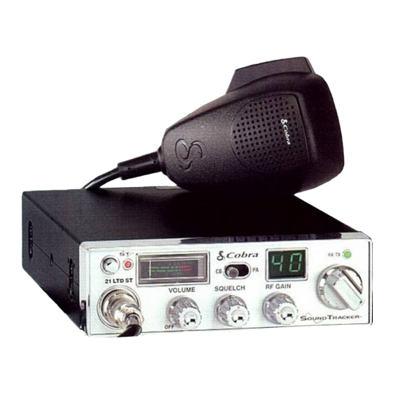
21LTDST.MANUAL.REV.QX 9/25/98 10:59 AM Page 11 Operation Controls and Indicators Refer to controls, indicators and connectors as illustrated below: A. Front Panel MICROPHONE CONNECTOR. Front panel microphone connector. OFF/ON/VOLUME. Turn clockwise to turn power on and set the desired listening volume. SQUELCH. -
Page 7: Operating Procedure To Receive
21LTDST.MANUAL.REV.QX 9/25/98 10:59 AM Page 13 Operation (Cont.) B. Press-To-Talk Microphone Both the receiver and transmitter are controlled by the Press-to-Talk switch on the microphone. Press the switch and the transmitter is activated; release the switch to receive. When transmitting, hold the microphone two inches from the mouth and speak clearly in a normal voice. -
Page 8: Operating Procedure To Transmit
21LTDST.MANUAL.REV.QX 9/25/98 10:59 AM Page 15 Operation (Cont.) Operating Procedure to Transmit Be sure the operator has read and understands part 95, F.C.C. Rules and Regulations prior to operating the transmitter. Select the desired channel. Set the DYNAMIKE control fully clockwise. The receiver and transmitter are controlled by the press-to-talk switch on the microphone. -
Page 9: Maintenance And Adjustment
21LTDST.MANUAL.REV.QX 9/25/98 10:59 AM Page 17 Maintenance and Adjustment The COBRA CB transceiver is specifically designed for the environment encoun- tered in mobile installations. The use of all solid state circuitry and its light weight result in high reliability. Should a failure occur, however, review the following, then if necessary, replace parts only with identical parts. -
Page 10: A Few Rules That Should Be Obeyed
Ship prepaid and insured by way of a traceable carrier (to avoid loss in transit) such as United Parcel Service (UPS), Roadway Parcel Service (RPS) or First Class Insured Mail to Cobra Factory Service, Cobra Electronics Corporation, 6500 W. Cortland St., Chicago, IL60707. Cobra is not respon- sible for units not received if package has not been properly insured. -
Page 11: Limited Two Year Warranty
Mail to: Cobra Accessories Dept. 6500 W. Cortland St., Chicago, IL 60707 Make check or money order (no stamps) payable to Cobra Electronics and mail with this order form to: Cobra Accessories Dept. 6500 W. Cortland St.,Chicago,IL 60707 Call 773-889-3087,or fax 773-622-2269 for credit card orders Allow 4 to 6 weeks for deliver y.