Advertisement
Quick Links
FX INPUT AND OUTPUT TERMINAL BLOCKS
USER'S GUIDE
JY992D50401L
This manual contains text, diagrams and explanations which will guide the reader in the correct installation
and operation of the FX TERMINAL BLOCKS. It should be read and understood before attempting to
install or use the unit. Further information can be found in the FX series PLC hardware manuals.
If in doubt at any stage during the installation of the FX TERMINAL BLOCKS always consult a profes-
sional electrical engineer who is qualified and trained to the local and national standards.
All terminal blocks described in this manual conform to the UL/cUL Standard.
Note's on the symbology used in this manual
At various times through out this manual certain symbols will be used to highlight points of infor-
mation which are intended to ensure the users personal safety and protect the integrity of the
equipment. Whenever any of the following symbols are encountered, its associated note must be
read and understood. Each of the symbols used will now be listed with a brief description of its
meaning.
Hardware warnings
1) Indicates that the identified danger WILL cause physical and property damage.
2) Indicates that the identified danger could POSSIBLY cause physical and property damage.
Guidelines for the safety of the user and protection of the FX TERMINAL BLOCKS
•
This manual has been written to be used by trained and competent personnel. This is defined
by the European directives for machinery, low voltage and EMC.
•
If in doubt at any stage during the installation of the FX TERMINAL BLOCKS always consult a
professional electrical engineer who is qualified and trained to the local and national stan-
dards. If in doubt about the operation or use of the FX TERMINAL BLOCKS please consult
the nearest Mitsubishi Electric distributor.
•
Under no circumstances will Mitsubishi Electric be liable or responsible for any consequential
damage that may arise as a result of the installation or use of this equipment.
•
All examples and diagrams shown in this manual are intended only as an aid to understand-
ing the text, not to guarantee operation. Mitsubishi Electric will accept no responsibility for
actual use of the product based on these illustrative examples.
•
Owing to the very great variety in possible application of this equipment, you must satisfy
yourself as to its suitability for your specific application.
1. INTRODUCTION
Terminal blocks convert I/O terminals of connector type PLC into terminal blocks. Some terminal blocks
directly extend inputs and outputs of PLC. Other terminal blocks are equipped with diversified built-in
devices, and function only as inputs or only as outputs.
INPUT
OUTPUT
MODEL
FX-16E-TB/UL
16 pt (Direct input/output)
FX
FX
FX
FX-32E-TB/UL
32 pt or 16/16 pt (Direct input/output)
FX
FX
FX-16EYR-ES-TB/UL
16 pt (Relay)
FX-16EYS-ES-TB/UL
16 pt (Triac)
FX
16 pt
FX
FX-16EYT-ESS-TB/UL
(Transistor source)
FX
16 pt
FX-16EYT-ES-TB/UL
(Transistor sink)
FX-16EX-A1-TB/UL
16 pt (100V AC)
FX
MODEL
FX-16E-TB
FX-32E-TB
FX-16EYR-TB
FX-16EYT-TB
FX-16EX-A1-TB
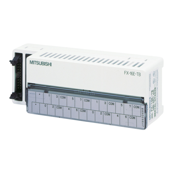
2. EXTERNAL DIMENSION
FX-16E-TB/UL, FX-16E-TB
FX-16EY(: R/T/S)-TB/UL
FX-16EY(: R/T)-TB
FX-16EX-A1-TB/UL, FX-16EX-A1-TB
Accessories
-
Input / output extension block labels
-
Terminal layout cards
3. CONFIGURATION AND OPTIONS
4. CONNECTOR CABLE PIN CONFIGURATION
PLC
( ): Pin No.
X/Y000 (1)
X/Y001 (2)
X/Y002 (3)
X/Y003 (4)
CURRENT
APPLICABLE PLC
CONSUMPTION
X/Y004 (5)
-MT-ESS/UL
2C
X/Y005 (6)
-MT-DSS
2NC
X/Y006 (7)
-EX-DS
2NC
-EYT-DSS
2NC
X/Y007 (8)
-MT-E/UL
2C
COM (9)
80mA (5mA/1pt)
-MT-ESS/UL
2C
-MT-DSS
2NC
The connections required between the FX
112mA (7mA/1pt)
-EYT-DSS
2NC
gram below with an example for inputs X000 to X017 and outputs Y000 to Y017.
The I/O connector should be the 20-pin type and should conform to MIL C 83503 of Military Standard.
-MT-E/UL
48mA (3mA/1pt)
2C
INPUT
OUTPUT
APPLICABLE PLC
16 pt (Direct input/output)
FX
-MT-D/UL
2NC
FX
-EX-D/UL
2NC
32 pt or 16/16 pt (Direct input/output)
FX
-EYT-D/UL
2NC
16 pt (Relay)
FX
-MT-D/UL
2NC
16 pt
FX
-EYT-D/UL
2NC
(Transistor sink)
FX
-MT-D/UL
2NC
16 pt (100V AC)
FX
-EX-D/UL
2NC
FX-32E-TB/UL
FX-32E-TB
STANDARD PRE TERMINATED CABLES
LENGTHS
FLAT CABLES
ROUND CABLES
1.5 m (4.9 ft)
FX-16E-150CAB
FX-16E-150CAB-R
3.0 m (9.8 ft)
FX-16E-300CAB
FX-16E-300CAB-R
5.0 m (16.4 ft) FX-16E-500CAB
FX-16E-500CAB-R
TERMINAL BLOCKS
( ): Pin No.
(1) X/Y000
X/Y010 (11)
(11) X/Y010
(2) X/Y001
X/Y011 (12)
(12) X/Y011
(3) X/Y002
X/Y012 (13)
(13) X/Y012
(4) X/Y003
X/Y013 (14)
(14) X/Y013
(5) X/Y004
X/Y014 (15)
(15) X/Y014
(6) X/Y005
X/Y015 (16)
(16) X/Y015
(7) X/Y006
X/Y016 (17)
(17) X/Y016
(8) X/Y007
X/Y017 (18)
(18) X/Y017
(9) COM
COM (19)
(19) COM
(10)
(10)
(20)
(20)
, FX
main unit and a terminal block are shown in the dia-
2C
2NC
CURRENT
5. TERMINAL WIRING
CONSUMPTION
Never perform external wiring to unused terminals
Note
80mA (5mA/1pt)
✩ Do not lay I/O cables next to power cables or allow them to share the
same trunking duct.
112mA (7mA/1pt)
✩ Where I/O signals are used over an extended distance consideration
must be made for voltage drop and noise interference.
48mA (3mA/1pt)
✩ Use crimp-style terminals of the dimensions shown in the figure below.
✩ Tighten terminals at a torque of 0.5 to 0.8 N·m (4.4 to 7.1 lbf·in). Do not
tighten the terminal block mounting screws with a torque outside the
above-mentioned range. Failure to do so may cause equipment failures or malfunctions.
6. DIRECT INPUT BLOCKS AND DIRECT OUTPUT BLOCKS WIRING
Internal circuit
CN2
(20)
(10)
COM
(19)
(9)
COM
&&7
(18)
(8)
##7
&&6
(17)
(7)
##6
&&5
(16)
(6)
##5
&&4
(15)
(5)
##4
&&3
(14)
(4)
##3
&&2
(13)
(3)
##2
&&1
(12)
(2)
##1
&&0
(11)
(1)
##0
1
0
2
CN1
(20)
(10)
COM
(19)
(9)
COM
&&7
(18)
(8)
##7
&&6
(17)
(7)
##6
&&5
(16)
(6)
##5
&&4
(15)
(5)
##4
&&3
(14)
(4)
##3
&&2
(13)
(3)
##2
&&1
(12)
(2)
##1
&&0
(11)
(1)
##0
1
0
-
(9) and (19) of both CN1 and CN2 are short-circuited internally.
Inputs
PLC
TYPE
Source
(-ve S/S)
FX
-MT-ESS/UL
2C
Sink
(+ve S/S)
FX
-MT-E/UL
2C
FX
-MT-D/UL
Sink
2NC
FX
-EX-D/UL
2NC
Source
FX
-MT-DSS
2NC
FX
-EX-DS
2NC
Sink
. Such wiring may damage the unit.
For M3.5
(0.14in)
FX-32E-TB
&&
0
1 2 3
&&
4
5 6 7
3
COM
5
7
COM
1
3
COM
5
7
COM
COM
4
6
COM
0
2
COM
4
6
COM
FX-16E-TB
&&
0
1 2 3
&&
4
5 6 7
3
COM
5
7
COM
1
3
COM
5
7
COM
2
COM
4
6
COM
0
2
COM
4
6
COM
TYPICAL WIRING
PLC Inputs
COM
1
3
COM
5
7
COM
0
2
COM
4
6
COM
PNP
PLC Inputs
COM
1
3
COM
5
7
COM
0
2
COM
4
6
COM
NPN
PLC Inputs
COM
1
3
COM
5
7
COM
0
2
COM
4
6
COM
PNP
PLC Inputs
COM
1
3
COM
5
7
COM
0
2
COM
4
6
COM
NPN
Advertisement

Related Manuals for Mitsubishi Electric MELSEC-F FX-16E-TB


Summary of Contents for Mitsubishi Electric MELSEC-F FX-16E-TB
- Page 1 All examples and diagrams shown in this manual are intended only as an aid to understand- (-ve S/S) -MT-ESS/UL ing the text, not to guarantee operation. Mitsubishi Electric will accept no responsibility for actual use of the product based on these illustrative examples. 4. CONNECTOR CABLE PIN CONFIGURATION •...
- Page 2 Outputs Relay output blocks FX-16EYR-ES-TB/UL, FX-16EYR-TB wiring Transistor output blocks wiring FX-16EYT-ESS-TB/UL (source) TYPICAL WIRING TYPE 1 2 3 5 6 7 && 1 2 3 && 4 5 6 7 OUTPUT No. A surge absorber is connected to each output. Power supply PLC Outputs for relays...