
Related Manuals for Linksys PC22224


Summary of Contents for Linksys PC22224
-
Page 1: Layer 2 Management
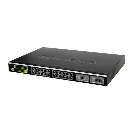
ProConnect ® II Series 2224 Layer 2 Management 24-Port 10/100 Ethernet Switch Use this guide to install: PC22224 User Guide... - Page 2 FIVE years from the date of purchase. If the product proves defective dur- ing this warranty period, call Linksys Customer Support in order to obtain a Return Authorization Number. BE SURE TO HAVE YOUR PROOF OF PURCHASE ON HAND WHEN CALLING.
-
Page 3: Table Of Contents
Changing the Administration Password Changing the Guest Password Statistic Collection Reboot-on-Error Remote Telnet Login ProConnect II 2224 Layer 2 Management 24-Port 10/100 Ethernet Switch ® Series Returning to the Basic Management Screen LAN Port Configuration Changing the Speed and Flow Control... -
Page 4: Introduction
Three Port Trunking groups eliminate bottlenecks, and you can stack up to 8 switches and manage them as one. So when you're ready to bring your network up to speed, get Linksys reliability, manageabili- ty, stackability, and expandability -- with the ProConnect® II 2224 Ethernet Switch. -
Page 5: Getting To Know The Switch
The Console Port The Switch is equipped with a serial port labeled CONSOLE (located on the front of the switch) that allows you to connect to a computer’s serial port (for configuration purposes) using the provided serial cable. n nect II 2224... -
Page 6: The Back Panel
Before you choose a location for the Switch, observe the following guide- lines: • Make sure that the switch is accessible and that the cables can be connect- ed easily. • Keep cabling away from sources of electrical noise, power lines, and fluo- rescent lighting fixtures. -
Page 7: Desk Top Or Shelf Mounting The Switch
3. Connect the other end of the cable to the network device, such as printer server, workstation or router. 4. Connect one end of the power cable to the switch and the other end into a standard electrical outlet. When the Switch receives power, the Power LED will remain solid Green. -
Page 8: Uplinking The Switch
Uplinking the Switch All 24 ports on the Switch can act as uplink ports, allowing you to uplink to other switches or hubs using a standard Ethernet connection. To uplink the switch, connect one end of a Category 5 (or better) network cable into a port, then connect the other end of the cable into the desired net- work device’s uplink port. -
Page 9: Remote Console Management
IP address to the Switch, refer to the Configuring the Switch section. Logging On to the Switch When you log on to the Switch for the first time, a sign-in string appears and you are prompted for a console login name and password. The factory default login name is set as “admin”... -
Page 10: Basic Management Activities
Basic Management Activities After you log on to the Switch, the Switch Management screen will appear. The Switch Management screen consists of a series of menus. Each menu has several options, which are listed vertically. A highlight in each menu lets you select the option you wish to choose;... -
Page 11: Changing The Location
2. Enter a location name. If you make a mistake, use the Backspace key to delete the error. 3. Press Enter to return to the General screen. ProConnect II 2224 Layer 2 Management 24-Port 10/100 Ethernet Switch ® Series Changing the Administration Password 1. -
Page 12: Changing The Guest Password
1. Use the Down Arrow key to highlight guest Password and press the Enter key. The Enter New Password screen will appear. ProConnect II 2224 Layer 2 Management 24-Port 10/100 Ethernet Switch ® Series 2. Enter a new guest password. If you make a mistake, use the Backspace key to delete the error. -
Page 13: Reboot-On-Error
Disabled (prevents the Switch from automatically resetting when a fatal error is detected. This setting is useful when a persist- ent problem needs to be reported) Enabled (allows the Switch to automatically reset when a fatal error is detected) 3. Press Enter to return to the General screen. -
Page 14: Lan Port Configuration
2. Highlight the line Speed Option you want to select for the port. Auto allows the Switch to automatically determine the line speed and duplex mode. All the other selections force the Switch to use a specific line speed and duplex mode. -
Page 15: Changing The Flow Control
Enter key. 2. The Admin Status Options menu will appear. 3. Select Up to allow administration of the Switch per port or Down to disallow. Displaying Physical Port Address The following procedure describes how to display the physical address of the Switch. -
Page 16: Changing The Console Baud Rate
2. Highlight the desired modem setup string option. n nect II 2224 N N o o t t e e : : Switch setup, when accessed through a modem or SLIP account, is the sole responsibility of the user. Technical... -
Page 17: Enabling Or Disabling Slip
Specifying a SLIP Address If you enabled SLIP, use the following procedure to enter an address that has a network part different than the network address of the Switch (for more information, contact your network administrator). 1. From the Console Port Configurations screen, highlight SLIP Address and press Enter. -
Page 18: Advanced Management Activities
Select L2 Switching DataBase from the Advanced Management screen and press Enter. The L2 Switching DataBase screen will appear, with VLAN & PVID Perspective highlighted. The Switch can be viewed from the four perspectives in the L2 Switching DataBase screen. • VLAN & PVID Perspective •... -
Page 19: Vlan & Pvid Perspective
Settings screen. 5. To enter an optional VLAN name, perform the following steps (the VLAN name is used to identify the VLAN at the local switch). a) Press the Down Arrow key to move to VLAN Name. b) Press Enter. The Enter New VLAN Name screen will appear. -
Page 20: Adding New Switch Ports
New VLAN Settings screen. 6. Press the Esc key. A screen similar to the following will appear. This screen will allow you to add or delete switch port to a VLAN. Adding New Switch Ports To add new switch ports to the newly created VLAN: 1. -
Page 21: Deleting A Vlan Id
3. With Yes highlighted, press the Enter key to delete the VLAN ID, or to retain it, press the Esc key or highlight No and press Enter. ProConnect II 2224 Layer 2 Management 24-Port 10/100 Ethernet Switch ® Series Viewing VLAN Activities The following procedure describes how to use the VLAN Perspective screen to view activities for a particular VLAN. -
Page 22: Searching For Mac Addresses
2. Press the Up Arrow or Down Arrow key to highlight VLAN Settings. 3. Press Enter. A screen similar to the following will appear. 4. From this screen, you can add or delete switch ports from any VLAN except the default VLAN. The controls for adding and deleting ports are not displayed for the default VLAN. -
Page 23: Adding Ports
To select all ports, highlight All Ports and press Enter. • Press Esc. The port(s) you selected appear in the previous screen. ProConnect II 2224 Layer 2 Management 24-Port 10/100 Ethernet Switch ® Series To select tagged ports: • Highlight Tagged Ports and press Enter. The Select Tagged Ports screen will appear, along with a list of the tagged ports. -
Page 24: Configuring Pvid
2. Enter a decimal number in the Enter New PVID column. Then press the Enter key. ProConnect II 2224 Layer 2 Management 24-Port 10/100 Ethernet Switch ® Series IP MULTICAST GROUP PERSPECTIVE The IP multicast group perspective provides information associated with an IP multicast group. -
Page 25: Mac Address Perspective
4. Use the Up Arrow and Down Arrow keys to scroll through the VLAN/IP Multicast Group Membership screen. 5. When you finish, press the Esc key to return to the desired screen. ProConnect II 2224 Layer 2 Management 24-Port 10/100 Ethernet Switch ® Series PORT PERSPECTIVE The port perspective lets you view VLAN activities, Port Statistics, and MAC Limit. -
Page 26: Scrolling Through Mac Addresses
Port MAC Address screen and press the Enter key. A screen similar to the following will appear, showing detailed information about the selected MAC address. ProConnect II 2224 Layer 2 Management 24-Port 10/100 Ethernet Switch ® Series Per Port Statistics If you select Per Port Statistics from the Port Perspective screen, a screen similar to the following Per Port VLAN Activities will appear. -
Page 27: Ip Networking
Arrow keys to highlight a port, then press the Enter key. A MAC Learning Options screen similar to the following appears. ProConnect II 2224 Layer 2 Management 24-Port 10/100 Ethernet Switch ® Series 2. Highlight the desired option, and then press the Enter key. -
Page 28: Ip & Rip Settings
Note that by deleting the IP Address, any Telnet or Web connection will be disconnected. 4. When you finish, press the Esc key until you return to the desired screen. ProConnect II 2224 Layer 2 Management 24-Port 10/100 Ethernet Switch ® Series ARP TABLE SETTINGS... -
Page 29: Deleting Static Arp Table Entries
7. To add more static ARP table entries, repeat steps 1 through 6. When you are finished, press Esc to return to the ARP Table screen. ProConnect II 2224 Layer 2 Management 24-Port 10/100 Ethernet Switch ® Series Deleting Static ARP Table Entries If you no longer need a static entry in the ARP table, use the following procedure to delete it. -
Page 30: Routing Table
The Routing Table allows you to view, add, delete, or search a particular routing path. Information is displayed in the following columns: Network The IP Subnetwork address to which the switch can route packets. Mask: The related IP Subnetwork Mask to which the switch can route packets. -
Page 31: Deleting Router Table Entries
3. To delete additional Routing Table entries, repeat steps 1 and 2. When you finish, press Esc to return to the Routing Table screen. ProConnect II 2224 Layer 2 Management 24-Port 10/100 Ethernet Switch ® Series Searching for Routing Table Entries Use the following procedure to search for entries in the Routing Table: 1. - Page 32 3. Highlight the appropriate interface, or highlight All Interfaces, then press Esc. A screen similar to the following (see next page) will appear. ProConnect II 2224 Layer 2 Management 24-Port 10/100 Ethernet Switch ® Series 4. With the highlight on DHCP Gateway, press Enter. The following screen will appear.
-
Page 33: Ping Settings
11. To define additional DHCP gateways, repeat steps 1 through 10. 12. When you finish defining DHCP gateways, press Esc until you return to the desired screen. ProConnect II 2224 Layer 2 Management 24-Port 10/100 Ethernet Switch ® Series PING SETTINGS If you select Ping from the IP Networking screen, a Ping screen similar to the following will appear, with the Host field highlighted. -
Page 34: Bridging
10. When you finish specifying the ping parameters, press Esc to start ping- ing a remote IP address. 11. Press Esc again to return to the IP Networking screen. ProConnect II 2224 Layer 2 Management 24-Port 10/100 Ethernet Switch ® Series BRIDGING If you select Bridging from the Advanced Management screen, the following Bridging Parameters screen will appear. -
Page 35: Static Filtering
Filter screen will appear. If you select MAC Address In-Filters, the MAC Address In-Filters screen will appear. ProConnect II 2224 Layer 2 Management 24-Port 10/100 Ethernet Switch ® Series From each of these screens, you are able to: • Hold down the Shift key and press the “+” key to add a specific MAC address to be filtered. -
Page 36: Spanning Tree Port States
3. Use the Down Arrow key to move to Bridge Priority and press Enter. The Enter Bridge Priority screen will appear. ProConnect II 2224 Layer 2 Management 24-Port 10/100 Ethernet Switch ® Series 4. Type a decimal number for the bridge priority and press Enter. The deci- mal value you typed will appear next to Bridge Priority. -
Page 37: Spanning Tree Path Costs
4. To change the administration status options for other ports, repeat steps 1 through 3. 5. When you finish, press Esc. ProConnect II 2224 Layer 2 Management 24-Port 10/100 Ethernet Switch ® Series Spanning Tree Path Costs Highlight Spanning Tree Path Costs in the Spanning Tree Protocol screen and press the Enter key. -
Page 38: Spanning Tree Port Priorities
4. To change the priorities of other ports, repeat steps 1 through 3. 5. When you finish, press the Esc key until you return to the desired screen. ProConnect II 2224 Layer 2 Management 24-Port 10/100 Ethernet Switch ® Series... - Page 39 Trap Host 1 IP Address and press Enter. The Enter Trap Host 1 IP Address screen will appear (see next page). ProConnect II 2224 Layer 2 Management 24-Port 10/100 Ethernet Switch ® Series 11. Type an IP address for trap host 1. The address consists of numbers sepa- rated by periods (e.g., 129.32.0.11).
-
Page 40: Stacking
The following screen will appear. • Current Stack Size shows the number of stacked switches. Master Switch ID shows the number of the master switch. The Master Switch must have the lowest switch ID. • The value of Stack ID, Stack Size, and Switch ID is: •... - Page 41 Enter key and the Enter Stack Size column will appear. Type in the value you want to change. Then press the Enter key. 4. Use the down arrow key to move to the column of Switch ID. Press the Enter key and the Enter Switch ID screen will appear. Type in the value you want to change.
-
Page 42: Other Protocols
1. To change the GVRP setting, press Enter with GVRP highlighted. When the following screen appears, highlight the desired setting and press Enter. ProConnect II 2224 Layer 2 Management 24-Port 10/100 Ethernet Switch ® Series 2. To change the IGMP setting, highlight IGMP and press Enter. When the following screen appears, highlight the desired setting and press Enter. -
Page 43: Port Mirroring
PORT MIRRORING Using Port Mirroring from the Advanced Management screen, you can mirror from one port to another port on the switch. 1. From the Advanced Management screen, highlight Port Mirroring and press the Enter key. The following screen will appear. -
Page 44: Setting Quality Of Service Parameters
SETTING QUALITY OF SERVICE PARAMETERS Using QoS Setup from the Advanced Management screen, you can configure the switch to use various Quality of Service (QoS) parameters. 1. From the Advanced Management screen, highlight QoS Setup and press the Enter key. The QoS menu appears. - Page 45 4. With the highlight on Diffserv Expedite Forwarding, press the Enter key. The Diffserv Expedite Forwarding screen appears. ProConnect II 2224 Layer 2 Management 24-Port 10/100 Ethernet Switch ® Series 5. Highlight whether you want to enable or disable DiffServ Expedite Forwarding, and then press the Enter key.
- Page 46 Level 1 is 75% of congestion traffic, Level 2 is 87.5% of congestion traffic, and Level 3 is 100% of congestion traffic. ProConnect II 2224 Layer 2 Management 24-Port 10/100 Ethernet Switch ® Series 13. Highlight the appropriate percentage and press the Enter key.
- Page 47 With the highlight on User Define Port in the Logic Port screen, press the Enter key. The User-Define Port Index screen appears. ProConnect II 2224 Layer 2 Management 24-Port 10/100 Ethernet Switch ® Series 1. Use the Down Arrow key to highlight the appropriate port, and then press the Enter key.
- Page 48 11. To define parameters for another port, repeat steps 3 through 12. 12. When you finish defining parameters, press Esc until you return to the desired screen. ProConnect II 2224 Layer 2 Management 24-Port 10/100 Ethernet Switch ® Series Well-Known Port To set well-known port settings: 1.
- Page 49 Low or High and press the Enter key. Your selection appears next to Drop Priority. ProConnect II 2224 Layer 2 Management 24-Port 10/100 Ethernet Switch ® Series 5. To change the transmit priority setting, press the Down Arrow key to highlight Transmit Priority, then press the Enter key.
- Page 50 5. Press the Down Arrow key to highlight Transmit Priority, and then press the Enter key. The Transmit Priority screen appears. ProConnect II 2224 Layer 2 Management 24-Port 10/100 Ethernet Switch ® Series 6. Highlight the desired transmit priority, then press the Enter key. The trans- mit priority you selected appears next to Transmit Priority.
- Page 51 1. From the QoS screen, use the Down Arrow key to highlight Profile, and then press the Enter key. The QoS Profile screen appears. ProConnect II 2224 Layer 2 Management 24-Port 10/100 Ethernet Switch ® Series 2. Perform one of the following steps: •...
- Page 52 Application is disabled. For profiles that have Delay Sensitive Application enabled, Bandwidth Partition is provided for reference purposes only, because the packet is dispatched based on the delay-bound algorithm. ProConnect II 2224 Layer 2 Management 24-Port 10/100 Ethernet Switch ® Series Note Ports Using This Profile, Strict Priority, Delay Sensitive Application, and Profile Status are all read-only parameters that cannot be changed.
- Page 53 3. This screen is similar to the Megabit Profile Attributes screen. To com- plete this screen, perform steps under 3 through 8 under "Megabit Profile". ProConnect II 2224 Layer 2 Management 24-Port 10/100 Ethernet Switch ® Series Specifying the Port Configuration To specify port configuration parameters: 1.
- Page 54 1. From the QoS screen, use the Down Arrow key to highlight Rate Control, and then press the Enter key. The Rate Control screen appears. ProConnect II 2224 Layer 2 Management 24-Port 10/100 Ethernet Switch ® Series 2. Use the Down Arrow key to highlight Rate Control and press the Enter key.
- Page 55 The following procedure describes how to receive files using the TFTP protocol. Note The TFTP protocol is used to download upgraded software to the switch. A VLAN with the proper IP address and routing path to the TFTP server must be configured for the switch to access the specified TFTP server.
- Page 56 The following procedure describes how to send files using the TFTP protocol. Note The TFTP protocol is used to download upgraded software to the switch. A VLAN with the proper IP address and routing path to the TFTP server must be configured for the switch to access the specified TFTP server.
- Page 57 Enter key. A prompt asks whether you want to transfer the file now. ProConnect II 2224 Layer 2 Management 24-Port 10/100 Ethernet Switch ® Series 2. Highlight Yes and press the Enter key to transfer the file now, or press the Esc key or highlight No and press the Enter key to not transfer the file at this time.
-
Page 58: Snmp And Rmon Management
RMON MIB (RFC 1757) and Bridge MIB (RFC 1493) The Switch provides hardware-based RMON counters in the switch chipset. The switch manager CPU polls these counters periodically to collect the sta- tistics in a format that complies with the RMON MIB definition. -
Page 59: Bridge Groups Supported
BRIDGE GROUPS SUPPORTED The Switch supports the following four groups of Bridge MIB (RFC1493): • The dot1dBase Group a mandatory group that contains the objects appli- cable to all types of bridges. • The dot1dStp Group contains the objects that denote the bridge's state, with respect to the Spanning Tree Protocol. -
Page 60: About Gigabit Ethernet
Each fiber optic cable is tipped with a connector that fits into a fiber port on a network adapter, hub, or switch. In the U. S., most cables use a square SC connector that slides and locks into place when plugged into a port or con- nected to another cable. -
Page 61: Crimping Your Own Network Cables
Crimping Your Own Network Cables ProConnect II 2224 Layer 2 Management 24-Port 10/100 Ethernet Switch ® Series Specifications Model No. Standards Protocol Ports Cabling Type LEDs Environmental Dimensions Unit Weight Power Certifications Operating Temp Storage Temp Operating Humidity Storage Humidity... -
Page 62: Customer Support
FIVE yeas from the date of purchase. If the product proves defective during this warranty period, contact Linksys Customer Support to obtain a Return Authorization Number. When returning a product, mark the Return Authorization Number clearly on the outside of the package and include your original proof of purchase.