Advertisement
Quick Links
DI-000-TGM10-02A
WARNINGS & CAUTIONS:
• To be installed and/or used in accordance with appropriate electrical codes and regulations.
• If you are unsure about any part of these instructions, consult a qualified electrician.
• To avoid overheating and possible damage to this device and other equipment, do not install to
control a receptacle, fluorescent lighting, a motor- or a transformer-operated appliance.
• Use with magnetic low-voltage transformers, incandescent, or 120V halogen fixtures only. Use a
Leviton electronic low-voltage dimmer to control electronic (solid state) low-voltage transformers.
• Total minimum wattage must exceed 40VA.
Tools needed to install your Dimmer:
Slotted/Phillips Screwdriver
Electrical Tape
Pliers
Pencil
Cutters
Ruler
Installing Dimmer by itself or with other devices:
If installing Dimmer in a single device application, proceed with the
INSTALLING YOUR DIMMER section. If installing Dimmer in a multi-
device application, proceed as follows:
MULTI-DEVICE APPLICATION
NOTE: You only need to remove side sections if installing with other
dimmers or if it does not fit in wall box – not when installing with
mechanical switches.
When installing more than one dimmer, the side sections of the
mounting strap must be removed. Use pliers to carefully bend side
sections back and forth until they break off. The side sections
dissipate heat, so removing them requires a derating of the dimmer's
capacity (see chart).
Remove
all inner
side
sections
Do not
remove
outer
side
sections
Bend back and
forth to remove side
section
MAXIMUM LOAD PER DIMMER FOR MULTI-DEVICE
Cat. No.
Single
Two Devices
TGM1Ø-1L
1000VA
800VA
MAXIMUM BULB WATTAGE
Low-voltage dimmers are rated in Volt-Amps (VA). The maximum bulb
wattage is determined by the efficiency of the transformer in the low-
voltage lighting system. Transformer efficiencies will vary from
different manufacturers; consider 75% efficient as an example. Use
the chart to determine maximum bulb wattage for typical transformer
efficiency ratings.
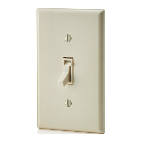
Single Pole (One location) or 3-Way (Multi-location)
Magnetic Low-Voltage Dimmer
INSTALLATION INSTRUCTIONS
MAXIMUM BULB WATTAGE AT 75% EFFICIENCY
Rating
1000VA
INSTALLING YOUR DIMMER
NOTE: Use check boxes
WARNING:
Step 1
POWER at circuit breaker or fuse and test that power is off
before wiring!
OFF
OFF
OFF
OFF
OFF
OFF
Removing existing switch:
Step 2
wallplate and switch mounting screws. Carefully pull switch
from wall box. DO NOT remove wires attached to the switch
at this time.
Identifying your wiring application (most
Step 3
common):
NOTE: If the wiring in the wall box does not resemble any of
these configurations, consult a qualified electrician.
1
More than
2 Devices
3
700VA
4
Single-Pole
1. Line (Hot)
2. Neutral
3. Ground
4. Load
Cat. No. TGM1Ø-1L (Lighted)
1000VA–120VAC, 60Hz
WARNINGS & CAUTIONS:
• When magnetic low-voltage circuits are operated at a dim level, with all lamps inoperative, excess
current may flow through the transformer. To avoid possible transformer failure due to overcurrent, use
a transformer that incorporates thermal protection or a fuse at the primary windings.
• Use only one (1) dimmer in a 3- or 4-way circuit. The switch(es) will turn the light on at the brightness
level selected at the dimmer.
• Disconnect power at circuit breaker or fuse when servicing fixture.
• Use this device only with copper or copper clad wire. With aluminum wire use only devices marked
CO/ALR or CU/AL.
• Recommended to use with non-metallic wallplates.
Two
More than
Single
Gang
2 Gang
750W
600W
525W
√
when Steps are completed.
To avoid fire, shock, or death; TURN OFF
ON
OFF
ON
ON
OFF
ON
ON
OFF
ON
ON
OFF
ON
ON
OFF
ON
ON
OFF
ON
Remove existing
2
1
2
3
4
5
3-Way
1. Line or Load (See important
instruction below)
2. Neutral
3. Ground
4. First Traveler – note color
5. Second Traveler – note color
Step 3 cont'd
IMPORTANT: For 3-Way applications, note that one of the screw
terminals from the old switch being removed will usually be a different
color (Black) or labeled Common. Tag that wire with electrical tape and
identify as the common (Line or Load) in both the dimmer wall box and
3-way wall box.
Preparing and connecting wires:
Step 4
• Make sure that the ends of the wires from the wall box are
straight (cut if necessary) .
• Remove 5/8" (1.6 cm) of insulation from each wire in the wall box
(shown).
• For Single-Pole Application, go to Step 5a.
• For 3-Way Application, go to Step 5b.
Cut
(if necessary)
(measure bare wire here)
Single-Pole Wiring Application:
Step 5a
This wire is used in 3-way installations only.
For single pole installations, do not remove this
insulating label.
Red
Neutral
1
2
Black
Green
3
Ground
Insert wires
4
Red
straight then twist
clockwise
5/8"
(1.6 cm)
Strip Gage
Electrical
Tape
Advertisement

Related Manuals for Leviton Toggle Touch TGM10-1L


Summary of Contents for Leviton Toggle Touch TGM10-1L
- Page 1 • Use with magnetic low-voltage transformers, incandescent, or 120V halogen fixtures only. Use a Leviton electronic low-voltage dimmer to control electronic (solid state) low-voltage transformers. • Total minimum wattage must exceed 40VA.
- Page 2 Leviton is not liable for incidental, indirect, special, or consequential damages, including without...