Table of Contents
Advertisement
Quick Links
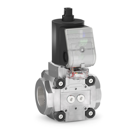
Magnetic relief valve VAn
Contents
1 Safety . . . . . . . . . . . . . . . . . . . . . . . . . . . . . . . . 1
2 Checking the usage . . . . . . . . . . . . . . . . . . . . . 2
3 Installation . . . . . . . . . . . . . . . . . . . . . . . . . . . . 2
4 Wiring . . . . . . . . . . . . . . . . . . . . . . . . . . . . . . . . 2
5 Tightness test. . . . . . . . . . . . . . . . . . . . . . . . . . 4
6 Replacing the actuator . . . . . . . . . . . . . . . . . . . 4
7 Maintenance. . . . . . . . . . . . . . . . . . . . . . . . . . . 5
8 Accessories . . . . . . . . . . . . . . . . . . . . . . . . . . . 5
9 Technical data . . . . . . . . . . . . . . . . . . . . . . . . . 6
10 Designed lifetime . . . . . . . . . . . . . . . . . . . . . . 7
11 Certification . . . . . . . . . . . . . . . . . . . . . . . . . . 7
12 Logistics . . . . . . . . . . . . . . . . . . . . . . . . . . . . . 8
13 Disposal . . . . . . . . . . . . . . . . . . . . . . . . . . . . . 8
oPeRAtInG InstRUCtIons
· Edition 05.22 · EN · 03250824
1 sAFetY
1.1 Please read and keep in a safe place
Please read through these instructions care-
fully before installing or operating. Following the installa-
tion, pass the instructions on to the operator. This unit
must be installed and commissioned in accordance
with the regulations and standards in force. These
instructions can also be found at www.docuthek.com.
1.2 explanation of symbols
1 , 2 , 3 , a , b , c = Action
➔ = Instruction
1.3 Liability
We will not be held liable for damage resulting from
non-observance of the instructions and non-com-
pliant use.
1.4 safety instructions
Information that is relevant for safety is indicated in the
instructions as follows:
DAnGeR
Indicates potentially fatal situations.
WARnInG
Indicates possible danger to life and limb.
CAUtIon
Indicates possible material damage.
All interventions may only be carried out by qualified
gas technicians. Electrical interventions may only be
carried out by qualified electricians.
1.5 Conversion, spare parts
All technical changes are prohibited. Only use OEM
spare parts.
Advertisement
Table of Contents

Related Manuals for Honeywell Krom Schroeder VAN Series


Summary of Contents for Honeywell Krom Schroeder VAN Series
-
Page 1: Table Of Contents
Magnetic relief valve VAn oPeRAtInG InstRUCtIons · Edition 05.22 · EN · 03250824 1 sAFetY 1.1 Please read and keep in a safe place Please read through these instructions care- fully before installing or operating. Following the installa- tion, pass the instructions on to the operator. This unit must be installed and commissioned in accordance with the regulations and standards in force. -
Page 2: Checking The Usage
2 CHeCKInG tHe UsAGe 3 InstALLAtIon Magnetic relief valve, open when de-energized, for the CAUtIon monitoring of gas valves for tightness used in conjunc- Incorrect installation tion with a visual discharge unit. For purging excess Please observe the following to ensure that the or leakage gas. - Page 3 1 Disconnect the system from the electrical power supply. 2 Shut off the gas supply. ➔ Wiring to EN 60204-1. ➔ Push through and remove the knock-out in the connection box before removing the cover. If the Closed position indicator M20 cable gland or plug is already fitted, it is not ➔...
-
Page 4: Tightness Test
5 tIGHtness test 1 Close the gas solenoid valve. 2 To be able to check the tightness, shut off the downstream pipeline close to the valve. 6 Open the solenoid valve. ➔ Depending on the construction stage of the unit, there are two different methods for replacing the actuator: If the unit concerned has no O-ring in this place (arrow), replace the actuator as described here. -
Page 5: Maintenance
8 ACCessoRIes 8.1 Pressure switch for gas DG..VC The pressure switch for gas monitors the inlet pres- sure p and the outlet pressure p ➔ Monitoring the inlet pressure p : the pressure 10 Position new actuator. switch for gas is mounted on the inlet side. 11 Follow the reverse procedure when reassembling. -
Page 6: Technical Data
8.2 seal set VA 1–2 9.2 Mechanical data When retrofitting accessories or a second valVario Gas types: natural gas, LPG (gaseous), biogas control or when servicing, we recommend replacing (max. 0.1 %-by-vol. H S) or clean air; other types the seals. of gas on request. -
Page 7: Designed Lifetime
Switching frequency of closed position indicator: max. 11 CeRtIFICAtIon 5 x per minute. 11.1 Declaration of conformity switching switching cycles* current cos φ = 1 cos φ = 0.6 500,000 500,000 We, the manufacturer, hereby declare that the products 300,000 250,000 VAN with product ID No. CE-0063BU1564 comply with 200,000 100,000 the requirements of the listed Directives and Standards. -
Page 8: Logistics
FoR MoRe InFoRMAtIon The Honeywell Thermal Solutions family of products includes Honeywell Combustion Safety, Eclipse, Exothermics, Hauck, Kromschröder and Maxon. To learn more about our products, visit ThermalSolutions.honeywell.com or contact your Honeywell Sales Engineer.