Table of Contents
Advertisement
Available languages
Available languages
Quick Links
OwNERS MANUAl
MANUAl DEl USUARIO
NOTICE D'UTIlISATION
Model No.
Modelo No.
Modèle No.
45-02941 (40")
45-02951 (48")
Read Rules for
Safe Operation
and Instructions
PRECAUCION:
Lea cuidadosamente
los Procedimientos e
Instrucciones para la
Operación Segura de la
ATTENTION:
Lire et suivre attentivement
les instructions et
consignes de sécurité de
cette notice.
PRINTED IN USA
™
CAUTION:
Carefully
• Safety
• Assembly
• Operation
• Maintenance
• Parts
Máquina.
the fastest way to purchase parts www.speedepart.com
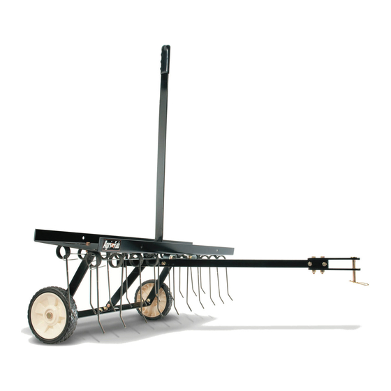
TINE DE-THATCHER
ADITAMENTO DE EXTRACCION DE PAJA
DECHAUMEUSE
• Seguridad
• Montaje
• Operación
• Mantenimiento
• Piezas de Repuesto
• Sécurité
• Assemblage
• Fonctionnement
• Entretien
• Pièces de Rechange
FORM NO. 48290 (Rev. 8/22/08)
Advertisement
Table of Contents

Related Manuals for Agri-Fab 45-02941


Summary of Contents for Agri-Fab 45-02941
- Page 1 ™ OwNERS MANUAl MANUAl DEl USUARIO NOTICE D’UTIlISATION Model No. Modelo No. Modèle No. 45-02941 (40") 45-02951 (48") CAUTION: Read Rules for Safe Operation and Instructions Carefully PRECAUCION: Lea cuidadosamente los Procedimientos e Instrucciones para la Operación Segura de la Máquina.
- Page 2 RUlES FOR SAFE OPERATIONS Remember, any power equipment can cause injury if operated improperly or if the user does not understand how to operate the equipment. lOOK FOR THIS SYMBOl TO POINT OUT IMPORTANT SAFETY PRECAUTIONS. IT MEANS -- ATTENTION! BECOME AlERT! YOUR SAFETY IS INVOlVED. Exercise caution at all times when using power equipment. 1. Read this owners manual carefully for operating and service instructions before attempting to assemble or operate this equipment. Be thoroughly familiar with the proper use of this equipment. 2. Read the vehicle owners manual and vehicle safety rules, and know how to operate the vehicle before using this equipment.
-
Page 3: Hardware Pack
HARDwARE PACK Qty. Description 40" 48" Shoulder Bolt Hex Bolt, 5/16" x 2" Lg. Hex Bolt, 5/16" x 1-1/4" Lg. Hex Bolt, 5/16" x 1" Lg. Carriage Bolt, 5/16" x 1" Hitch Pin, 3/8" ENGlISH SHOwN FUll SIZE NOT SHOwN FUll SIZE Qty. 40" Description 48" Hair Cotter Pin, 1/8" Nylock Nut, 3/8" Nylock Nut, 5/16" Angle Bracket Grip... -
Page 4: Tools Required For Assembly
ASSEMBlY INSTRUCTIONS TOOlS REQUIRED FOR ASSEMBlY (2) 1/2" wrenches (1) 9/16" wrench (1) 3/4" wrench or adjustable wrench (1) Pliers (1) Phillips screw driver or a round punch Before assembling the de-thatcher, lay out all of the parts and hardware as shown on the previous pages. The 40" dethatcher is shown in the drawings. T he assembly procedure is the same for the 48" dethatcher. 1. Assemble the lift plate to the top of the tine shield using four 5/16" x 1" hex bolts and 5/16" nylock nuts as shown in figure 1. Tighten. LIFT PLATE FIGURE 1 2. Turn the tine shield upside down. See figure 2. - Page 5 11. Assemble the axle bracket on the outside of the angle brackets using two 5/16" x 1" hex bolts and 5/16" nylock nuts. The ends of the axle bracket must point as shown in figure 5. Tighten and then loosen the bolts and nuts slightly. 5/16" x 1" HEX BOLT 5/16" NYLOCK NUT FIGURE 5 12. Assemble the wheels to the axle bracket using two shoulder bolts and two 3/8" nylock nuts. Tighten. See figure 6. SHOULDER BOLT 3/8" NYLOCK NUT FIGURE 6 13. Starting with the front row of tabs, slide a spring tine under a set of tabs. Insert a screw driver or punch down into the tray and bend each tab until the end of the tab is bent down even with the surface of the tray. Repeat to attach all spring tines. See figure 7.
-
Page 6: Operation / Adjustment
OPERATION / ADJUSTMENT Regular removal of thatch is critical to maintenance of a healthy lawn. Thatch is a layer of stems, clippings, run- ners, roots and leaves that have not decayed. Excessive thatch prevents air, water and fertilizer from reaching the roots. The de-thatcher effectively dislodges excessive thatch from your lawn. Read these instructions to help avoid improper adjustment and operation. Proper adjustment of the tine shield and spring tines is important for effective performance. Refer to the following steps for the proper adjustment before operating the de-thatcher. -
Page 7: Instrucciones De Ensamble
REGlAS PARA OPERACIONES SEGURAS Recuerde, cualquier equipo motorizado puede causar lesiones si se opera incorrectamente o si el usuario no entiende cómo operar el equipo. OBSERVE ESTE SIMBOlO PARA INDI- CAR PRECAUCIONES IMPORTANTES DE SEGURIDAD. ¡SIGNIFICA — ATENCION! ¡ESTE AlERTA! ESTA INVOlUCRADA SU SEGURIDAD. Sea precavido en todo momento al usar equipo motorizado. 1. Lea cuidadosamente este manual del propietario para las instrucciones de operación y servicio antes de intentar ensamblar u operar este equipo. Esté completamente familiarizado con el uso apropiado de este equipo. 2. Lea el manual del propietario del vehículo y las reglas de seguridad del vehículo, y cómo operar el vehículo antes de operar este equipo. 3. Nunca permita que los niños operen el tractor o el aditamento de extracción de paja, y no permita que los adultos los operen sin las instrucciones apropiadas. 4. Este aditamento de extracción de paja tiene puntas aguzadas de horquilla. Maneje siempre con cuidado y use calzado resistente al operar el extractor de paja. 5. No permita que nadie viaje o se siente en el chasis del aditamento del extractor de paja o en el vehículo de remolque. -
Page 8: Mantenimiento
7. Ensamble juntos los extremos delanteros de los brazos de montaje del enganche usando dos pernos hexagonales de 5/16" x 1-1/4" y contratuercas hexagonales de 5/16". No ajuste todavía. Vea la figura 4. 8. Ensamble los soportes del enganche al tope y fondo de los brazos de montaje del enganche usando dos pernos hexagonales de 5/16" x 2" y contratuercas hexagonales de 5/16". No ajuste todavía. Vea la figura 4. 9. Ensamble la clavija de enganche de 3/8" a través de los soportes del enganche y asegure con una clavija de broche de cabello de 1/8". -
Page 9: Regles De Securite
Rappelez-vous que tout engin motorisé peut causer des blessures s’il n’est pas utilisé correctement ou si l’utilisateur ne sait pas comment faire fonctionner l’équipement. CE SYMBOlE INDIQUE lES PRéCAUTIONS IMPORTANTES DE SéCURITé à PRENDRE. Il SIGNIFIE : ATTENTION ! SOYEZ AlERTE ! Il S’AGIT DE VOTRE SéCURITé. -
Page 10: Entretien
7. Réunissez les parties avant des bras du b â ti de l’attelage à l’aide de deux boulons à 6 pans 5/16" x 1-1/4" et contre- écrous à 6 pans de 5/16". Ne serrez pas encore. Voyez la figure 4. 8. Montez les équerres de fixation de l’attelage sur le haut et le bas des bras du b â ti de l’attelage à l’aide de deux boulons à 6 pans 5/16" x 2" et contre-écrous à 6 pans de 5/16". Ne serrez pas encore. Voyez la figure 4. 9. Passez la cheville de fixation 3/8" de l’attelage par les équerres de fixation de l’attelage et attachez la à l’aide d’une clavette transversale de 1/8". Voyez la figure 4. 10. Serrez les boulons et écrous assemblées sous point 8. Serrez les boulons et écrous assemblées sous point 7. - Page 11 TINE DE-THATCHER REPAIR PARTS MODEl NO's. 45-02941 (40") & 45-02951 (48") REF. PART QTY. DESCRIPTION NO. NO. 40" 48" 1 23442 Hitch Arm Mount Bracket 2 23981 Hitch Bracket 43783 Spring Tine 4 47633 Spring Alignment Wire 47654 Spring Alignment Wire 5 43021 Wheel 6 24836 Tine Shield (40")
-
Page 12: Repair Parts
REPAIR PARTS Agri-Fab, Inc. 303 West Raymond Sullivan, IL. 61951 217-728-8388 www.agri-fab.com This document (or manual) is protected under the U.S. Copyright Laws and the copyright laws of foreign countries, pursuant to the Universal Copyright Convention and the Berne convention. No part of this document may be reproduced or transmitted in any form or by an means, electronic or mechanical, including photocopying or recording, or by any information storage or retrieval system, without the express written permission of Agri-Fab, Inc. Unauthorized uses and/or reproductions of this manual will subject such unauthorized user to civil and criminal penalties as provided by the United States Copyright Laws. © 2002 Agri-Fab, Inc.