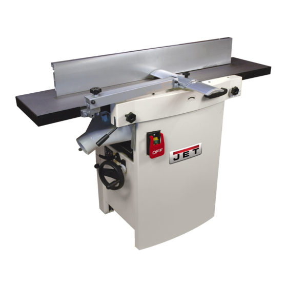
Jet JJP-12 Operating Instructions And Parts Manual
Jointer-planer
Hide thumbs
Also See for JJP-12:
- Brochure (4 pages) ,
- Brochure (2 pages) ,
- Operating instructions and parts manual (40 pages)
Table of Contents
Advertisement
Advertisement
Table of Contents
Troubleshooting

Related Manuals for Jet JJP-12


Summary of Contents for Jet JJP-12
- Page 1 This Manual is Bookmarked Operating Instructions and Parts Manual Model JJP-12 Jointer-Planer WMH TOOL GROUP, Inc. 2420 Vantage Drive Elgin, Illinois 60124 Part No. M-708475 Ph.: 800-274-6848 Revision A 10/07 www.wmhtoolgroup.com Copyright © 2007 WMH Tool Group, Inc.
-
Page 2: Warranty And Service
WMH Tool Group is consistently adding new products to the line. For complete, up-to-date product information, check with your local WMH Tool Group distributor, or visit jettools.com. WARRANTY JET products carry a limited warranty which varies in duration based upon the product (MW stands for Metalworking, WW stands for Woodworking). WHAT IS COVERED? This warranty covers any defects in workmanship or materials subject to the exceptions stated below. -
Page 3: Table Of Contents
Table of Contents Warranty and Service... 2 Table of Contents... 3 Warnings ... 4 Specifications ... 7 Features and Terminology ... 8 Receiving... 8 Unpacking ... 8 Electrical Connection ... 8 Operating Controls ... 9 Jointer to Planer Setup ... 9 Planer to Jointer Setup ... -
Page 4: Warnings
Warnings 1. Read and understand the entire owner's manual before attempting assembly or operation. 2. Read and understand the warnings posted on the machine and in this manual. Failure to comply with all of these warnings may cause serious injury. 3. - Page 5 22. Give your work undivided attention. Looking around, carrying on a conversation and “horse-play” are careless acts that can result in serious injury. 23. Maintain a balanced stance at all times so that you do not fall or lean against the spindle or other moving parts.
- Page 6 38. Move the hands in an alternate motion from back to front as the work continues through the cut. Never pass the hands directly over the cutter knife. As one hand approaches the knives remove it from the stock in an arc motion and place it back on the stock in a position beyond the cutter knife (Fig.
-
Page 7: Specifications
Specifications Model number ...JJP-12 Stock number ... 708475 Cutterhead speed...5500rpm Cutterhead diameter ...2-3/4" Number of knives ... 3 Cutter knife length ...12" Cutter knife thickness...1/8" Dust port diameter... 4” Jointer table...55"x12” Max stock removal ... 1/8” Fence ...43"x6” Fence tilt... 90°- 45° R Fence positive stop ...90°, 45°R... -
Page 8: Features And Terminology
The Model JJP-12 Jointer-Planer is rated at 230V. This machine is not supplied with a plug. Use a plug and outlet rated at least 20amps. -
Page 9: Operating Controls
Operating Controls Disconnect power source before making any adjustments. Failure to comply may cause serious injury. Cutterhead dangerously sharp. Use extreme caution when working around them. Failure to comply may cause serious injury. Jointer to Planer Setup To change the machine configuration jointer to planer (refer to Figure 2): 1. -
Page 10: Power
Power Once a properly rated plug is connected, plug power cord into outlet. Press the green on button (A, Fig. 4) to start. Press the red off button (B, Fig. 4) to stop. Planer Controls and Adjustments Referring to Figure 5: Power Feed Placing the planer power feed handle (D) in the up position turns the planer power feed on (see... - Page 11 handle for a deeper cut. 3. Tighten the lock knob (D). The infeed table lifting handle in the fully lowered position results in a depth of cut of 5/32". Note: A depth of cut of 1/16" or less is recom- mended.
-
Page 12: Adjustments
Adjustments Table and Knife Adjustments For accurate jointing, at least three things must be true: 1. Infeed and outfeed tables must be coplanar. 2. Knives or knife inserts must be set in the cutterhead so that the highest point of their arc is level with the outfeed table. - Page 13 Performing the Coplanar Alignment If alignment is required as determined in the previous section, proceed as follows: Disconnect power source before making any adjustments. Failure to comply may cause serious injury. Disconnect power from machine. Unlock both cabinet lock handles (A Raise the table (D) fully upright.
-
Page 14: Setting Cutterhead Knives
Setting Cutterhead Knives Important: Before performing any adjustments in this section, the infeed and outfeed tables must be coplanar (see Coplanar Alignment on page 12). Cutterhead dangerously sharp! Use extreme caution when inspecting, removing, sharpening or replacing knives into the cutterhead. Failure to comply may cause serious injury! 1. -
Page 15: Replacing Cutter Knives
Replacing Cutter Knives Disconnect power source before making any adjustments. Failure to comply may cause serious injury. 1. Disconnect machine from the power source. 2. Remove the cutterhead guard (B, Fig. 6). Cutterhead dangerously sharp. Use extreme caution when inspecting, removing, sharpening, or replacing knives into the cutterhead. -
Page 16: Belt Replacement
Belt Replacement Disconnect power source before making any adjustments. Failure to comply may cause serious injury. Preparation To replace the cutterhead drive belt and/or the planer feed-roller belt, the jointer fence assembly and two back panels must first be removed as described below. -
Page 17: Planer Table Adjustment
Planer Table Adjustment Disconnect power source before making any adjustments. Failure to comply may cause serious injury. Checking Planer Table Parallel to Cutterhead The planer table is set parallel to the cutterhead at the factory and no further adjustment should be needed. -
Page 18: Basic Operations
Basic Operations Dust Collection Before initial operation, the machine must be connected to a dust collector. Initial Startup After assembly adjustments complete the planer is ready to be tested. Turn on the power supply at the main panel. Press the Start button. Keep your finger on the Stop button in case of a problem. -
Page 19: Infeed Table
This may result in chipped and splintered edges. Feed with the grain to obtain a smooth surface, as shown in Figure 19. Figure 18 Figure 19 Jointing Jointing (or edging) is the process of creating a finished, flat edge surface that is suitable for joinery or finishing (Figure 20). -
Page 20: Planer Operations
Stand on the side that the handle is attached. Boards additional material stands. These can be purchased precision from JET – Stock # 709207. See Optional Accessories on page 22. Do not plane a board that is longer than 24”... - Page 21 Planing: 1. Position the workpiece with the face to be planed on top. 2. Turn the planer on. 3. Turn the power feed on. 4. Rest the board end on the infeed roller plate and direct the board into the planer. 5.
-
Page 22: Maintenance
Maintenance Blade Care Blades are extremely sharp! Use caution when cleaning or changing. Failure to comply may cause serious injury! The condition of the blades will affect the precision of the cut. Observe the quality of the cut that the planer produces to check the condition of the blades. -
Page 23: Troubleshooting
Troubleshooting Performance Troubleshooting – Jointer Trouble Probable Cause Finished stock is concave on back Knife is higher than outfeed table. end. Finished stock is Outfeed table is higher than knife. concave on front end. Chip out. Cutting against the grain. Dull knives. -
Page 24: Performance Troubleshooting - Planer
Performance Troubleshooting – Planer Trouble Probable Cause Snipe Table rollers not set properly. Inadequate support of long boards. Note: Snipe can be minimized but not Uneven feed roller pressure front to eliminated back. Dull knives. Lumber not butted properly. Fuzzy Grain Planing wood with high moisture content. -
Page 25: Mechanical Troubleshooting - Planer/Jointer
Mechanical Troubleshooting – Planer/Jointer Trouble Probable Cause Chain Inadequate jumping. tension. Sprockets misaligned. Sprockets worn. Machine will No incoming not start/ power. restart or repeatedly Overload trips circuit automatic reset breaker or has not reset blows fuses. Planer frequently trips. Building circuit breaker trips or fuse blows. -
Page 26: Parts List
Parts List Index No. Part No. 1 ...TS-1541031 ...Lock Nut ... M8 ... 4 2 ...JJP12-002...Washer..4 3 ...JJP12-003...Outfeed Table Bracket Shaft..1 4 ...JJP12-004...Outfeed Table Bracket, Right..1 5 ...TS-1504121 ...Socket Head Cap Screw... M8x60 ... 4 6 ...JJP12-006...Eccentric Shaft... - Page 27 Index No. Part No. 81 ...JJP12-081...Anti-Kickback Finger ..38 82 ...JJP12-082...Infeed Roller..1 83 ...JJP12-083...Anti-Kickback Shaft..1 84 ...JJP12-084...Cutterhead Cover..1 85 ...JJP12-085...Cutterhead Bracket, Right..1 86 ...TS-1550041 ...Flat Washer... M6 ... 4 87 ...TS-1503031 ...Socket Head Cap screw ... M6x12 ... 4 88 ...JJP12-088...Cutterhead Bracket Cover ...
- Page 28 Index No. Part No. 166 ...JJP12-166...Infeed Table Lock Handle ..1 167 ...JJP12-167...Infeed Scale, Inch ..1 168 ...JJP12-168...Thickness Scale, Inch ..1 169 ...JJP12-169...Washer... H8 ... 2 170 ...JJP12-170...Retaining Ring ..1 171 ...JJP12-011...Washer... H12 ... 1 172 ...TS-1504041 ...Socket Head Cap Screw...
- Page 29 Index No. Part No. 303 ...JJP12-303...Nut..2 304 ...JJP12-304...Locking Bar ..1 305 ...JJP12-305...Locking Shoe ..1 306 ...JJP12-306...Crank Handle ..1 307 ...JJP12-307...Hand Wheel ..1 308 ...TS-1503051 ...Socket Head Cap Screw... M6x20 ... 1 312 ...JJP12-154...Retaining Ring ...
-
Page 30: Assembly Drawings
Assembly Drawings Infeed Table Assembly... -
Page 31: Outfeed Table Assembly
Outfeed Table Assembly... -
Page 32: Cutterblock Assembly
Cutterblock Assembly... -
Page 33: Base Assembly
Base Assembly... -
Page 34: Motor Assembly
Motor Assembly... -
Page 35: Planer Table Assembly
Planer Table Assembly... -
Page 36: Fence Assembly
Fence Assembly... -
Page 37: Electrical Connection
Electrical Connection Accessories Stock No Description 708821 ...Replacement Knives for JJP-12 Jointer-planer (set of 3) 709207 ...13" Roller Stand... - Page 38 Notes...
- Page 39 Notes...
-
Page 40: Ordering Replacement Parts
Ordering Replacement Parts To order parts or reach our service department, call 1-800-274-6848 between 7:30am and 5:30pm (CST), Monday through Friday. Having the Model Number and Serial Number of your machine available when you call will allow us to serve you quickly and accurately. WMH Tool Group, Inc.