Icom IC-91A Instruction Manual
Vhf/uhf fm transceiver
Hide thumbs
Also See for IC-91A:
- Instruction manual (134 pages) ,
- Service manual (50 pages) ,
- Instruction manual (9 pages)
Table of Contents
Advertisement
Quick Links
Download this manual
See also:
Service Manual
INSTRUCTION MANUAL
VHF/UHF FM TRANSCEIVER
i91A
VHF/UHF DIGITAL TRANSCEIVER
i91AD
This device complies with Part 15 of the FCC Rules. Operation is sub-
ject to the following two conditions: (1) this device may not cause
harmful interference, and (2) this device must accept any interference
received, including interference that may cause undesired operation.
WARNING: MODIFICATION OF THIS DEVICE TO RECEIVE CEL-
LULAR RADIO TELEPHONE SERVICE SIGNALS IS PROHIBITED
UNDER FCC RULES AND FEDERAL LAW.
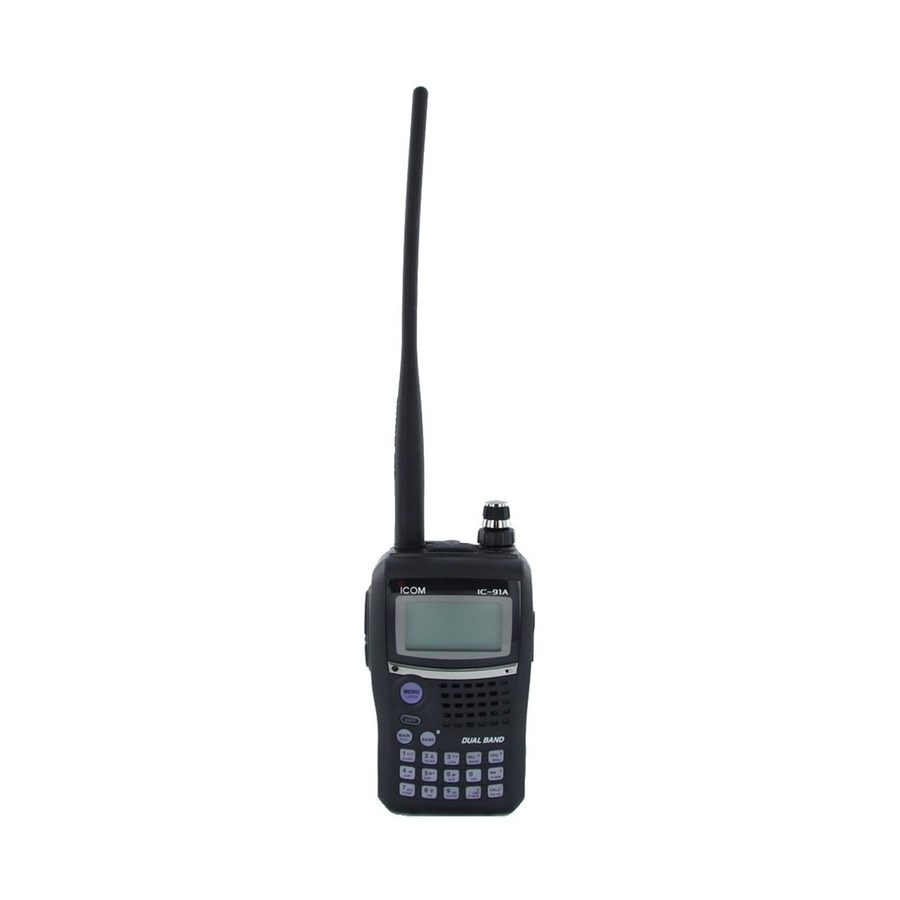
Y The above photo
shows IC-91AD.
Advertisement
Table of Contents

Related Manuals for Icom IC-91A


Summary of Contents for Icom IC-91A
- Page 1 INSTRUCTION MANUAL VHF/UHF FM TRANSCEIVER i91A VHF/UHF DIGITAL TRANSCEIVER i91AD This device complies with Part 15 of the FCC Rules. Operation is sub- ject to the following two conditions: (1) this device may not cause harmful interference, and (2) this device must accept any interference received, including interference that may cause undesired operation.
-
Page 2: Explicit Definitions
With proper care, this product should provide you with years of trouble-free operation. We want to take a couple of mo- ments of your time to thank you for making your IC-91A/91AD your radio of choice, and hope you agree with Icom’s philos- ophy of “technology first.”... -
Page 3: Precautions
For U.S.A. only CAUTION!: expressly approved by Icom Inc., could void your authority to operate this device under FCC regulations. The transceiver will become hot when op- Changes or modifications to this device, not... -
Page 4: Table Of Contents
I Duplex operation ……………………………………………… 31 I Auto repeater function I 1750 Hz tone ………………………………………………… 33 DV MODE OPERATION (Optional UT-121 is required for IC-91A) ………………… 34–63 I Digital mode operation ……………………………………… 34 I Call sign programming ……………………………………… 34 ……………………………… 13 I Digital voice mode operation …………………………………... - Page 5 I EMR communication ………………………………………… 56 I Low-speed data communication …………………………… 56 I GPS operation ………………………………………………… 58 I Other functions for DV mode operation …………………… 62 MEMORY/CALL CHANNELS …………………………… 64–73 I General description ………………………………………… 64 I Selecting a memory channel ………………………………… 64 I Selecting a call channel ………………………………………...
-
Page 6: Supplied Accessories
I Auto power ON ……………………………………………… 116 I Time-out timer ……………………………………………… 116 I PTT lock ……………………………………………………… 116 I Cloning function …………………………………………… 117 I [MIC/SP] jacks ……………………………………………… 117 I Resetting …………………………………………………… 118 13 TROUBLESHOOTING ………………………………………… 119 14 SPECIFICATIONS ……………………………………… 120–121 15 OPTIONS ………………………………………………… 122–124 I Optional UT-121 installation I Optional HM-75A REMOTE CONTROL MICROPHONE... -
Page 7: Accessory Attachment
I Antenna Insert the supplied antenna into the antenna connector and screw down Jack cover the antenna as shown at left. NEVER carry the transceiver by hold- ing the antenna. KEEP the jack cover attached when jack is not in use to protect the con- nector from dust and moisture. -
Page 8: Panel Description
PANEL DESCRIPTION I Front, top and side panels q ANTENNA CONNECTOR (p. 1) Connects the supplied antenna. • An optional AD-92SMA adapter (p. 122) is available for connect- ing an antenna with a BNC connector. w TX/RX INDICATOR [TX/RX] (p. 24) Lights green while receiving a signal or when the squelch is open;... - Page 9 o CALL/RX➝CS KEY [CALL]/[RX➝CS](CALL) ➥ Push to select the call channel/TV channel/weather channel. (p. 16) ➥ During DV mode operation, push and hold for 1 sec. to set the received call signs (station and repeaters) for operation. (p. 47) ➥ Enters or sends the DTMF code “C.” (pgs. 103, 104) !0 M EMORY/SELECT MEMORY WRITE KEY [MR]/[S.MW](MR) ➥...
- Page 10 PANEL DESCRIPTION D D KEYPAD Pushed momentarily • Inputs digit ‘1’ for frequency input, memory channel selection, etc. • While pushing [PTT], this key sends the DTMF code “1.” • Inputs digit ‘2’ for frequency input, memory channel selection, etc. •...
- Page 11 Pushed momentarily • Inputs digit ‘7’ for frequency input, memory channel selection, etc. • While pushing [PTT], this key sends the DTMF code “7.” • Inputs digit ‘8’ for frequency input, memory channel selection, etc. • While pushing [PTT], this key sends the DTMF code “8.” •...
-
Page 12: I Function Display
PANEL DESCRIPTION I Function display • Single band indication 439 706 • Dualwatch indication q BATTERY INDICATOR (pgs. 10, 12) ➥ “ tery pack is attached. ➥ “ ➥ The indicators show “ quence while charging the attached battery pack. w DUPLEX INDICATORS (p. - Page 13 ➥ “S” appears with the “DSQL” or “CSQL” indicator while the pocket beep function (with digital call sign or dig- is in use. (p. 111) ital code squelch) t KEY LOCK INDICATOR (pgs. 25, 113) Appears when the key lock function is activated. y AUTO POWER OFF INDICATOR (p.
-
Page 14: Battery Charging
Misuse can also cause damage to the battery or degra- dation of battery performance. • R DANGER! Use and charge only specified Icom battery packs with Icom radios. Only Icom battery packs are tested and approved for use with Icom radios. Using third-party or counterfeit battery packs may cause smoke, fire, or cause... - Page 15 • CAUTION! DO NOT charge the battery outside of the spec- ified temperature range: 0˚C to +35˚C (+32˚F to +95˚F). Icom recommends charging the battery at +20˚C (+68˚F). The battery may heat up or rupture if charged out of the specified temperature range.
-
Page 16: I Regular Charging
BATTERY CHARGING I Regular charging Prior to using the transceiver for the first time, the battery pack must be fully charged for optimum life and operation. D D Battery indicators The indicators show “ ,” “ while charging, and both indicators disappear when com- pletely charged. -
Page 17: I Rapid Charging
I Rapid charging The optional BC-139 provides rapid charging of the battery pack. • Charging period: 2.5 hours (with BP-217) D D Charging note • Be sure to turn the transceiver power OFF. Detach the battery pack from the transceiver then charge the battery pack by itself, or charge the battery with regular charging when the transceiver power cannot be turned OFF. -
Page 18: I Optional Battery Case
BATTERY CHARGING I Optional battery case ➥ Install 2 R6 (AA) size alka- line batteries into the op- tional BP-216 BATTERY CASE • Be sure to observe the cor- rect polarity. A built-in step-up convertor in the BP-216 increases the voltage to 5 V DC. -
Page 19: I External Dc Power Operation
I External DC power operation An optional cigarette lighter cable (CP-12L or CP-19R; for 12 V or external DC power cable cigarette lighter socket) can be used for external power operation. D D Operating note • Power supply range is between 10.0–16.0 V DC. NEVER CONNECT OVER 16 V DC directly into the [DC IN] jack of the transceiver. -
Page 20: Frequency And Channel Setting
FREQUENCY AND CHANNEL SETTING I Main band selection The IC-91A/91AD has two independent operating bands; A band and B band (VFO A) (VFO B) 0.495 MHz to 999.990 MHz*, and B band 118 MHz to 174 MHz and 350 MHz to 470 MHz. -
Page 21: I Mode Selection
I Mode selection D D VFO mode VFO mode is used to set the desired frequency. ➥ Push [VFO] to select VFO mode. • VFO mode indication 146 010 What is VFO? VFO is an abbreviation of Variable Frequency Oscillator. Fre- quencies for both transmitting and receiving are generated and controlled by the VFO. -
Page 22: I Operating Band Selection
FREQUENCY AND CHANNEL SETTING D D Call/TV*/Weather † channels Call channels are used for quick recall of most-often used fre- quencies. *Appears only when TV channels are programmed via the optional RS-91. Also available for A band operation only. † Available for the USA version only. - Page 23 • Available frequency bands • A band 001 620 005 000 AM broadcast band HF band 850 000 800 MHz band 440 000 400 MHz band • B band 118 000 146 010 VHF air band 144 MHz band FREQUENCY AND CHANNEL SETTING 051 000 50 MHz band 146 010...
-
Page 24: I Setting A Tuning Step
FREQUENCY AND CHANNEL SETTING I Setting a tuning step The tuning step can be selected for each frequency band. The following tuning steps are available for the IC-91A/91AD. • 5.0 kHz* • 6.25 kHz* • 8.33 kHz • 12.5 kHz • 15.0 kHz • 20.0 kHz • 25.0 kHz • 30.0 kHz •... - Page 25 D D Using the keypad The frequency can be directly set via numeric keys. • If a frequency outside the frequency range is en- tered, the previously displayed frequency is auto- matically recalled after editing last digit. qPush [VFO] to select VFO mode, if neces- sary.
-
Page 26: Basic Operation
BASIC OPERATION I Receiving Make sure charged battery pack (BP-217) or brand new al- kaline batteries (BP-216) are installed (pgs. 1, 12). q Push and hold [PWR] for 1 sec. to turn power ON. wRotate [VOL] to set the desired audio level. •... -
Page 27: I Setting Squelch Level
I Setting squelch level The squelch circuit mutes the received audio signal depend- ing on the signal strength. The receiver has 9 squelch levels, a continuously open setting and an automatic squelch setting. ➥ While pushing and holding [SQL], rotate [DIAL] to select the squelch level. -
Page 28: I Monitor Function
BASIC OPERATION I Monitor function This function is used to listen to weak signals without disturb- ing the squelch setting or to open the squelch manually even when mute functions such as the tone squelch are in use. ➥ Push and hold [SQL] to monitor the operating frequency. •... -
Page 29: I Band Scope
I Band scope The band scope function allows you to visually check a spec- ified frequency range around the center frequency. About the sweep steps: The specified tuning step in each frequency band or programmed tuning step (in VFO mode) is used during sweep. -
Page 30: I Transmitting
BASIC OPERATION I Transmitting CAUTION: Transmitting without an antenna will damage the transceiver. NOTE: To prevent interference, listen on the channel be- fore transmitting by pushing and holding [SQL]. q Set the operating frequency. (pgs. 18, 19) • Transmission is available on the 144 MHz/440 MHz amateur bands only. -
Page 31: I Lock Function
(p. 90) 146 010 I Dualwatch operation Dualwatch operation monitors two frequencies simultane- ously. The IC-91A/91AD has two independent receiver cir- cuits as A band and B band operating mode are different depending on bands) D D Dualwatch operation ➥... - Page 32 BASIC OPERATION D D Main band selection ➥ Push [MAIN/DUAL] to select A band or B band as the main operating band alternately. 146 010 440 000 146 010 440 000 D D Setting audio volume The audio level for dualwatch operation can be adjusted both on A band and B band simultaneously (default).
- Page 33 D D Volume setting for dualwatch The volume setting for dualwatch can be set for both bands simultaneously or for each band separately in set mode. q Enter “VOLUME SELECT” in sounds set mode. (p. 102) ➪ ➪ MENU screen SOUNDS...
-
Page 34: I Tv Channel Operation
BASIC OPERATION I TV channel operation TV channel operation is available only when TV channels are programmed using the optional RS-91. for A band operation only. D TV channel receiving q Push [CALL] several times to select TV channels. • “TV” and channel number appear. w Rotate [DIAL] to select the desired channel. -
Page 35: Repeater And Duplex Operations
REPEATER AND DUPLEX OPERATIONS I Repeater operation When using a repeater, the transmit frequency is shifted from the receive frequency by the offset frequency. venient to program repeater information into memory chan- nels. (p. 66) Repeater 144.700 MHz 144.700 MHz 145.300 MHz 145.300 MHz Station A... - Page 36 REPEATER AND DUPLEX OPERATIONS D Checking the repeater input signal The transceiver can check whether the other station’s trans- mit signal can be received directly or not, by listening on the repeater input frequency. ➥ Push and hold [SQL] to check whether the other station’s transmit signal can be directly received or not.
-
Page 37: I Duplex Operation
I Duplex operation Although [DIAL] and [ï](5) are used for description in this section, [∫ ∫ ](2)/[√ √ ](8) and [≈ ≈ ](6) are available instead of [DIAL] and [ï](5). D Setting offset frequency q Enter “OFFSET FREQ” in DUP/TONE… set mode. (p. 97) ➪... -
Page 38: I Auto Repeater Function
REPEATER AND DUPLEX OPERATIONS I Auto repeater function The U.S.A. and Korean versions automatically use standard repeater settings (duplex ON/OFF, duplex direction, tone encoder when the operating frequency falls within or outside ON/OFF) of the general repeater output frequency range. The offset and repeater tone frequencies are not changed by the auto repeater function, reset these frequencies, if necessary. -
Page 39: I 1750 Hz Tone
I 1750 Hz tone Some European repeaters require a 1750 Hz tone burst to be accessed. For such European repeaters, perform the follow- ing. • This tone can be use as a ‘Call signal’ in countries out of Europe. q Push and hold [DTMF.M](.) for 1 sec. to select DTMF memory. -
Page 40: Dv Mode Operation (Optional Ut-121 Is Required For Ic-91A)
[∫ ∫ ](2)/[√ √ ](8) and [≈ ≈ ](6) are available instead of [DIAL] and [ï](5). I Digital mode operation The IC-91A*/91AD can be operated in digital voice mode and low-speed data operation for both transmit and receive. It can also be connected to a GPS receiver 232 output/NMEA format/4800 bps) data. - Page 41 Push [≈ ≈ ](6) several times to set the cursor beside “/” indi- cation. o Repeat steps t to y to program the desired 4-character note. DV MODE OPERATION (Optional UT-121 is required for IC-91A) !0 Push [ï](5) to store the programmed call sign with note † to se- and returns to MY CALL SIGN screen.
- Page 42 DV MODE OPERATION (Optional UT-121 is required for IC-91A) D D Station call sign programming Station call sign must be programmed for the specified sta- tion call as well as repeater operation in both digital voice and low-speed data communications.
- Page 43 However, you must manually over-write a programmed call sign in regular memory and call channels. (Temporary opera- tion without over-writing is possible.) [DIAL] ↔ [∫ ∫ ](2)/[√ √ ](8) [ï](5) ↔ [≈ ≈ ](6) † DV MODE OPERATION (Optional UT-121 is required for IC-91A) (p. 95)
-
Page 44: I Digital Voice Mode Operation
DV MODE OPERATION (Optional UT-121 is required for IC-91A) I Digital voice mode operation qSet the desired frequency in B band. • Select output power, if desired. (p. 24) w Select DV mode. (p. 21) e Set your own call sign for DV operation as follows. - Page 45 [MENU/LOCK] to return to frequency indication. m Perform the instruction steps t and y on page 38. DV MODE OPERATION (Optional UT-121 is required for IC-91A) D D When sending a CQ Continued instruction from step x on page 38.
-
Page 46: I About D-Star System
DV MODE OPERATION (Optional UT-121 is required for IC-91A) I About D-STAR system In the D-STAR system, repeater linking via a 10 GHz band backbone and internet network (gateway connection) capa- bilities are available. This system provides you to with much wider coverage range during digital voice mode operation. -
Page 47: I Digital Repeater Operation
• Push [≈ ≈ ](6) to move the cursor right; push [Ω Ω ](4) to move the cursor left. • 2nd digit blinks (1st digit stops blinking). DV MODE OPERATION (Optional UT-121 is required for IC-91A) u Repeat the steps t and y to enter the desired repeater call sign. - Page 48 DV MODE OPERATION (Optional UT-121 is required for IC-91A) D D Repeater operation in the same zone qSet the desired repeater’s frequency, offset and shift direc- tion in B band. (pgs. 18, 31) • Select DV mode in advance. (p. 21) w Set your own call sign.
- Page 49 D-STAR system. ❑ The setting when Station A is call- ing Station B : A2222B : A22222 : NOT USEQ : A2222A DV MODE OPERATION (Optional UT-121 is required for IC-91A) Zone Repeater 2 Area 3 : A22222 (Gateway) Station B...
- Page 50 DV MODE OPERATION (Optional UT-121 is required for IC-91A) D D Repeater operation into another zone qSet the desired repeater’s frequency, offset and shift direc- tion in B band. (pgs. 18, 31) • Select DV mode in advance. w Set your own call sign.
- Page 51 : B6666C ❑ The setting when Station A is call- ing Station C : B6666C : A22222 : A33333 G : A2222A DV MODE OPERATION (Optional UT-121 is required for IC-91A) Area 3 (Gateway) Repeater 2 : A22222 Internet Internet...
-
Page 52: I Received Call Sign
DV MODE OPERATION (Optional UT-121 is required for IC-91A) I Received call sign When a call is received in DV mode, the calling station and the repeater call signs being used can be stored into the re- ceived call record. The stored call signs are viewable in the following manner. - Page 53 • Error beeps sound when a call sign is received incorrectly, and no call sign is set in this case. wPush [PTT] to transmit; release to receive. DV MODE OPERATION (Optional UT-121 is required for IC-91A) Important! Setting call signs with the “One-touch reply using the call record”...
-
Page 54: I Copying The Call Sign
DV MODE OPERATION (Optional UT-121 is required for IC-91A) I Copying the call sign D D Copying the call sign memory contents This function is convenient when or modifying a part of the current call sign. NOTE: Make sure that the “EDIT RECORD” item in DV set mode is set to “AUTO”... - Page 55 [ï](5) to store the edited/modified call sign into the selected channel. [DIAL] ↔ [∫ ∫ ](2)/[√ √ ](8) [ï](5) ↔ [≈ ≈ ](6) † DV MODE OPERATION (Optional UT-121 is required for IC-91A) Call sign channel number bliks.
- Page 56 DV MODE OPERATION (Optional UT-121 is required for IC-91A) D D Copying the call record contents into call sign memory This is a way to copying the call record contents into call sign memory “RXRPT1” and “RXRPT2”) at the same time or individually.
-
Page 57: I Break-In Communication
After receiving the reply call, communicate normally. yTo cancel the break-in, push and hold [BK](9) for 1 sec. to turn OFF. DV MODE OPERATION (Optional UT-121 is required for IC-91A) • How to use the break-in? While operating with the call sign squelch... -
Page 58: I Message Operation
DV MODE OPERATION (Optional UT-121 is required for IC-91A) I Message operation D D TX message programming TX messages are available for up to 5 channels and each channel can be programmed with a message of up to 20 characters. Available characters are 0 to 9, A to Z , a to z , some symbols and space. - Page 59 OFF, or overwritten when another message is re- ceived. A transmitted message that includes lower case charac- ters from the IC-91A/91AD may not be decoded and dis- played correctly by the ID-800H, IC-V82/U82, etc. [DIAL] ↔ [∫ ∫ ](2)/[√ √ ](8) †...
-
Page 60: I Automatic Reply Function
DV MODE OPERATION (Optional UT-121 is required for IC-91A) D D RX message indication The received message can also be checked in DV set mode. q Select “RX MESSAGE” in message/position set mode. ➪ MENU screen MESSAGE/POSITION (Push [MENU/LOCK]) (Rotate [DIAL] •... - Page 61 Push [Ω Ω ](4) to return to DV VOICE MEMO screen. t Push [MENU/LOCK] to return to frequency indication. DV MODE OPERATION (Optional UT-121 is required for IC-91A) D D Play-back or erase the voice memory q Push [MENU/LOCK] to select menu mode indication.
-
Page 62: I Emr Communication
DV MODE OPERATION (Optional UT-121 is required for IC-91A) I EMR communication The EMR communication mode is available for digital mode operation. In the EMR communication mode, no call sign set- ting is necessary. When an EMR communication mode sig- nal is received, the audio (voice) will be heard at the specified... - Page 63 PC. Release [PTT] to receive. • Under computer control, see Transmission condition setting at right. DV MODE OPERATION (Optional UT-121 is required for IC-91A) D D Transmission condition setting q Enter “DV DATA TX” in DV set mode.
-
Page 64: I Gps Operation
DV MODE OPERATION (Optional UT-121 is required for IC-91A) I GPS operation During GPS mode operation, a GPS receiver can be connected to the [DATA] socket of put/NMEA format) the IC-91A/91AD to indicate the current position . The position data is transmitted with your voice sig- Longitude) nals at the same time. - Page 65 • Push [≈ ≈ ](6) to move the cursor right; push [Ω Ω ](4) to move the cursor left. • 2nd digit blinks (1st digit stops blinking). DV MODE OPERATION (Optional UT-121 is required for IC-91A) t Repeat the steps r and t to enter the desired message. • Up to 20-character messages can be set.
- Page 66 DV MODE OPERATION (Optional UT-121 is required for IC-91A) D D GPS message automatic transmission q Enter “GPS AUTO TX” in DV set mode. ➪ MENU screen DV SET MODE (Push [MENU/LOCK]) (Rotate [DIAL] • GPS AUTO RX screen is displayed.
- Page 67 MESSAGE/POSITION (or [Ω Ω ](4)) screen. e Push [MENU/LOCK] to return to frequency indication. [DIAL] ↔ [∫ ∫ ](2)/[√ √ ](8) [ï](5) ↔ [≈ ≈ ](6) † DV MODE OPERATION (Optional UT-121 is required for IC-91A) ➪ RX GPS †...
-
Page 68: I Other Functions For Dv Mode Operation
DV MODE OPERATION (Optional UT-121 is required for IC-91A) I Other functions for DV mode operation D D DV voice memory The IC-91A/91AD has a DV voice memory that records a total 30 second of received audio. (approx.) The DV voice memory is divided into 2 tracks, 15 seconds each in a track, as the default setting. - Page 69 Push [Ω Ω ](4) to return to DV VOICE MEMO screen. u Push [MENU/LOCK] to return to frequency indication. DV MODE OPERATION (Optional UT-121 is required for IC-91A) D D DV automatic detect The “DV” mode indicator blinks when a non-DV signal is re- ceived during DV mode operation.
-
Page 70: Memory/Call Channels
MEMORY/CALL CHANNELS I General description The IC-91A/91AD has 850 memory channels in A band, 450 memory channels in B band, and 2 call channels in each band. Memory channels in each bands including 50 scan edge memory channels (25 pairs) frequencies, respectively. -
Page 71: I Selecting A Call Channel
[DIAL] 146 010 Rotate [DIAL] to select the memory channel. D D Using the KEYPAD qPush [MR] to select memory mode. wPush the keypad to enter 3 digits to select the desired memory channel. • The blank channels are also selectable. •... -
Page 72: I Memory Channel Programming
MEMORY/CALL CHANNELS I Memory channel programming q Push [VFO] to select VFO mode. w Set the desired frequency: ➥ Select the desired band with [BAND]. ➥ Set the desired frequency with [DIAL]. ➥ Or set the desired frequency with keypad directly. In this case, the band and frequency settings with [BAND] and [DIAL] as above are not required. -
Page 73: I Memory Bank Setting
I Memory bank setting The IC-91A/91AD has a total of 26 banks (A to Z). Regular memory channels, 000 to 799 (A band)/000 to 399 (B band), are assigned to the desired bank for easy memory manage- ment. qPush and hold [S.MW](MR) for 1 sec. to enter select mem- ory write mode. -
Page 74: I Memory Bank Selection
MEMORY/CALL CHANNELS I Memory bank selection qPush [MR] several times to select memory bank mode. wWhile pushing and holding [BAND], rotate [DIAL] to select the desired bank (A to Z). • Only programmed banks are displayed. [DIAL] eRotate [DIAL] to select the bank channel. •... -
Page 75: I Programming Memory/Bank/Scan Name
I Programming memory/bank/scan name Each memory channel can be programmed with an alphanu- meric channel name for easy recognition and can be indi- cated independently by channel. Names can be a maximum of 8 characters. NOTE: Scan name indication can be turned ON or OFF in display set mode. -
Page 76: I Selecting Memory/Bank Name Indication
MEMORY/CALL CHANNELS [EXAMPLE]: Programming the bank name “AIR” into the scan edge channel 03A. Push to select memory mode. 145 870 µ Rotate [DIAL] to select scan edge channel 03A. 127 500 µ Push for 1 sec. Enter select memory write mode. -
Page 77: I Copying Memory/Call Contents
I Copying memory/call contents This function transfers a memory channel’s contents to VFO (or another memory/call channel). This is useful when search- ing for signals around a memory channel frequency and for recalling the offset frequency, subaudible tone frequency etc. D Memory/call➪VFO q Select the memory (call) channel to be copied. -
Page 78: I Memory Clearing
MEMORY/CALL CHANNELS I Memory clearing Contents of programmed memories can be cleared (blanked), if desired. qPush and hold [S.MW](MR) for 1 sec. to enter select mem- ory write mode. • 1 short and 1 long beeps sound. • “µ µ ”... -
Page 79: I Erasing/Transferring Bank Contents
I Erasing/transferring bank contents The bank contents of programmed memory channels can be cleared or reassigned to another memory bank. INFORMATION: Even if the memory bank contents are cleared, the memory channel contents still remain pro- grammed. qSelect the desired bank contents to be transferred or erased from the bank. -
Page 80: Scan Operation
SCAN OPERATION I Scan types Scanning searches for signals automatically and makes it easier to locate new stations for contact or listening purposes. FULL SCAN (p. 75) 999.990 Scan Jump PROGRAMMED SCAN (p. 75) Band Scan edges Band edge edge Scan Jump ALL/SELECTED BANK... -
Page 81: I Full/Band/Programmed Scan
I Full/band/programmed scan q Push [VFO] to select VFO mode • Select the desired frequency band with [BAND], if desired. w Set the squelch level. eWhile pushing and holding [SCAN](2), rotate [DIAL] to se- lect the desired scanning type. • “ALL” for full scan; “BAND” for band scan, “PROG-xx (or scan name if programmed)”... -
Page 82: I Scan Edges Programming
SCAN OPERATION I Scan edges programming Scan edges can be programmed in the same manner as memory channels. Scan edges are programmed into scan edges, 00A/00B to 24A/24B, in memory channels. q Push [VFO] to select VFO mode. w Set the desired frequency: ➥... -
Page 83: I Memory Scan
I Memory scan IMPORTANT!: To perform memory scan, 2 or more mem- ory channels MUST be programmed, otherwise the scan will not start. qPush [MR] to select memory mode. w Set the squelch level. eWhile pushing and holding [SCAN](2), rotate [DIAL] to se- lect the desired scanning type. -
Page 84: I Memory Bank Scan
SCAN OPERATION I Memory bank scan IMPORTANT!: To perform memory bank scan, 2 or more bank channels MUST be programmed, otherwise the scan will not start. qPush [S.MW](MR) several times to select memory bank mode. w Set the squelch level. eWhile pushing and holding [SCAN](2), rotate [DIAL] to se- lect the desired scanning type. -
Page 85: I Skip Channel/Frequency Setting
I Skip channel/frequency setting Memory channels can be set to be skipped for memory skip scan. In addition, memory channels can be set to be skipped for both memory skip scan and frequency skip scan. These are useful to speed up the scan rate. q Select a memory channel: ➥... - Page 86 SCAN OPERATION tPush and hold [S.MW](MR) for 1 sec. to store the skip con- dition into the memory. • “SKIP” or “P SKIP” indicator appears, according to the skip se- lection in the step r. • Skip channel setting 145 700 µ...
-
Page 87: I Scan Resume Condition
I Scan resume condition D D Scan pause timer The scan pauses when receiving signals according to the scan pause time. It can be set from 2 to 20 sec. or unlimited. q Enter “PAUSE” in scan set mode. (p. 96) ➪... -
Page 88: Priority Watch
PRIORITY WATCH I Priority watch types Priority watch checks for signals on the frequency every 5 sec. while operating on a VFO frequency or scanning. The transceiver has 3 priority watch types to suit your needs. The watch resumes according to the selected scan resume condition. -
Page 89: I Priority Watch Operation
I Priority watch operation Although [DIAL] and [ï](5) are used for description in this section, [∫ ∫ ](2)/[√ √ ](8) and [≈ ≈ ](6) are available instead of [DIAL] and [ï](5). D D Memory/call channel and memory scan watch q Select VFO mode; then, set an operating frequency. w Set the watching channel(s). - Page 90 PRIORITY WATCH D D VFO scan watch q Set the watching channel(s). For memory channel watch: Select the desired memory channel. For call channel watch: Select the desired call channel. For memory scan watch: Select memory mode, or the desired bank group; then, push and hold [SCAN](2) for 1 sec.
-
Page 91: Menu Screen Operation
I General MENU screen is used for programming infrequently changed values or conditions of functions. D D Entering MENU screen and operation e.g.) Set “AUTO power OFF” to 30 minutes. q Push [MENU/LOCK] to enter MENU screen. • MENU groups appear. -
Page 92: I Menu Screen Indication For B Band
MENU SCREEN OPERATION I MENU screen indication for B band* While B band is selected, MENU screen shows following in- dication. MENU screen indication for B band. *The optional UT-121 is required for IC-91A. I Menu list MENU REF. † —... - Page 93 95 p. 100 TX CALL SIGN* p. 100 RX MESSAGE* Available for B band of IC-91AD, or UT-121 is installed IC-91A only. Available for B band of IC-91AD, or if the UT-121 is installed in the REF. IC-91A. p. 97 D D SOUNDS set mode p.
-
Page 94: I Set Mode Items
MENU SCREEN OPERATION I Set mode items D D Auto power OFF The transceiver can be set to automatically turn OFF after a specified time period with a beep when no key operations are performed. 30 min., 60 min, 90 min, 120 min and OFF specified. - Page 95 D D Monitor key action The monitor key, [SQL] , can be set as a ‘sticky’ key. When set to the sticky condition, each push of [SQL] toggles the monitor function ON and OFF. • PUSH: Pushing and holding [SQL] to monitor the fre- quency.
- Page 96 MENU SCREEN OPERATION D D Microphone simple mode Microphone simple mode is used to change the function as- signments for keys on the optional HM-75A (pgs. 122, 124) SPEAKER MICROPHONE • SIMPLE • NORM-1 (default) • NORM-2 D D Weather alert function Turns weather alert function ON and OFF.
- Page 97 D D PTT lock Turns the PTT lock function ON and OFF. Transmission with [PTT] is inhibited when ON is selected to prevent accidental transmission, etc. D D Busy lockout Turns the busy lockout function ON and OFF. This function inhibits transmission while receiving a signal or when the squelch is open.
-
Page 98: I Dv Set Mode Items
MENU SCREEN OPERATION I DV set mode items The following items are selectable by the IC-91AD or optional UT-121 is installed into the IC-91A. D D Auto reply This function replies to an individual station call even you are away from the transceiver. - Page 99 D D Digital monitor Sets the desired monitoring mode during digital mode opera- tion from “Auto,” “Digital” and “Analog.” • AUTO : The transceiver sets monitoring mode to FM and DV according to the received signal. fault) • DIGITAL : Monitors in DV mode. •...
- Page 100 MENU SCREEN OPERATION D D GPS mode Sets GPS mode operation ON and OFF. When the position information is received from a connected GPS receiver and the GPS Auto TX Timer setting (p. 95) is set to a specific time, the transceiver automatically transmits with the current position and message at every setting inter- val.
- Page 101 D D GPS auto TX timer Selects the desired interval for automatic position transmis- sion function from 5, 10, 30 second, 1, 3, 5, 10 and 30 min- utes. D D DV auto detect When a signal other than DV mode is received during DV mode operation, the transceiver has capability of automatic FM mode selection.
-
Page 102: I Scan Set Mode Items
MENU SCREEN OPERATION I Scan set mode items D D Priority watch Activates priority watch or priority watch with alert • OFF : The priority watch is turned OFF. • ON : The transceiver checks the memory channel fre- quency every 5 sec. •... -
Page 103: I Dup/Tone Set Mode Items
D D Memory bank link function Sets the memory bank link function ON (default) link function provides continuous bank scan, scanning all con- tents in the selected banks during bank scan. • Bank link setting q Rotate [DIAL] † to select the bank that you want to change. w Push [ï](5) †... - Page 104 MENU SCREEN OPERATION D D TSQL frequency Selects tone frequency for tone squelch or pocket beep oper- ation from one of 50 available frequencies • Available subaudible tone frequencies 67.0 79.7 94.8 110.9 131.8 69.3 82.5 97.4 114.8 136.5 71.9 85.4 100.0 118.8...
-
Page 105: I Display Set Mode Items
D D DTCS polarity Sets DTCS polarity from “BOTH N” (TX/RX: normal) , “TR-RN” (TX: normal, RX: reverse) (TX: reverse, RX: normal) “BOTH R” (TX/RX: reverse) TX/RX: Normal polarity TX/RX: Reverse polarity D D DTMF speed Select the desired DTMF transmission speed from 100 msec, 200 msec, 300 msec, 500 msec. - Page 106 When a call is received, the calling station call sign can be in- dicated automatically. D D TX Call Sign Display Available for IC-91AD, or if the UT-121 is installed in the IC-91A. Selects call sign display function from YOUR, MY and OFF. (default: 8)
- Page 107 • OFF : Opening logo indication is skipped. MENU SCREEN OPERATION D D Opening call sign Available for IC-91AD, or if the UT-121 is installed in the IC-91A. The set your own call sign, programmed in my call sign, can be displayed at power ON.
-
Page 108: I Sounds Set Mode Items
(default: ON) D D Standby Beep (default: OFF) Available for IC-91AD, or if the UT-121 is installed in the IC-91A. Turns the beep emission capability ON and OFF when the com- municating station finishes transmitting or the receive signal dis- appears while in the digital mode operation. -
Page 109: Other Functions
I Programming a DTMF code DTMF codes are used for autopatching, accessing repeaters, controlling other equipment, etc. The transceiver has 10 DTMF memory channels (Ch01–Ch10) for storage of often- used DTMF codes of up to 16 digits. q Push and hold [DTMF.M](.) for 1 sec. to enter DTMF mem- ory. -
Page 110: I Transmitting A Dtmf Code
OTHER FUNCTIONS I Transmitting a DTMF code D Transmitting from DTMF memory The selected DTMF code is transmitted at each push of the [SQL] switch while transmitting. The transmitting speed at which DTMF memories send in- dividual DTMF characters can be set in “DTMF SPEED” menu. -
Page 111: I Clearing A Dtmf Memory
I Clearing a DTMF memory An unwanted DTMF memory can be cleared (erased). q Push and hold [DTMF.M](.) for 1 sec. to enter DTMF mem- ory mode. w Rotate [DIAL] † to select the desired DTMF memory chan- nel to be cleared. e Push and hold [CLR](1) for 1 sec. -
Page 112: I Setting Dtmf Transfer Speed
OTHER FUNCTIONS I Setting DTMF transfer speed The DTMF transfer speed can be selected. q Enter “DTMF SPEED” in DUP/TONE… set mode. ➪ MENU screen DUP/TONE... (Push [MENU/LOCK]) (Rotate [DIAL] w Rotate [DIAL] † to select DTMF transfer speed as below. 100: Transfer the DTMF data per about 100 msec. -
Page 113: Tone Squelch
D Setting subaudible tones for repeater or tone squelch q Enter “CTCSS TONE (or RPT TONE)” in DUP/TONE… set mode. (pgs. 97, 98) ➪ ➪ MENU screen DUP/TONE... † (Push [MENU/LOCK]) (Rotate [DIAL] , then push [ï](5) w Rotate [DIAL] †... -
Page 114: I Digital Code And Digital Call Sign Setting
• Input the call sign if the desired call sign is not stored in the transceiver. See p. 36 for detail. r Push [ï](5) [DIAL] ↔ [∫ ∫ ](2)/[√ √ ](8) † The optional UT-121 is required for the IC-91A ➪ ➪ CALL SIGN YOUR CALL SIGN... - Page 115 t Rotate [DIAL] † to select “MY CALL SIGN” in CALL SIGN † set mode, then push [ï](5) to enter “MY CALL SIGN” set- ting. ➪ ➪ MENU screen CALL SIGN † (Push [MENU/LOCK]) (Rotate [DIAL] , then push [ï](5) y Rotate [DIAL] †...
-
Page 116: I Tone/Dtcs Squelch
S-in- 145300 dicator shows signal strength. • To open the squelch manually, push and hold [SQL]. 145300 145300 145300 The optional UT-121 is required for the IC-91A 145300 145300 145300 145300 145300 145300... -
Page 117: I Pocket Beep Function
145300 145300 I Pocket beep function 145300 145300 q Set the desired operating frequency. w Set the desired CTCSS tone, DTCS code, Digital call sign or Digital code. 145300 145300 e Push and hold [TONE](7)/[DSQ](7) for 1 sec. several times to activate the pocket beep, DTCS beep, Digital call sign beep or Digital code beep. -
Page 118: I Tone Scan
OTHER FUNCTIONS I Tone scan The transceiver can detect the subaudible tone frequency and DTCS code in a received signal. By monitoring a signal that is being transmitted on a repeater input frequency, you can determine the tone frequency required to access the repeater. q Set the desired frequency or memory channel to be checked for a tone frequency or DTCS code. -
Page 119: I Beep Tones
I Beep tones You can select to have confirmation beeps sound at the push of a switch. The output level can be adjusted within 39 levels with “BEEP LEVEL” in sounds set mode. ➪ ➪ MENU screen SOUNDS † (Push [MENU/LOCK]) (Rotate [DIAL] , then push [ï](5) You can select silent operation by turning beep tones OFF with “KEY-TOUCH BEEP”... -
Page 120: I Weather Channel Operation
OTHER FUNCTIONS I Weather channel operation There are 10 weather channels for monitor- ing weather channels from the NOAA (Na- tional Oceanographic and Atmospheric Administration) broadcasts. D D Weather channel selection q Push [CALL] several times to select weather channel mode. -
Page 121: I Power Save
y When the alert is detected, a beep sounds and the follow- ing indication will be displayed. Shows above indications alternately. u Turn the weather alert function OFF in set mode. NOTE: While receiving a signal (on a frequency other than the weather alert ON frequency), the receiving signal or audio will be interrupted momentarily every 5 sec. -
Page 122: I Auto Power Off
OTHER FUNCTIONS I Auto power OFF The transceiver can be set to automatically turn OFF after a specified period with a beep when no switch is pushed. 120 min., 90 min., 60 min., 30 min. and OFF can be speci- fied. -
Page 123: I Cloning Function
I Cloning function The IC-91A/91AD has transceiver-to-transceiver data cloning capability. This function is useful when you want to copy all of the programmed contents from one IC-91A/91AD to an- other. • An optional OPC-474 CLONING CABLE q Turn the transceiver’s power OFF, then connect an op- tional OPC-474 between both [SP] jacks. -
Page 124: I Resetting
OTHER FUNCTIONS I Resetting The function display may occasionally display erroneous information (e.g. when first applying power). This may be caused externally by static electricity or by other factors. If this problem occurs, turn power OFF. After waiting a few seconds, turn power ON again. -
Page 125: Troubleshooting
If your transceiver seems to be malfunctioning, please check the following points before sending it to a service center. POSSIBLE CAUSE PROBLEM • The batteries are exhausted. No power comes ON. • The battery polarity is reversed. • Volume level is too low. No sound comes from the •... -
Page 126: Specifications
(–20°C to +60°C; –4°F to +140°F) † † (approx.) (dualwatch; FM/DV † † Available for the IC-91AD or when UT-121 is installed into the IC-91A. (dualwatch; FM/DV † ‡ Selectable depending on the operating frequency band. : SMA (50 Ω) : 58.4(W)×103(H)×34.2(D) mm;... - Page 127 (WFM) • Audio output power (at 7.4 V DC) • Ext. speaker connector † Available for the IC-91AD or when UT-121 is installed into the IC-91A. SPECIFICATIONS More than 50 dB † More than 45 dB More than 300 kHz/–3 dB Less than 700 kHz/–20 dB...
-
Page 128: Options
OPTIONS • UT-121 DIGITAL UNIT Provides DV mode operation for IC-91A. Already installed into the IC-91AD. • RS-91 REMOTE CONTROL SOFTWARE Allows you to operate the transceiver, as well as the easy memory management from the connected PC for Microsoft ®... -
Page 129: I Optional Ut-121 Installation
Push both edges of the UT-121 to install it into the trans- ceiver, then confirm to install it completely. y Screw 2 screws to assemble the unit cover. OPTIONS IC-91A only • Upper view UT-121 • Side view Unit installer guide... -
Page 130: I Optional Hm-75A
OPTIONS I Optional HM-75A The optional HM-75A allows you to remotely select operating frequencies, memory channels, etc. Remote control functions can be selected from 3 settings. These can be selected with “MIC SIMPLE MODE” in set mode. (p. 90) ➪ MENU screen... - Page 131 A-6502H-1EX Printed in Japan 1-1-32 Kamiminami, Hirano-ku, Osaka 547-0003, Japan 2006 Icom Inc. ©...