Advertisement
Quick Links
531344-1_A
Thank You!
Activating the Rod Mounted Display Battery
Thank you for choosing Humminbird
, America's #1
When you first use the RF25 SmartCast
®
name in fishfinders. Humminbird
has built its
Display you will need to activate the display battery. Use a
®
reputation by designing and manufacturing top-
coin to remove the battery door on the back of the Rod
quality, thoroughly reliable marine equipment. Your
Mounted Display, then remove the plastic strip located in
Humminbird
is designed for trouble-free use in even
the battery compartment.
®
the harshest marine environment. In the unlikely event
that your Humminbird
does require repairs, we offer
®
an exclusive Service Policy-free of charge during the
first six months after purchase, and available at a
reasonable rate after the six month period. For
complete details, see the warranty information at the
end of this manual. We encourage you to read this
operations manual carefully in order to get the full
benefit from all the features and applications of your
Humminbird
product.
Make sure that the O-ring in the battery compartment is
®
present, positioned correctly in the grooves, and free of
The RF25 SmartCast
product should have:
®
debris before re-installing the battery door.
• One Advanced Remote Sonar Sensor - RSS™
NOTE: Replace the Rod Mounted Display battery only with a 2450
CR-type battery. These batteries can be purchased from most electronics
• One Rod Mounted Display with installed 2450 CR
retailers.
battery
NOTE: Under normal use you should expect the life of the display battery
• One extra 2450 CR battery
to last up to 40 hours of operation. Operation in cold weather will
• Three different Mounting Sleeves: A, B and C
significantly reduce the life of the battery.
• This RF25 SmartCast
®
Operations Manual.
NOTE: Your RF25 will start up in Watch mode after the battery is installed
initially. See Powering the Display ON and OFF and Watch Mode for more
If any of these components are missing, please contact
information.
our Customer Resource Center at either 1-800-633-
1468 or visit our website at www.humminbird.com.
Attaching the Rod Mount Display
1. Determine which of the three Sleeves will fit onto
NOTE: The RF25 also comes in an International version that is
CE-compliant.
your rod. Each Sleeve will fit a variety of rod sizes,
WARNING! Disassembly and repair of this electronic unit should only
but Sleeve A fits rods closest to " diameter, B fits
be performed by authorized service personnel. Any modification of the
rods closest to
serial number or attempt to repair the original equipment or accessories
closest to " diameter.
by unauthorized individuals will void the warranty. Handling and/or
opening this unit may result in exposure to lead, in the form of solder.
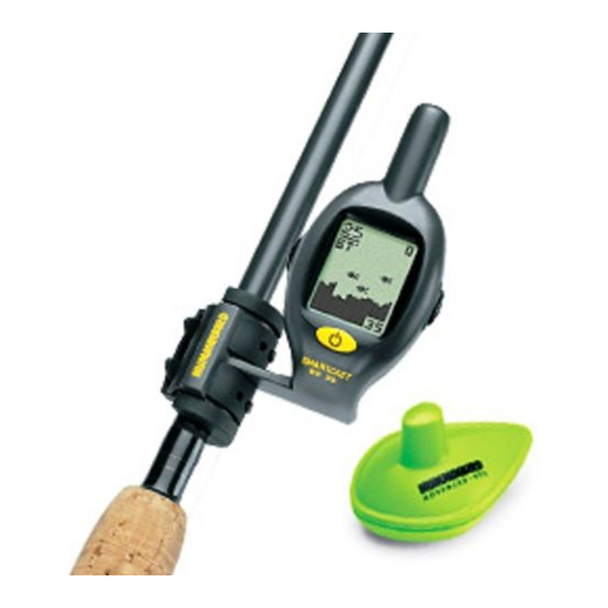
Rod Mounted Display
WARNING! This product contains lead, a chemical known to the state
of California to cause cancer, birth defects and other reproductive harm.
Sleeve Mount
WARNING! The bottom of the RSS™ should not be handled during
sonar operation, as this may cause physical discomfort and may result
in personal injury in the form of tissue damage. Handle the RSS™ only
by the antenna tower when it has been in the water.
WARNING! The RSS™ (Remote Sonar Sensor) is not intended for use
by children younger than 6 years old without adult supervision as the
RSS™ may represent a choking hazard to small children.
2. Once you have selected a specific Sleeve, attach it
Using the SmartCast
®
To scan an area,
to the Rod Mounted Display, then slip the
cast and then reel
The SmartCast
®
is a first-
assembled unit onto your rod and tighten the
in at a slow, steady
rate with your rod
of-its-kind wireless fish-
straps. Make sure that the letter on the Sleeve is
tip up.
finder that is incredibly
visible once the unit is mounted on the rod, so that
easy to use. Simply attach
the Rod Mounted Display and the Sleeve are both
the Rod Mounted Display
on the top side of the rod when you are fishing.
to your rod, then attach
NOTE: You should remove the RF25 from your rod and store it when you
the Remote Sonar Sensor
are not actively using it. See Maintenance for important storage
(RSS™) to the end of
information.
your fishing line and cast it into the water as you would
NOTE: Keep the unused Sleeves in case you get a rod of a different size.
a normal float or lure. Then power on the SmartCast
®
If you need a replacement Sleeve, you may order it from our website,
www.humminbird.com, or from participating retailers and dealers.
RF25 and you are ready to fish. The SmartCast
®
system
uses sonar technology to send sound waves from the
Attaching the RSS™
RSS™ into the water. The returned "echoes" are
The line coming from your reel can be tied off to the front
transmitted with wireless technology to the RF25 and
hole in the Remote Sonar Sensor (RSS™). If you also wish
plotted on the display. New information appears on the
to use the RSS™ as a conventional float, use the second
right. As this information moves to the left a very
hole to attach your hook using a lighter weight line. A snag
accurate picture of the underwater world is created,
will break the lighter line if you have to break free. Slip line
including objects such as the bottom, fish, and
techniques are not recommended because of the higher
structures, as well as the depth of the bottom.
risk of losing the RSS™. If you do use the slip line
NOTE: The RF25 display is designed to be used with polarized
method, use a lighter weight line after the lower stop,
sunglasses only when the user is looking straight at the screen. You
enabling retrieval of the RSS™ if the lower line with hook
may not be able to read the display from other angles when wearing
breaks away.
polarized sunglasses.
WARNING! The electronic parts in the Remote Sonar Sensor (RSS™) are
made to withstand use when casting into water.Because shock from abrupt
contact with rocks can damage your RSS™, we do NOT recommend using
your RSS™ in water that is less than one foot (0.3 m) deep.
Operational Modes
The RSS™ can be used in two distinct ways:
Sonar Graph: The RSS™can be used to create a sonar
graph of the bottom. Cast the RSS™ into the water
CAUTION: You will increase the possibility of breaking your line if you use
light test pound line on your reel. The RSS™ is positively buoyant
beyond an area of interest, then reel in the RSS™ at a
(is buoyant under its own weight plus 0.2 ounces or 5.7 g of bait and lead
slow and steady rate The digital display will provide
weight.) The maximum amount of weight for any attachment to the
precise information for bottom contour, depth and
RSS™ is approximately
structure below the RSS™. Fish and bait fish will be
the combined weight of any hook, line, weight, swivel/snap swivel and
displayed when detected.
bait that is attached to the RSS™. The RSS™ itself weighs 1 ounce
(28 g), and therefore light test line might break.
Stationary Float: The RSS™ can be used as a float in
NOTE: Store the RSS™ in a dry, non-metallic container, such as a tackle
a stationary location to monitor the area below, giving
box, in a separate compartment, and isolated from any metallic devices.
you a live update as fish approach your bait.
RSS™ Power
The Remote Sonar Sensor (RSS™) has a separate, non-
replaceable lithium battery that has a shelf life of three
years and will last for approximately 500 hours of in-water
use (when the nighttime LED is turned off). Discard the
used RSS™ in compliance with local laws as you would
any electronic component or battery.
The RSS™ will turn on its Sonar Transmitter/Receiver
automatically when it is immersed in the water. Once
®
Rod Mounted
immersed, the RSS™ will begin transmitting the sonar
information via radio frequency (RF) to the Rod Mounted
Display. The RSS™ automatically stops using power a few
seconds after being pulled out of the water.
WARNING! Do not place the RSS™ in a wet area when not in use as this
will turn on the RSS™ and shorten its usable life. Store the RSS™ in a dry
area when not in use to conserve power. Never place the RSS™ in a wet
area of a boat or on a metal surface that could accidentally power it on.
NOTE: If the RSS™ was used in salt water, rinse it with fresh water
before storing it.
Present
Depth
Temp
Fish
Bottom
Icon
Depth
Range
(see Depth Range). The display varies as the area under
the RSS™ changes.
Underwater conditions vary greatly, so some experience
and interpretation is needed to realize all the benefits of
the SmartCast
®
– use the diagram as a guide to the most
common conditions and practice using the SmartCast
over known bottom types.
The SmartCast
®
can also display the time and date.
Press the RIGHT Cursor button to momentarily view the
" diameter, while C fits rods
time and date.
LEFT Cursor
RIGHT
Button
Cursor
Assembled
Button
Display
POWER-
MENU
Button
Your RF25 has three power states:
• Off - Display is turned off
• Normal Fishing Mode - used for fishing
• Watch Mode - low-power, continuous time display.
To turn the RF25 on, press the POWER-MENU button; the
Start-Up screen will appear, then automatically change to
Normal Fishing mode if you take no further action. To turn
the RF25 off, press the POWER-MENU button until you
hear a beep (indicating that you are in Watch mode), then
press the RIGHT Cursor button to shut down the display.
Time
Date
Watch Mode
Watch mode provides a continuous time display. To enter
power-saving Watch mode, start from Normal Fishing
mode, and press and hold the POWER-MENU button until
Handle the RSS
TM
by the antenna tower
you hear a beep, then release. The time and date will be
when it has been in water.
continuously displayed, indicating that the RF25 is in
Use a heavy test line, standard
Watch mode. You can press the POWER-MENU button
knots, and tackle such as a swivel.
again to return to Normal Fishing mode.
The second leader hole is for using the RSS
TM
as a
float. Connect a lighter weight hook line to this hole.
Start-Up in Normal Fishing Mode
Do not over-weight the hook line as this will
submerge the RSS
TM
, causing signal loss.
After pressing the POWER-MENU
button to turn on the Rod Mounted
Display, you will see the Start-Up
screen. The Start-Up screen will
disappear automatically after two
to
ounces (5.3 g to 5.8 g), and includes
seconds have passed, without further
action from you. In Fishing mode, the screen will either
display sonar information or the RF25 SmartCast
will appear, indicating that no sonar information is
currently available.
When you have powered on the Rod
Mounted Display and have cast the
RSS™ into the water, returned sonar
data will start to be displayed. A vertical
line will appear first, followed by a
bottom depiction and possible fish
locations if fish are sensed.
Start-Up in Simulator Mode
To enter Simulator mode, press the
POWER-MENU button to turn on the
RF25, wait until you see the Start-up
screen, then quickly press the RIGHT
Cursor Button. Once you are in Simulator
mode, the display will show the word
Simulate, and then, after two seconds, will show simulated
data.To exit Simulator mode, you must power down the RF25.
Start-Up in Setup Mode
Use Setup to set the Time and Date.
What's On the Display
To enter Setup mode, press the
POWER-MENU button to turn on the
The SmartCast
®
displays
RF25, wait until you see the Start-Up
underwater information in an
Screen, then quickly press the RIGHT
easy to understand format.
Cursor Button twice. Once you are in
The top of the display
Setup mode, the display will briefly flash the word Setup,
corresponds to the water
then show the Time and Date.
surface, and the bottom of
the display corresponds to
Changing the Time and Date
the selected Depth Range
To change the Time and Date, enter Setup Mode (see
Start-Up in Setup Mode). When you see the Time and
Date display, the Hour digit will flash first, indicating that
you can change the hour. Once you change the hour,
you must perform all of the following steps to get to the
end of Setup mode.
®
NOTE: The flashing numeral or digit is the one that can be edited.
1. When you first enter Setup mode, press the RIGHT or
LEFT Cursor buttons repeatedly to change the hour.
Make sure that you have selected the correct hour for
the time of day (AM or PM). When the desired hour is
Powering the Display
displayed, press the POWER-MENU button to begin
editing the minutes.
ON and OFF
2. Press the RIGHT or LEFT Cursor buttons repeatedly to
If you have just
NOTE:
change the Minutes. When the desired minutes are
taken the RF25 out of the
displayed, press the POWER-MENU button to begin
box, see
Activating the Rod
editing the month.
.
Mounted Display Battery
3. Press the RIGHT or LEFT Cursor buttons repeatedly to
change the month. When the desired month is
displayed, press the POWER-MENU button to begin
editing the day.
4. Press the RIGHT or LEFT Cursor buttons repeatedly to
change the day. When the desired day is displayed,
press the POWER-MENU button to begin editing the
year.
5. Press the RIGHT or LEFT Cursor buttons repeatedly to
change the year. When the desired year is displayed,
press the POWER-MENU button to exit Setup Mode.
Activating the Backlight
Use the backlight for night fishing or low light conditions.
NOTE: The display contrast may require adjustment for optimal viewing in
NOTE: If you leave the RF25 in
low light conditions when the backlight is activated.
Normal Fishing mode for more
than 10 minutes, the unit will
Press the LEFT Cursor Button to activate the backlight.
timeout automatically and enter
Watch mode in order to save
The backlight will automatically turn off after
power.
approximately 3 seconds.
NOTE: The backlight can only be activated if the LEFT Cursor Button is
not currently being used (i.e. being used to alter a menu setting).
Viewing the Time
Pressing the RIGHT Cursor Button will display the Time
and Date.
If the RF25 is currently scrolling sonar
information, the Time and Date will be displayed, and then
the unit will automatically switch back to Sonar mode. If
the RF25 is waiting for sonar information, the Time and
Date will be displayed when the RIGHT cursor button is
pressed, and then the unit will automatically switch back
to waiting for sonar information.
Menu Features
A simple menu system accesses the adjustable features of
the SmartCast
®
RF25. To activate the menu system, press
the POWER-MENU button; the first time you do this after
power up, the Sensitivity menu choice will appear. Once the
RF25 has been powered on, pressing the POWER-MENU
button will display the last menu choice viewed. Press the
POWER-MENU button repeatedly to access other
®
screen
SmartCast
®
menu choices, one at a time. When a menu
choice is on the display, use the RIGHT and LEFT Cursor
buttons to adjust the menu settings. Menus are automatically
removed from the display after several seconds.
Sensitivity
Press the POWER-MENU button
until SENSITIVITY appears. Select a higher number to show
weaker sonar returns on the display, or a lower number
to remove clutter from the display. Adjusting Sensitivity
also affects how sonar returns are identified as Fish ID
Symbols - more fish will be detected at the highest setting
of 10, fewer at the lowest setting of 0. (0 -10, Default = 5)
The programming mode allows you to:
• turn on the blinking light
Depth Range
• switch the Advanced RSS™ Channel from A to B.
Press the POWER-MENU button
The SmartCast
until DEPTH RANGE appears. Auto is the default setting.
provides user feedback to help you make the correct
When in automatic, the lower range will be adjusted by the
selections. The temperature readout will change on the
unit to follow the bottom. Selecting a manual depth range
Control Head to 40°F (4°C), 45°F (7°C), 50°F (9°C) or
locks it to the setting you select. (Auto, 10, 15, 20, 30, 60
55°F (12°C) to signify the following settings.
or 120 feet [3, 5, 6, 10, 20, or 40 meters], Default = Auto)
NOTE: If the temperature readout is set for degrees Celsius then the
NOTE: In manual operation, if the water depth is greater than the depth
temperature readout will change on the Control Head to 4, 7, 9 or 12 to
range setting, the bottom will not be visible on the display. Select Auto to
signify the following settings:
return to automatic operation.
Depth scale changes or signal loss
Light setting:
will cause lines with missing detail
Temp changes to... Means that...
and/or abrupt changes in the
graphed bottom. When the Depth
40°F (4°C)
Range is set to Auto, the depth is set
to keep the bottom in the lower third
45°F (7°C)
of the screen. The screen image
jump shown here is due to an
automatic change in depth. New returns graphed at a
different scale will not match up with the historic data
Channel setting:
already graphed at a higher or lower scale. Vertical lines
can also occur as the radio signal from the RSS™ is lost
Temp changes to... Means that...
and then regained in rough water conditions.
50°F (9°C)
Fish Alarm
Press the POWER-MENU button
55°F (12°C)
until FISH ALARM appears. Select Off for no fish alarm, or
On for fish alarm. Fish ID must be set to On for Fish Alarm
to work. (Off,On, Default = Off)
IMPORTANT: The SmartCast
CHANNEL SELECT SetUp menu on the Control Head must be set to
Channel A (even if the RSS™ is set to Channel B) before you can see
Fish ID
the feedback on the Control Head temperature readout.
Press the POWER-MENU button
NOTE: The Advanced RSS™ programming mode will time out after 20
until FISH ID appears. Select
Raw Sonar
seconds of no user activity, display the Start-Up screen, and return the
Fish ID
RSS™ to normal operation.
either Off to view "raw" sonar
NOTE: If the temperature display returns to a normal reading, or the
returns, or On to view fish
Start-Up screen appears on the display, you are no longer in
symbols. Fish ID uses advanced
programming mode.
signal processing to interpret sonar returns and will
display a Fish Symbol when very selective requirements
How the Wet Switch™ Works
are met. Fish Alarm does not sound if Fish ID is turned off.
In the following sections, you will use the wet switch
(On, Off, Default = On)
contacts on the bottom of the Advanced RSS™ to enter
programming mode and to change the Light and Channel
Channel
settings. Before you try these procedures for the first time,
Press the POWER-MENU button
please read through this section to familiarize yourself with
until CHANNEL appears. Select either A or B to match
the way the Wet Switch™ works.
your RSS™. See Channel A and B RSS™ Units.
(A, B, Default = A)
Contrast
Press the POWER-MENU button
until CONTRAST appears. Select a setting from
1 through 10. (1 to 10, Default = 5)
Channel A and B RSS™ Units
Your SmartCast
®
unit comes with an Advanced RSS™.This
Your finger should be moist, but not dripping, before you
Advanced RSS™ may be programmed to either Channel A
touch the Wet Switch™. You can achieve the correct
or Channel B. This A/B Channel option gives you the
dampness by dipping your finger in water, then dabbing
flexibility to switch to a different channel if another angler is
your finger twice on a towel.
using a SmartCast
®
unit within 150 feet of your RSS™ to
reduce possible interference. See Changing the Channel on
A "touch" means touching both wet switch contacts at the
the Advanced RSS™ for details on selecting either Channel
same time with your moistened finger, using medium
A or Channel B.
pressure. The time between touches needs to be one
second or less.
NOTE: RSS™ units, regardless of channel, may generate erratic depth
readings as a result of sonar interference when used in close proximity
NOTE: Your finger must make contact with both of the wet switch pins
(closer than 40 feet) to each other or to other sonar devices.
simultaneously in order to tap them successfully.
Understanding the Advanced RSS™
See the procedures that follow for specific instructions
The Advanced RSS™ provides the following functionality:
on turning the light on or off or changing the channel
from A to B.
• Water Surface Temperature
• Blinking Light for nighttime use
Turning on the Advanced RSS™ Blinking Light
• A/B Channel Select.
To turn on the blinking nighttime fishing light:
Water temperature will be displayed automatically on
1. Wet your finger and tap the wet switch on the
the screen.
Advanced RSS™ three times (the time between
You must manually program the Advanced RSS™ in
touches needs to be one second or less) to enter
order to turn the light on or off or to change the RSS™
the Light programming mode. The temperature
channel setting to A or B.
reading on the Control Head will change to show
a temperature reading of 40°F (4°C) (blinking
Default settings on new products are Light = OFF and
light OFF).
Channel = A.
RSS™ Programming Mode
You may change the light setting or the channel type on
the Advanced RSS™ using a programming mode that is
accessed by touching the wet switch contacts on the
bottom of the RSS™.
NOTE: Please read this and the next section BEFORE you try to program
the Advanced RSS™ using the wet switch contacts. Specific step-by-
step procedures to turn on the light and to change the channel follow this
Temperature of 40
section. You will find it easier to perform these steps once you have
Means LED is OFF
grasped the way the programming mode works.
®
Control Head temperature readout
Blinking light is OFF (factory default)
Blinking light is ON (but only blinks
when the Advanced RSS™ is in the
water)
RSS™ is set to CHANNEL A
(factory default)
RSS™ is set to CHANNEL B
®
Control Head must be turned on and the
Temperature Setting of 45
Means LED is On
Advertisement

Related Manuals for Humminbird RF25 SmartCast


Summary of Contents for Humminbird RF25 SmartCast
- Page 1 • This RF25 SmartCast ® Operations Manual. NOTE: Your RF25 will start up in Watch mode after the battery is installed initially. See Powering the Display ON and OFF and Watch Mode for more If any of these components are missing, please contact information.
- Page 2 Rod Mounted Display, the reception may be lost. the new channel designation on the Advanced RSS™. See Channel Select (SetUp Menu) for • The RF25 depth range is 2 to 120 feet (0.6 to 35 more information. meters). Erratic readings may occur in water that is CAUTION: Make sure that you change the Channel Selection on the shallower than 2 feet (0.6 m).