Cisco ME 3400 Hardware Installation Manual
Cisco systems ethernet access switch installation guide
Hide thumbs
Also See for Cisco ME 3400:
- Software configuration manual (1138 pages) ,
- Command reference manual (950 pages) ,
- Getting started manual (33 pages)
Table of Contents
Advertisement
Advertisement
Table of Contents

Related Manuals for Cisco Cisco ME 3400


Summary of Contents for Cisco Cisco ME 3400
- Page 1 Cisco ME 3400 Ethernet Access Switch Hardware Installation Guide August 2007 Americas Headquarters Cisco Systems, Inc. 170 West Tasman Drive San Jose, CA 95134-1706 http://www.cisco.com Tel: 408 526-4000 800 553-NETS (6387) Fax: 408 527-0883 Text Part Number: OL-7677-04...
- Page 2 OR ITS SUPPLIERS HAVE BEEN ADVISED OF THE POSSIBILITY OF SUCH DAMAGES. CCVP, the Cisco logo, and the Cisco Square Bridge logo are trademarks of Cisco Systems, Inc.; Changing the Way We Work, Live, Play, and Learn is a service mark of Cisco Systems, Inc.;...
-
Page 3: Table Of Contents
Setting up the Switch Switch Models Front Panel Description Cisco ME 3400-24TS AC and DC Switches Front Panel Cisco ME 3400-24FS Switch AC Switch Front Panel Cisco ME 3400G-12CS AC and DC Switches Front Panel Cisco ME 3400G-2CS Switch Front Panel... - Page 4 Connecting to the 10/100 and 10/100/1000 Ports Connecting to SFP Modules Connecting to Fiber-Optic SFP Modules Connecting to 1000BASE-T SFP Modules Connecting to Dual-Purpose Ports Where to Go Next Cisco ME 3400 Ethernet Access Switch Hardware Installation Guide 1-13 1-14 1-14 1-14 1-14...
- Page 5 Adapter Pinouts Technical Specifications A P P E N D I X Connecting to DC Power A P P E N D I X Preparing for Installation Grounding the Switch OL-7677-04 Cisco ME 3400 Ethernet Access Switch Hardware Installation Guide Contents...
- Page 6 A P P E N D I X Accessing the CLI Through the Console Port Starting the Terminal-Emulation Software Entering the Initial Configuration Information IP Settings Completing the Setup Program N D E X Cisco ME 3400 Ethernet Access Switch Hardware Installation Guide OL-7677-04...
-
Page 7: Preface
LEDs. Chapter 2, “Switch Installation,” switch in a rack, on a wall, on a table, or on a shelf, and how to make port connections. Chapter 3, “Troubleshooting,”... -
Page 8: Conventions
The safety warnings for this product are translated into several languages in the Regulatory Compliance and Safety Information for the Cisco ME 3400 and ME 2400 Ethernet Access Switches that ships with the product. The EMC regulatory statements are also included in that guide. -
Page 9: Related Publications
These documents provide complete information about the switch and are available from this Cisco.com site: http://www.cisco.com/en/US/products/ps6580/tsd_products_support_series_home.html Release Notes for the Cisco ME 3400 Ethernet Access Switch (not orderable but available on • Cisco.com) Before installing, configuring, or upgrading the switch, see the release notes on Cisco.com for Note the latest information. -
Page 10: Obtaining Documentation, Obtaining Support, And Security Guidelines
Cisco documents, see the monthly What's New in Cisco Product Documentation, which also lists all new and revised Cisco technical documentation, at this URL: http://www.cisco.com/en/US/docs/general/whatsnew/whatsnew.html Cisco ME 3400 Ethernet Access Switch Hardware Installation Guide Preface OL-7677-04... -
Page 11: Chapter 1 Product Overview
• Setting up the Switch See the Cisco ME 3400 and Cisco ME 2400 Ethernet Access Switches Getting Started Guide that shipped with the switch for instructions on how to initially configure your switch. The getting started guide also covers switch management options, basic rack-mounting procedures, port and module connections, power connection procedures, and troubleshooting help. -
Page 12: Front Panel Description
ME 3400G-2CS Front Panel Description The switch front panel includes the 10/100 ports or dual-purpose ports (that you can configure as either 10/100/1000 Ethernet ports that use RJ-45 connectors or for SFP modules), dedicated SFP module ports, switch LEDs, power connectors, and the console port. -
Page 13: Cisco Me 3400-24Ts Ac And Dc Switches Front Panel
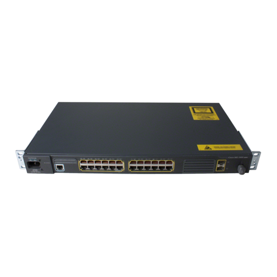
Cisco ME 3400G-24TS AC switch front panel. Cisco ME 3400G-24TS DC switch front panel. The 10/100 Fast Ethernet ports are grouped in pairs. The first member of the pair (port 1) is above the second member (port 2) on the left. Port 3 is above port 4, and so on. -
Page 14: Cisco Me 3400-24Fs Switch Ac Switch Front Panel
Front Panel Description Cisco ME 3400-24FS Switch AC Switch Front Panel The Cisco ME 3400-24FS AC switch has 24 100BASE-FX SFP module ports and 2 Gigabit Ethernet SFP module ports, as shown in member (port 2) on the left. Port 3 is above port 4, and so on. The Gigabit Ethernet uplink SFP module ports are numbered 1 above and 2 below. -
Page 15: Cisco Me 3400G-2Cs Switch Front Panel
Power supply 1 and 2 LEDs Cisco ME 3400G-2CS Switch Front Panel The Cisco ME 3400G-2CS switch has two dual-purpose ports, numbered 1 and 2, as shown in Figure 1-6. You can configure the dual-purpose ports as either 10/100/1000 ports that use RJ-45 connectors or configure them for SFP modules. -
Page 16: 10/100 Ports (Only The Cisco Me-3400-24Ts Switches)
10/100 Ports (Only the Cisco ME-3400-24TS Switches) You can set the 10/100 ports on the Cisco ME 3400-24TS switches to operate in any combination of half duplex, full duplex, or 10 or 100 Mb/s. You can set the ports for speed and duplex autonegotiation, in compliance with IEEE 802.3ab. -
Page 17: Sfp Module Ports
The 10/100 Fast Ethernet ports and the dual-purpose ports on Cisco ME 3400-12CS and Cisco ME 3400-2CS switches are configured as UNIs. The SFP module uplink ports are configured as NNIs. If the switch is running the metro base or metro access image, you can configure only four ports on the switch as NNIs at one time, but you can configure all ports on the switch as UNIs. -
Page 18: Sfp Module Patch Cable
You can order the SFP module patch cable (part number CAB-SFP-50CM=). LEDs You can use the switch System and port LEDs to monitor switch activity and performance. The LEDs are described in these sections: System LED, page 1-8 •... - Page 19 S Y S T C O N S O System LED OL-7677-04 Cisco ME 3400-24TS and Cisco ME 3400-24FS Switches System LED S Y S T E M C O N S O Cisco ME 3400G-12CS Switch System LED S Y S T E M...
- Page 20 The Cisco ME 3400G-12CS switches have power supply LEDs labeled PS1 and PS2, as shown Figure 1-11. The lit LED shows which power supply is on. AC switch. The PS LEDs for a DC switch are in the same position on the front panel. Figure 1-11 P S 1...
-
Page 21: Dual-Purpose Port Leds
The LED colors have the same meanings as described in Console Port You can connect the switch to a PC by means of the console port and an RJ-45-to-DB-9 female cable. If you want to connect the switch console port to a terminal, you need to provide an RJ-45-to-DB-25 female DTE adapter. -
Page 22: Rear Panel Description
• Cisco ME 3400-2CS Switch Rear Panel, page 1-13 Cisco ME 3400-24TS Switch Rear Panel The rear panel on the Cisco ME 3400-24TS switch has a cable lock, an exhaust fan, and a ground connector. (See Figure 1-13 Cable lock... -
Page 23: Cisco Me 3400G-12S Switch Rear Panel
Chapter 1 Product Overview Cisco ME 3400G-12S Switch Rear Panel The rear panel on the Cisco ME 3400G-12CS switch has a cable lock, two exhaust fans, and a ground connector. (See has a failed fan as soon as possible. Figure 1-15... -
Page 24: Cisco Me Ac Switch Power Supply
Cisco ME AC Switch Power Supply The Cisco ME AC switch is powered through an internal power supply. The AC power supply is an autoranging unit that supports input voltages between 100 and 240 VAC. Use the supplied AC power cord to connect the AC power connector to an AC power outlet. -
Page 25: Switch Installation
• Warnings These warnings are translated into several languages in the Regulatory Compliance and Safety Information for the Cisco ME 3400 and Cisco ME 2400 Ethernet Access Switches document that ships with the switch. Warning Before working on equipment that is connected to power lines, remove jewelry (including rings, necklaces, and watches). -
Page 26: Chapter 2 Switch Installation
Contact the appropriate electrical inspection authority or an electrician if you are uncertain that suitable grounding is available. Statement 1024 Cisco ME 3400 Ethernet Access Switch Hardware Installation Guide Chapter 2 Switch Installation... - Page 27 To comply with the Telcordia GR-1089 Network Equipment Building Systems (NEBS) standard for electromagnetic compatibility and safety, connect the Ethernet cables only to intrabuilding or nonexposed wiring or cabling. OL-7677-04 Cisco ME 3400 Ethernet Access Switch Hardware Installation Guide Preparing for Installation...
-
Page 28: Cisco Me 3400-24Ts Switches
Airflow around the switch and through the vents is unrestricted. • If the switch is installed in a closed or multirack assembly, the temperature around it might be Note greater than normal room temperature. Cisco ME 3400 Ethernet Access Switch Hardware Installation Guide Chapter 2 “Cable and Adapter Specifications”... -
Page 29: Verifying Switch Operation
50 W (typical), 65 W (maximum), 171 BTUs per hour (typical), 222 BTUs per hour (maximum) Verifying Switch Operation Before installing the switch in a rack, on a wall, or on a table or shelf, you should power the switch and verify that the switch passes POST. -
Page 30: Rack-Mounting
The kit part number is RCKMNT-1RU= (700-12398-XX). Removing Screws from the Switch If you plan to install the switch in a rack, you must first remove the screws in the switch chassis so that you can attach the mounting brackets. -
Page 31: Attaching Brackets To The Switch
24-inch rack-mounting brackets ETSI-rack brackets Figure 2-3 on page Figure 2-5 on page Cisco ME 3400 Ethernet Access Switch Hardware Installation Guide Installing the Switch shows the standard types of mounting 2-8. For the Cisco ME 3400G-2CS Figure 2-4 on page 2-9. - Page 32 19-inch racks on all except the Cisco ME 3400G-2CS switch. Figure 2-3 Phillips flat-head screws Front-panel facing forward Cisco ME 3400 Ethernet Access Switch Hardware Installation Guide Attaching Brackets to 19-Inch Racks C is co M E 34 00 SE RIE S...
- Page 33 Cisco ME 3400G-2CS switch. Figure 2-4 Attaching Brackets to 19-Inch Racks on the Cisco ME 3400G-2CS Switch SYS T C is co M E 34 00 CO NS OL SE RIE Cisco ME 3400 Ethernet Access Switch Hardware Installation Guide OL-7677-04...
- Page 34 23-inch racks on all except the Cisco ME 3400G-2CS switch: Figure 2-5 Phillips flat-head screws Front-panel facing forward 4 Cisco ME 3400 Ethernet Access Switch Hardware Installation Guide 2-10 Attaching Brackets for 23- and 24-Inch Racks C is co M E 34 00...
- Page 35 Attaching Brackets for 24-Inch Racks C is co M E 34 00 SE RIE S C is co M E 34 00 SE RIE S Rear-panel facing forward Telco-rack mount Cisco ME 3400 Ethernet Access Switch Hardware Installation Guide Installing the Switch 2-11...
-
Page 36: Attaching Brackets For Etsi Racks
Figure 2-7 shows how to attach brackets for ETSI racks: Figure 2-7 Phillips flat-head screws Front-panel facing forward Cisco ME 3400 Ethernet Access Switch Hardware Installation Guide 2-12 Attaching Brackets for ETSI Racks C is co M E 34 00... -
Page 37: Mounting The Switch In A Rack
Switch Installation Mounting the Switch in a Rack After the brackets are attached to the switch, use the four supplied number-12 Phillips machine screws to securely attach the brackets to the rack, as shown in the Cisco ME 3400G-2CS switch. -
Page 38: Wall-Mounting
Connect to the RJ-45 connector of a dual-purpose port and run the Initial Configuration Dialog. See • the Cisco ME 3400 and ME 2400 Ethernet Access Switches Getting Started Guide for instructions. Connect to the front-panel ports. See the •... -
Page 39: Mounting The Switch On A Wall
Mounting the Switch on a Wall For the best support of the switch and cables, make sure the switch is attached securely to wall studs or to a firmly attached plywood mounting backboard. Mount the switch with the front panel facing up, as... -
Page 40: Table- Or Shelf-Mounting
Place the switch on the table or shelf near an AC power source. Step 1 After the switch is placed on the table or shelf, you need to do these tasks to complete the installation: Step 2 Power on the switch. See the •... -
Page 41: Installing Sfp Modules
SFP Module with a Bale-Clasp Latch Figure 2-13). Installing an SFP Module into an SFP Module Slot C is co M E 3 4 0 0 SE RI ES Cisco ME 3400 Ethernet Access Switch Hardware Installation Guide Installing and Removing SFP Modules 2-17... -
Page 42: Removing Sfp Modules
Grasp the SFP module between your thumb and index finger, and carefully remove it from the Step 4 module slot. Cisco ME 3400 Ethernet Access Switch Hardware Installation Guide 2-18 Figure Removing a Bale-Clasp Latch SFP Module by Using a Flat-Blade Screwdriver... -
Page 43: Inserting And Removing The Sfp Module Patch Cable
Insert the SFP module patch cable into the slot until you feel the connector on the cable snap into place Step 2 in the rear of the slot (see Figure 2-15 Repeat these steps for the second Cisco ME switch to which you want to cascade the first switch. Step 3 Figure 2-16. -
Page 44: Connecting To The 10/100 And 10/100/1000 Ports
Therefore, you can use either a crossover or a straight-through cable for connections to a copper 10/100, 10/100/1000, or 1000BASE-T SFP module port on the switch, regardless of the type of device on the other end of the connection. -
Page 45: Connecting To Sfp Modules
Connecting to a Fiber-Optic SFP Module Port C is co M E 3 4 0 0 SE RI ES Cisco ME 3400 Ethernet Access Switch Hardware Installation Guide Connecting to SFP Modules section. For instructions on how to “Connecting to 1000BASE-T SFP Modules”... -
Page 46: Connecting To 1000Base-T Sfp Modules
Therefore, you can use either a crossover or a straight-through cable for connections to a copper 10/100, 10/100/1000, or 1000BASE-T SFP module port on the switch, regardless of the type of device on the other end of the connection. -
Page 47: Connecting To Dual-Purpose Ports
Step 4 Connecting to Dual-Purpose Ports You can configure the dual-purpose ports on the Cisco ME 3400G-12CS and Cisco ME 3400-2CS switches as either 10/100/1000 ports or as SFP module slots. Cisco ME 3400G-12CS switch dual-purpose ports. This section also applies to the Cisco ME 3400-2CS switches. -
Page 48: Where To Go Next
Use the CLI from the console to configure the switch. See the switch software configuration guide • or the switch command reference on for information about using the CLI with a Cisco ME switch. For setup instructions that use the CLI setup program, go to with the CLI-Based Setup Program.”... - Page 49 • Check Switch POST Results As the switch powers on, it begins the POST, a series of tests that runs automatically to ensure that the switch functions properly. It might take several minutes for the switch to complete POST. When the switch begins POST, the system LED slowly blinks green. When POST completes, the system LED blinks amber.
-
Page 50: Chapter 3 Troubleshooting
Diagnosing Problems Check Switch LEDs You must have physical access to the switch to do this. Look at the port LEDs for troubleshooting information about the switch. See the and their meanings. Check Switch Connections Review this section when troubleshooting switch connectivity problems. -
Page 51: Sfp Module Port Issues
Ping the End Device Check the end device by pinging it from the directly connected switch first, and then work your way back port by port, interface by interface, trunk by trunk, until you find the source of the connectivity issue. -
Page 52: Check Switch Performance
A common issue with speed and duplex occurs when the duplex settings are mismatched between two switches, between a switch and a router, or between the switch and a workstation or server. This can happen when you manually set the speed and duplex or because of autonegotiation issues between the two devices. -
Page 53: Locating The Switch Serial Number
If you contact Cisco Technical Assistance, you need to know the serial number of your switch. Use these figures to locate the serial number on your switch. You can also use the show version command to get the serial number. - Page 54 Locating the Switch Serial Number Figure 3-3 Figure 3-4 Cisco ME 3400 Ethernet Access Switch Hardware Installation Guide Serial Number Location on the Cisco ME 3400G-2CS Switch SN: XXXNNNNXXXX Serial Number Location on the Cisco ME 3400-24FS Switch SN: XXXNNNNXXXX...
-
Page 55: Appendix
• 10/100 Ports The Cisco ME 3400-24TS 10/100 Ethernet ports use standard RJ-45 connectors and Ethernet pinouts with internal crossovers. These ports have the send (TD) and receive (RD) signals internally crossed so that a twisted-pair straight-through cable and adapter can be attached to the port. - Page 56 Therefore, you can use either a crossover or a straight-through cable for connections to a copper 10/100, 10/100/1000, or 1000BASE-T SFP module port on the switch, regardless of the type of device on the other end of the connection.
-
Page 57: Sfp Module Ports
PC. You need to provide a RJ-45-to-DB-25 female DTE adapter if you want to connect the switch console port to a terminal. You can order a kit (part number ACS-DSBUASYN=) containing that adapter from Cisco. For console port and adapter pinout... -
Page 58: Cable And Adapter Specifications
1490 TX (GLC-BX-D) 1310 RX 1000BASE-BX10-U 1310 TX (GLC-BX-U) 1490 RX 1000BASE-SX (GLC-SX-MM) 1000BASE-LX/LH 1310 (GLC-LH-SM) Cisco ME 3400 Ethernet Access Switch Hardware Installation Guide Core Size/Cladding Modal Bandwidth Fiber Type Size (micron) (MHz/km) G.652 — 50/125 62.5/125 50/125 62.5/125 G.652... -
Page 59: Two Twisted-Pair Cable Pinouts
2 TD– Two Twisted-Pair Crossover Cable Schematic Switch 3 TD+ 6 TD– 1 RD+ 2 RD– Cisco ME 3400 Ethernet Access Switch Hardware Installation Guide Cable and Adapter Specifications Modal Bandwidth (MHz/km) Cable Distance — 43.4 to 62 miles (70 to 100 km) —... -
Page 60: Four Twisted-Pair Cable Pinouts For 1000Base-T Ports
The wire connected to the pin on the outside of the left plug should be the same color as the wire connected to the pin on the outside of the right plug. (See Cisco ME 3400 Ethernet Access Switch Hardware Installation Guide Figure A-7... -
Page 61: Adapter Pinouts
RJ-45-to-DB-25 female DTE adapter, and the console device. Note The RJ-45-to-DB-25 female DTE adapter is not supplied with the switch. You can order a kit (part number ACS-DSBUASYN=) containing this adapter from Cisco. OL-7677-04... - Page 62 Cable and Adapter Specifications Table A-3 Console Port Signaling Using a DB-25 Adapter Switch Console Port (DTE) Signal Cisco ME 3400 Ethernet Access Switch Hardware Installation Guide RJ-45-to-DB-25 Console Terminal Adapter Device DB-25 Pin Signal Appendix A Connector and Cable Specifications...
-
Page 63: Appendix
Technical Specifications This appendix lists the switch technical specifications: Table B-1, Technical Specifications for the Cisco ME 3400-24TS AC and DC Ethernet Access • Switch Table B-2, Technical Specifications for the Cisco ME 3400-24FS AC Ethernet Access Switch • Table... - Page 64 Table B-2 Technical Specifications for the Cisco ME 3400-24FS AC Ethernet Access Switch Environmental Ranges Operating temperature Storage temperature Relative humidity Operating altitude Storage altitude AC Power Requirements AC input voltage Power consumption Power rating Physical Dimensions Weight Dimensions (H x D x W)
- Page 65 15 W (typical), 20 W (maximum), 51 BTUs per hour (typical), 68 BTUs per hour (maximum) 0.04 KVA 3.5 lb (1.6 kg) 1.73 x 7.1 x 10.6 in. (4.4 x18.2 x 26.9 cm) Cisco ME 3400 Ethernet Access Switch Hardware Installation Guide...
- Page 66 Appendix B Technical Specifications Cisco ME 3400 Ethernet Access Switch Hardware Installation Guide OL-7677-04...
-
Page 67: Appendix
Ratcheting torque screwdriver with a Phillips head that exerts up to 15 pound-force inches (lbf-in.) • of pressure Panduit crimping tool with optional controlled cycle mechanism (model CT-700, CT-720, CT-920, • CT-920CH, CT-930, or CT-940CH) OL-7677-04 A P P E N D I X Cisco ME 3400 Ethernet Access Switch Hardware Installation Guide... -
Page 68: Grounding The Switch
Preparing the Ground Wire Before you ground the switch to earth ground, you must prepare the ground wire. Follow these steps. Make sure to follow any grounding requirements at your site. Locate the ground lug and the two number-10-32 screws. A ground lug and screws are located both on Step 1 the front panel and on the rear panel of the switch. - Page 69 [ozf-in.]). OL-7677-04 Stripping the Ground Wire Wire lead Insulation Crimping the Ground Lug Figure C-3 shows how to torque the ground screws on a Cisco ME DC switch. Cisco ME 3400 Ethernet Access Switch Hardware Installation Guide Grounding the Switch...
- Page 70 Appendix C Connecting to DC Power Grounding the Switch Figure C-3 Torquing Ground-Lug Screws Torque to 15 lbf-in. Cisco ME 3400 Ethernet Access Switch Hardware Installation Guide OL-7677-04...
-
Page 71: Connecting The Grounding Wire To Earth Ground
Connecting the Grounding Wire to the Rack from the Rear-Panel Ground Connector Telco rack OL-7677-04 Grounding wire Grounding wire Cisco ME 3400 Ethernet Access Switch Hardware Installation Guide Grounding the Switch Figure C-5), but not to both. Ci sco M... -
Page 72: Wiring The Dc-Input Power Source
Before you wire the DC-input power source, review the warnings in this section and this information: If the switch software detects that the circuit boards are not receiving power from an internal power supply, the software sends a message like this to the console:... -
Page 73: Cisco Me 3400-24Ts Switches
(See the example in configuration provides redundant power, and the switch continues to operate if one of the external power supplies fails. However, the software does not send a message to you that an internal power supply has failed. - Page 74 Warning Statement 1030 You must connect the Cisco ME DC switch only to a DC-input power source with –36 to –72 VDC Caution supply voltage. If the supply voltage is not in this range, the switch might not operate properly or might be damaged.
- Page 75 Appendix C Connecting to DC Power The front panel of the switch shows the positive and negative positions for both the A and B feed wires (See Figure C-9, which shows a Cisco ME 3400-24TS-DC switch.) Figure C-9 IN P U T - 3 6 –...
- Page 76 Step 7 Repeat Steps 4 and 5 for the remaining three DC-input power source wires. completed wiring of a terminal block plug. Cisco ME 3400 Ethernet Access Switch Hardware Installation Guide C-10 Inserting Wires in the Terminal Block Plug Figure C-12.)
- Page 77 Appendix C Connecting to DC Power Figure C-13 Return (positive) Feed A Supply (negative) Feed A Insert the terminal block plug in the terminal block header on the front panel of the switch. Step 8 (See Figure C-14). Secure the wires coming in from the terminal block so that they cannot be disturbed by casual contact.
- Page 78 Appendix C Connecting to DC Power Wiring the DC-Input Power Source Cisco ME 3400 Ethernet Access Switch Hardware Installation Guide C-12 OL-7677-04...
-
Page 79: Appendix
Accessing the CLI Through the Console Port You can access the CLI on a configured or unconfigured switch by connecting the console port of the switch to the serial port on your PC or workstation and accessing the switch through a Telnet session. -
Page 80: Entering The Initial Configuration Information
Entering the Initial Configuration Information To power on the switch, connect one end of the AC power cord to the AC power connector on the switch, and connect the other end of the power cord to an AC power outlet. - Page 81 Subnet mask for this interface [255.0.0.0]: 255.0.0.0 Step 9 Enter Y to configure the switch as the cluster command switch. Enter N to configure it as a member switch or as a standalone switch. If you enter N, you can configure the switch as a command switch later through the CLI. To configure it later, enter no.
- Page 82 If you are using a Cisco ME 3400-12CS switch with a single power supply, enter the no power-supply dual global configuration command so that the switch does not send an alarm that the second power supply is not operating.
-
Page 83: I N D E X
1000BASE-T ports two twisted-pair pinout See also connectors and cables cabling 10/100/1000 ports 10/100 ports auto-MDIX pinouts See also connectors and cables cautions viii Cisco ME 3400 Ethernet Access Switch Hardware Installation Guide 2-14 2-22 2-20 2-20, B-2 2-22 IN-1... -
Page 84: Ports B
1000BASE-T ports CWDM SFP module DC connectors, ordering replacements DC power Cisco ME 3400-G-12CS switch connecting to 2-5, D-2 Cisco ME 3400 Ethernet Access Switch Hardware Installation Guide IN-2 1-14 installing specifications warning dense wavelength-division multiplexing See DWDM... -
Page 85: Link Status
NEBS compliance network configuration examples Network Equipment Building Systems See NEBS compliance noise, electrical overcurrent protection warning overheating warning Cisco ME 3400 Ethernet Access Switch Hardware Installation Guide 1-10 3-1 to 3-2 2-16 2-16 2-14 2-8 to 2-9 2-10... - Page 86 AC power outlet 1-14 procedures connection 2-20 to 2-23 installation 2-5 to 2-16 product disposal warning Cisco ME 3400 Ethernet Access Switch Hardware Installation Guide IN-4 PS1 and PS2 LEDs publications, related rack-mounting rack-mounting warning rear panel clearance...
- Page 87 Ethernet cables short-circuit (overcurrent) protection short-circuit protection Cisco ME 3400 Ethernet Access Switch Hardware Installation Guide Index 3-1 to 3-2 2-14 2-2, 2-15 viii 2-2, C-2 2-3, C-2 2-1, C-8...
- Page 88 Index warnings (continued) stacking chassis trained and qualified personnel two-poled disconnect device wall-mounting 2-2, 2-15 Cisco ME 3400 Ethernet Access Switch Hardware Installation Guide IN-6 OL-7677-04...