Cisco Catalyst 3550 Getting Started Manual
Cisco systems multilayer switch getting started guide
Hide thumbs
Also See for Catalyst 3550:
- Command reference manual (794 pages) ,
- Installation manual (154 pages) ,
- Hardware installation manual (106 pages)
Table of Contents
Advertisement
Catalyst 3550 Multilayer Switch Getting Started Guide
INCLUDING LICENSE AND WARRANTY
1
About this Guide
2
Taking Out What You Need
3
Running Express Setup
4
Managing the Switch
5
Rack-Mounting
6
Connecting to DC Power
7
In Case of Difficulty
8
Obtaining Documentation
9
Obtaining Technical Assistance
10
Cisco Limited Lifetime Hardware Warranty Terms
Getting Started Guide
Advertisement
Table of Contents

Related Manuals for Cisco Catalyst 3550


Summary of Contents for Cisco Catalyst 3550
- Page 1 Catalyst 3550 Multilayer Switch Getting Started Guide INCLUDING LICENSE AND WARRANTY About this Guide Taking Out What You Need Running Express Setup Managing the Switch Rack-Mounting Connecting to DC Power In Case of Difficulty Obtaining Documentation Obtaining Technical Assistance Cisco Limited Lifetime Hardware Warranty Terms...
-
Page 2: About This Guide
“Obtaining Documentation” section on page 23. For translations of the warnings that appear in this publication, refer to the Regulatory Compliance and Safety Information for the Catalyst 3550 Multilayer Switch that accompanies this guide. Taking Out What You Need Follow these steps: 1. -
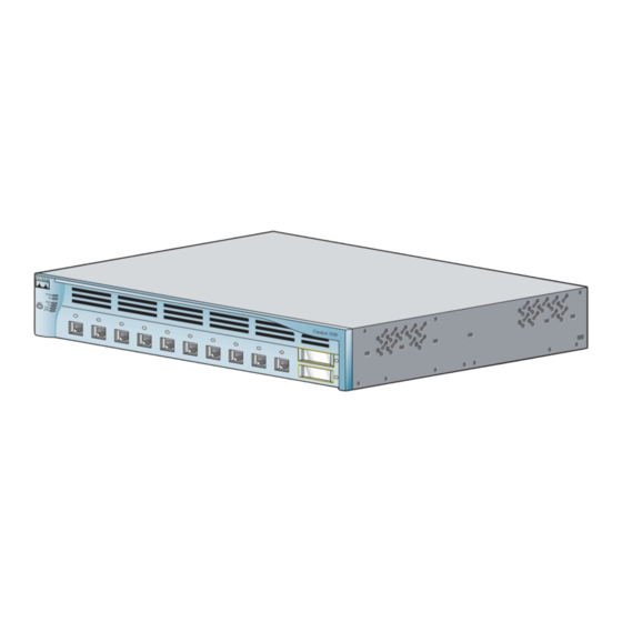
Page 3: Shipping Box Contents
Shipping Box Contents SYS TEM MOD E STAT US UTIL DUP LX SPE ED Catalyst 3550 switch Two 19-inch mounting brackets Console cable AC power cord (AC-powered switches only) Documentation Four rubber mounting feet C at al ys t 35 50... -
Page 4: Running Express Setup
Running Express Setup When you first set up the switch, you should use Express Setup to enter the initial IP information. This enables the switch to connect to local routers and the Internet. You can then access the switch through the IP address for further configuration. - Page 5 Step 7 Category 5 Ethernet cable (not provided) to any 10/100 or 10/100/1000 Ethernet port on the switch front panel and to the Ethernet port on the PC. Step 8 Verify that the LEDs on both Ethernet ports are green.
- Page 6 IP information. The VLAN ID range is 1 to 1001. • In the IP Address field, enter the IP address of the switch. In the IP Subnet Mask field, click the drop-down arrow, and select an IP Subnet Mask.
-
Page 7: Refreshing The Pc Ip Address
Using the Device Manager The simplest way to manage the switch is by using the device manager that is in the switch memory. This is an easy-to-use web interface that offers quick configuration and monitoring. You can access the device manager from anywhere in your network through a web browser. -
Page 8: Downloading Cisco Network Assistant
Command-Line Interface You can enter Cisco IOS commands and parameters through the CLI. Access the CLI either by connecting your PC directly to the switch console port or through a Telnet session from a remote PC or workstation. Follow these steps: 1. -
Page 9: Rack Mounting
This section covers basic 19-inch rack-mounting and switch port connections. The illustrations in this section show the Catalyst 3550-12T and 3550-24 switch for examples. You can install and connect other Catalyst 3550 switches as shown in these illustrations. For alternate mounting procedures, such as installing the switch in a 24-inch rack or on a wall, and for additional cabling information, refer to the Catalyst 3550 Multilayer Switch Hardware Installation Guide on Cisco.com. -
Page 10: Installation Warning Statements
This section includes the basic installation warning statements. Warning To prevent the switch from overheating, do not operate it in an area that exceeds the maximum recommended ambient temperature of 113°F (45°C). To prevent airflow restriction, allow at least 3 inches (7.6 cm) of clearance around the ventilation openings. - Page 11 UL-listed lug suitable for number-6 AWG wire and two number-10-32 ground-lug screws. You must connect the Catalyst 3550-24-DC switch only to a DC-input power source that Caution has an input supply voltage from –36 to –72 VDC. If the supply voltage is not in this range, the switch might not operate properly or might be damaged.
-
Page 12: Attaching The Brackets
Attaching the Brackets Use four Phillips flat-head screws to attach the long side of the brackets on the Catalyst 3550-12 switches. SYS TEM MO DE STA TUS UTI L DUP LX SPE ED SYS TEM MO DE STA TUS UTI L... - Page 13 Attaching the Brackets Use six Phillips flat-head screws to attach the long side of the brackets on the Catalyst 3550-24 and 3550-48 switches. SYS TEM STA TUS UTI L DU PLX SPE ED MO DE SYS TEM STA TUS UTI L...
-
Page 14: Rack-Mount The Switch
Rack-Mount the Switch Use the black Phillips machine screw to attach the cable guide to the left or right bracket. Use the four number-12 Phillips machine screws to attach the brackets to the rack. Cable guide SYS TEM MO DE... -
Page 15: Connect To The Switch Ports
Insert the other cable end into an RJ-45 connector on the other device. Step 2 The Catalyst 3550-24PWR switch 10/100 inline power ports, also referred to as pre-standard Power over Ethernet (PoE) ports, provide –48 VDC power and protocol support for Cisco IP Phones and Cisco Aironet Access points. - Page 16 Install and Connect to GBIC Module Ports Follow these steps: Grasp the module on the sides, and Step 1 insert it into the switch slot until you feel the connector snap into place. Insert an appropriate cable into the Step 2 module port.
-
Page 17: Connecting To Dc Power
See the “In Case of Difficulty” section on page 20 for information about online assistance. Connecting to DC Power To connect the Catalyst 3550-24-DC switch to a DC-input power source, follow the steps in this section. Equipment That You Supply You need to supply these tools and equipment: •... -
Page 18: Wiring The Dc Input Power Source
Using the ratcheting screwdriver, torque the ground lug screws to 15 lbf-in. (240 Step 4 ounce-force inches [ozf-in.]) to attach the ground lug to the switch. Wiring the DC Input Power Source Follow these steps: On the terminal block connector, identify the positive and negative feed positions. - Page 19 Move the circuit-breaker handle for the DC power source to the on position. Step 6 You must connect the Catalyst 3550-24-DC switch only to a DC-input power source that Caution has an input supply voltage from –36 to –72 VDC. If the supply voltage is not in this range, the switch might not operate properly or might be damaged.
-
Page 20: In Case Of Difficulty
In Case of Difficulty If you experience difficulty, help is available here and on Cisco.com. This section includes Express Setup troubleshooting, how to reset the switch, how to access help online, and where to find more information. Troubleshooting Express Setup If Express Setup does not run, or if the Express Setup page does not appear in your browser: •... -
Page 21: Resetting The Switch
Express Setup as described in the “Running Express Setup” section on page 4. Accessing Help Online First look for a solution to your problem in the troubleshooting section of the Catalyst 3550 Multilayer Switch Hardware Installation Guide or the Catalyst 3550 Multilayer Switch Software Configuration Guide on Cisco.com. -
Page 22: For More Information
4. Click the subject that addresses the problem that you are experiencing. For More Information For more information about the switch, refer to these documents on Cisco.com: • Catalyst 3550 Multilayer Switch Hardware Installation Guide (not orderable but available on Cisco.com). This guide provides complete hardware descriptions and detailed installation procedures. -
Page 23: Obtaining Documentation
Ordering tool: http://www.cisco.com/en/US/partner/ordering/index.shtml • Nonregistered Cisco.com users can order documentation through a local account representative by calling Cisco Systems Corporate Headquarters (California, USA) at 408 526-7208 or, elsewhere in North America, by calling 1 800 553-NETS (6387). Documentation Feedback... -
Page 24: Obtaining Technical Assistance
You can submit comments by using the response card (if present) behind the front cover of your document or by writing to the following address: Cisco Systems Attn: Customer Document Ordering 170 West Tasman Drive San Jose, CA 95134-9883 We appreciate your comments. -
Page 25: Submitting A Service Request
Submitting a Service Request Using the online TAC Service Request Tool is the fastest way to open S3 and S4 service requests. (S3 and S4 service requests are those in which your network is minimally impaired or for which you require product information.) After you describe your situation, the TAC Service Request Tool provides recommended solutions. -
Page 26: Obtaining Additional Publications And Information
Visit Cisco Marketplace, the company store, at this URL: http://www.cisco.com/go/marketplace/ • The Cisco Product Catalog describes the networking products offered by Cisco Systems, as well as ordering and customer support services. Access the Cisco Product Catalog at this URL: http://cisco.com/univercd/cc/td/doc/pcat/ •... -
Page 27: Cisco Limited Lifetime Hardware Warranty Terms
Cisco Limited Lifetime Hardware Warranty Terms There are special terms applicable to your hardware warranty and various services that you can use during the warranty period. Your formal Warranty Statement, including the warranties and license agreements applicable to Cisco software, is available on Cisco.com. Follow these steps to access and download the Cisco Information Packet and your warranty and license agreements from Cisco.com. - Page 28 Duration of Hardware Warranty A Cisco product hardware warranty is supported for as long as the original end user continues to own or use the product, provided that the fan and power supply warranty is limited to five (5) years. In the event of a discontinuance of product manufacture, the Cisco warranty support is limited to five (5) years from the announcement of the discontinuance.
- Page 32 Slovakia • Slovenia • South Africa • Spain • Sweden • Switzerland • Taiwan • Thailand • Turkey • Ukraine • United Kingdom • United States • Venezuela • Vietnam • Zimbabwe CCVP, the Cisco logo, and the Cisco Square Bridge logo are trademarks of Cisco Systems, Inc.; Changing the Way We Work, Live, Play, and Learn is a service mark of Cisco Systems, Inc.;...