HP xw9300 Service And Technical Reference Manual
Hp xw9300: reference guide
Hide thumbs
Also See for xw9300:
- Technical reference manual (230 pages) ,
- Quickspecs (88 pages) ,
- User manual (7 pages)

Related Manuals for HP xw9300


Summary of Contents for HP xw9300
- Page 1 HP xw9300 Workstation Service and Technical Reference Guide First Edition: 02/2005 Second Edition: 04/2005...
- Page 2 The warranties for HP products are set forth in the express limited warranty statements accompanying such products.
-
Page 3: Table Of Contents
HP Software ........ - Page 4 HP Client Manager Software ........
- Page 5 Log Tab ..............138 Saving and Printing Information in HP Insight Diagnostics ......139 Diagnostic Light Codes .
- Page 6 Solving Display Problems ............149 Solving Audio Problems .
- Page 7 G Additional Password Security and Resetting CMOS Resetting the Password Jumper ........... . . 204 Clearing and Resetting the CMOS .
- Page 8 Contents...
-
Page 9: Preface
Preface This preface contains the following information. • “Important Safety Warnings” on page 10 • “Updating BIOS, Drivers, and Software” on page 13 • “Finding Information” on page 14... -
Page 10: Important Safety Warnings
Return used batteries either to the shop from which you bought them, to the dealer from whom you purchased your system, or to HP so that they can either be recycled or disposed of in the correct way. Returned batteries will be accepted free of... - Page 11 Getting Information on Ergonomic Issues. It is strongly recommended that you read the ergonomics information in the Safety and Comfort Guide on the Documentation Library and Diagnostics CD before using your system. You can access more extensive ergonomics information at http://www.hp.com/ergo. Important Safety Warnings...
- Page 12 Recycling Your System. HP has a strong commitment toward the environment. Your HP system has been designed to respect the environment as much as possible. HP can also take back your old system for recycling when it reaches the end of its useful life. HP has a product take-back program in several countries.
-
Page 13: Updating Bios, Drivers, And Software
HP continually strives to implement new enhancements that will increase functionality, performance, and reliability of your HP Workstation. To ensure that your system takes advantage of the latest enhancements, HP recommends that you install the latest BIOS, driver, and software updates on a regular basis. -
Page 14: Finding Information
Finding Information E-Support For online access to technical support information and tools, go to http://www.hp.com/support. Support resources include Web-based troubleshooting tools, technical knowledge databases, driver and patch downloads, online communities, and proactive notification services. The following sites are also available to you. -
Page 15: Using The Documentation Library And Diagnostics Cd
For complete and current information on supported accessories and components, visit http://partsurfer.hp.com. Subscriber’s Choice Subscriber’s Choice, an HP program, enables you to sign up to receive driver and software alerts, proactive change notifications (PCNs), the HP newsletter, and more. Sign up today at http://www.hp.com/go/subscriberschoice. -
Page 17: Product Overview
1 Product Overview This chapter presents an overview of the hardware components of the HP xw9300 Workstation. • “Product Features” on page 18 • “Product Specifications” on page 22 • “Power Supply and Cooling” on page 23 • “Environmental Specification” on page 30 •... -
Page 18: Product Features
• “Rear Panel Components” on page 20 • “Serial Number and COA Label Location” on page 21 Exploded View The following image shows a typical HP xw9300 Workstation (drive configurations can vary). For complete information on supported accessories and components, visit http://partsurfer.hp.com. Table 1-1... -
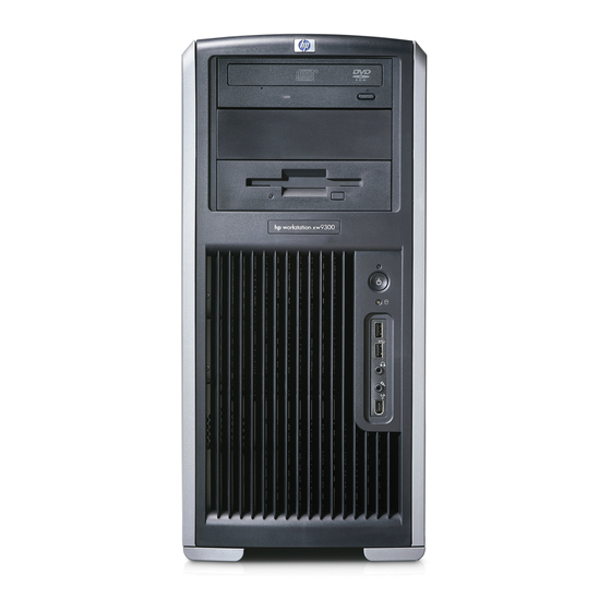
Page 19: Front Panel Components
Front Panel Components The following image shows a typical HP xw9300 Workstation. Drive configurations can vary. Table 1-2 Front Panel View Optical Drive Eject Button Power On Light Power Button Hard Drive Activity Light *An optical drive is a CD-ROM, CD-R/RW, DVD-ROM, DVD+R/RW, or CD-RW/DVD combo drive. -
Page 20: Rear Panel Components
Rear Panel Components Table 1-3 Rear Panel Components Universal Chassis Clamp Opening Access Panel Keys Padlock Loop Cable Lock Slot PS/2 Mouse Connector (green) RJ-45 Network Connector Audio Line-In Connector (light blue) Audio Line-Out Connector (lime) NOTE: To assist you in connecting your peripheral devices, the rear panel connectors are labeled and color-coded according to industry standards. -
Page 21: Serial Number And Coa Label Location
Serial Number and COA Label Location Each HP Workstation has two unique serial number labels. The serial number labels are located on the side panel of the unit and on the rear panel . You need this number when contacting customer service for assistance. -
Page 22: Product Specifications
Product Specifications The following table lists the physical dimensions of the HP xw9300 Workstation. Table 1-4 Physical Characteristics Weight (dependent on configuration) Tower Dimensions Rack Mount Dimensions (top cover and foot removed) Product Overview 19–24kg (42–54 lb) 455mm (17.9 inches) tall 210mm (8.3 inches) wide... -
Page 23: Power Supply And Cooling
Power Supply and Cooling This section contains the following information: • “Power Supply Specifications” on page 26 • “Power Consumption and Cooling” on page 27 • “System Fans and Airflow” on page 28 • “Resetting the Power Supply” on page 29 Power Supply and Cooling... -
Page 24: Power Output And Cooling
Power Output and Cooling The HP xw9300 Workstation power supply contains 9 outputs: • +3.3V—used with PCI, PCI-X, PCI-E, NVIDIA nForce Professional 2000 series MCPs, AMD8131, LS1030, IEEE 1394, Audio, Super I/O, on-board logic • +5V—used with storage (disk, optical, diskette), PCI, PCI-X, PCI-E, IEEE 1394, NVIDIA nForce Professional 2000 series MCPs, USB, input to on-board regulators (1.2V, 1.5V, 1.8V, and 2.5V), SCSI... - Page 25 Table 1-6 Power Supply and Cooling (Current) Current Minimum 12V-C V12N 5VSB WARNING! Do not exceed 136W of a 5V and 3.3V power combination. WARNING! Do not exceed 55A (660W) of 12V (CPU0/CPU1/A/B/C) power combination. WARNING! Do not exceed 700W of total continuous output power. Operating Continuous 12.5A...
-
Page 26: Power Supply Specifications
Power Supply Specifications The following table lists the power supply specifications. Table 1-7 Power Supply Specifications Full Ranging Input (No Line Select Switch) Active Power Factor Correction (APFC) (Input Current is nearly half of that of a non-APFC PS) Passive Power Factor Correction (PFC) Operating Voltage Range Rated Voltage Range Rated Line Frequency... -
Page 27: Power Consumption And Cooling
Power Consumption and Cooling The following table shows the power consumption for a typical configuration (based on primary power consumptions): • Two processors (2.4GHz Opteron) • 2GB memory (4x512MB) • Two hard drives (2xSATA 40GB) • DVD-ROM drive • PCI Express graphics card (FX1300) •... -
Page 28: System Fans And Airflow
System Fans and Airflow The workstation includes one rear system fan, one CPU heatsink for each processor (CPU), one power supply fan, plus a front system fan if two CPUs are installed. For airflow, this system includes a memory airflow duct and a CPU airflow duct, which is required if two CPUs are installed. Product Overview... -
Page 29: Resetting The Power Supply
Resetting the Power Supply If an overload triggers the power supply overload protection, all power is immediately cut. To reset the power supply unit: Disconnect the power cord. Determine what caused the overload and fix the problem. Reconnect the power cord and reboot the workstation. When you power down the workstation through the operating system, power consumption falls below the low power consumption but does not reach zero. -
Page 30: Environmental Specification
Environmental Specification The following table describes environmental specifications for the HP xw9300 Workstation. Table 1-9 Environmental Specifications Temperature (operating) Temperature (non-operating) Humidity (operating) Humidity (non-operating) Shock (operating) Shock (non-operating) Vibration (operating) Vibration (non-operating) Maximum Altitude (operating) Maximum Altitude (non-operating) Product Overview 40°... -
Page 31: Pci And Pci Express Slot Power Specifications
** Includes 75W maximum from the system board connector, and 75W maximum from the auxiliary graphics power connector. NOTE: If a graphics card requiring more than 75W is installed, HP recommends not using the slot immediately below the graphics card (for example, if PCI Express in slot 1, do not use slot 2). In addition to these slot power specifications, the overall power consumption of the system (including I/O cards, processors, memory, drives) must not exceed 700W. -
Page 32: Energy Star
Protection Agency (EPA) ENERGY STAR Computers Program. The EPA ENERGY STAR configuration does not imply endorsement by the EPA. As an ENERGY STAR Partner, HP has determined that products with the ENERGY STAR configuration meet the ENERGY STAR guidelines for energy efficiency. -
Page 33: Installing Or Restoring The Operating System
2 Installing or Restoring the Operating System This chapter describes the installation and restoration of the operating system. • “Installing the Operating System and Software” on page 34 • “Restoring the Operating System” on page 39 • “Protecting the Software” on page 40 •... -
Page 34: Installing The Operating System And Software
Go to the Help & Support Center installed on your system (on most factory-installed Windows XP • operating systems), click Start > Help & Support. Click the icon above HP Software & Drivers Download and review or select available updates. -
Page 35: Linux-Preinstalled Workstations
This is normal behavior. The boot process continues its execution after the screen returns. Restoring the Linux Operating System NOTE: To restore the Linux OS, the HP Driver CD and Red Hat box set are required. To get any new enhancements, download the latest HP Driver CD. NOTE: Linux does not support mixed drive types for a manufacturing preload. -
Page 36: Upgrading Device Drivers
Reboot the workstation. Follow the prompts to set up your system with the Red Hat First Boot utility. When prompted in First Boot to add additional CDs, insert the HP Driver CD into the CD-ROM tray of the workstation. Click Install next to “Additional CDs.”... -
Page 37: Linux-Enabled Workstations
Linux-Enabled Workstations Linux-enabled HP Workstations require the HP Installer Kit for Linux and the purchase of a Red Hat box set. The Installer Kit includes the HP CDs necessary to complete the installation of all versions of the Red Hat box set that have been verified to work on HP Workstation hardware. -
Page 38: Hp Software
HP Software The following HP software is installed the first time the HP Workstation is turned on: • Computer Setup (F10) Utilities and diagnostic features • HP Support Software including device drivers • HP Client Manager Software (available for download from http://www.hp.com/go/easydeploy) •... -
Page 39: Restoring The Operating System
Restoring the Operating System To restore the original Windows operating system and factory-installed software, insert the Restore Plus! CD that came with your HP Workstation. Carefully read and follow the instructions provided with the Restore Plus! CD. NOTE: If you restore your system using the Restore Plus! CD, some settings, such as your power management settings (such as the Energy Star®... -
Page 40: Protecting The Software
Protecting the Software To protect software from loss or damage, keep a backup copy of all system software, applications, and related files stored on the hard drive. See the operating system or backup utility documentation for instructions on making backup copies of data files. Installing or Restoring the Operating System... -
Page 41: Ordering Backup Software
Ordering Backup Software All software that shipped with the workstation, including the Restore Plus! CD, can be ordered from HP as a single set, or you can order the various software packages separately. NOTE: Before calling HP to order the software, be sure to have the serial number of the workstation available. - Page 42 Installing or Restoring the Operating System...
-
Page 43: System Management
3 System Management This section describes the various tools and utilities that allow for the system management of the workstation. • “Computer Setup (F10)” on page 44 • “Desktop Management” on page 54... -
Page 44: Computer Setup (F10)
Computer Setup (F10) This section contains the following information to help you use Computer Setup. • “BIOS ROM” on page 45 • “Using Computer Setup (F10)” on page 46 • “Computer Setup Menu” on page 47 The Computer Setup (F10) utilities enable you to: •... -
Page 45: Bios Rom
• Execute self-tests on specified SATA hard drives (when supported by the drive). BIOS ROM The Basic Input/Output System (BIOS) of the computer is a collection of machine language programs stored as firmware in read-only memory (ROM). The BIOS ROM includes such functions as POST, PCI device initialization, Plug 'n Play (PnP) support, power management activities, and the Setup utility. -
Page 46: Using Computer Setup (F10)
Using Computer Setup (F10) You can only open Computer Setup by turning on the workstation or restarting the system. To access the Computer Setup Utilities menu: Turn on or restart the workstation. Press the F10 key as soon as the monitor light turns green. f you do not press the F10 key at the appropriate time, you must restart the workstation and press NOTE: and hold the F10 key again to access the utility. -
Page 47: Computer Setup Menu
Computer Setup Menu NOTE: The following content is subject to change with new firmware releases, so your menu might be than the following table. Table 3-11 Computer Setup Menu Descriptions Heading Option Description File System Lists product name, processor type/speed/stepping, cache size (L1/L2), system ROM Information family and version, installed memory size, chassis serial number, integrated MAC for enabled or embedded NIC (if applicable), and asset tracking number. - Page 48 Table 3-11 Computer Setup Menu Descriptions (continued) Heading Option Storage Device Configuration System Management Description Lists all installed non-SCSI storage devices. SCSI storage drives will not be listed in Computer Setup (F10). SATA storage drives will not be listed in this menu. When a device is selected, detailed information and options are displayed.
- Page 49 Table 3-11 Computer Setup Menu Descriptions (continued) Heading Option Description Storage Removable Media Boot Options Enables/disables ability to boot the system from removable media. Removal Media Diskette Write Enables/disables ability to write data to removable media. BIOS IDE DMA Transfers Enable/disables the BIOS use of DMA for transfers.
- Page 50 Table 3-11 Computer Setup Menu Descriptions (continued) Heading Option Security Setup Password Power-On Password Smart Cover Allows you to disable cover removal sensor or to notify user if sensor has been Device Security Network Service Boot System IDs Data Execution Prevention System Management Description...
- Page 51 Table 3-11 Computer Setup Menu Descriptions (continued) Heading Option Description Advanced Boot Allows you to set: • POST Mode (QuickBoot, FullBoot, or FullBoot every 1–30 days). • POST Messages (enable/disable). F9 Prompt (enable/disable). Enabling this feature will display the text •...
- Page 52 Table 3-11 Computer Setup Menu Descriptions (continued) Heading Option Processors Chipset/ Memory Onboard Devices Device Options Thermal PCI VGA Configuration Slot 1 (PCI Express x 16) Slot 2 (PCI) Slot 3 (PCI Express x 16) Slot 4 (PCI-X 100) Slot 5 (PCI-X 100) System Management Description...
- Page 53 Table 3-11 Computer Setup Menu Descriptions (continued) Heading Option Description Slot 6 (PCI-X Configures the option ROM, latency timer, and PCI x4 function check**. 133) *Available on select models. **These options should be used by advanced users only. Computer Setup (F10)
-
Page 54: Desktop Management
Desktop Management HP Client Management Solutions (available for download from http://www.hp.com/go/easydeploy) provides standards-based solutions for managing and controlling workstations in a networked environment. This section summarizes the capabilities and features of the key components of desktop management: • “Initial Configuration and Deployment” on page 55 •... -
Page 55: Initial Configuration And Deployment
Using a disk cloning process to copy the contents from one hard drive to another. The best deployment method depends on your information technology environment and processes. The PC Deployment section of the HP Lifecycle Solutions Web site us/en/solutions.html) provides information to help you select the best deployment method. -
Page 56: Remote System Installation
The default boot order is a BIOS configuration setting that can be changed to always attempt to PXE boot. HP and Altiris have partnered to provide tools designed to make the task of corporate PC deployment and management easier and less time-consuming, ultimately lowering the total cost of ownership and making HP PCs the most manageable client PCs in the enterprise environment. -
Page 57: Software Updating And Management
Altiris Client Management Solutions HP and Altiris have partnered to provide comprehensive, tightly integrated systems management solutions to reduce the cost of owning HP client PCs. HP Client Manager Software is the foundation for additional Altiris Client Management Solutions that address: •... -
Page 58: System Software Manager
Subscriber’s Choice Subscriber’s Choice is a client-based service from HP. Based on your profile, HP will supply you with personalized product tips, feature articles, driver and support alerts/notifications, or both. Subscriber’s Choice Driver and Support Alerts/Notifications will deliver e-mails notifying you that the information you subscribed to in your profile is available for review and retrieval. -
Page 59: Rom Flash
The boot block jumper at E14 MUST NOT be installed during a ROM flash operation unless specified by HP. Normally, the boot block jumper is completely removed or installed only on E14 pin 2. Installing the boot block jumper enables changing the boot block and defeats the FailSafe Boot Block ROM protection. - Page 60 NOTE: Some models also support recovery from a ROMPaq CD. ISO ROMPaq images are included with selected models in the downloadable ROM softpaqs. When the boot block detects an invalid system ROM, the power LED blinks RED eight times, one every second, followed by a 2-second pause.
-
Page 61: Replicating The Setup
CAUTION: A setup configuration is model-specific. File system corruption might result if source and target workstations are not the same model. For example, do not copy the setup configuration from an HP xw4200 Workstation to an HP xw9300 Workstation. Select a setup configuration to copy. Turn off the workstation. -
Page 62: Dual-State Power Button
Do not use the power button to turn off the workstation unless the system is not responding; turning off the power without operating system interaction could cause damage to or loss of data on the hard drive. System Management 61). http://welcome.hp.com/support/files “Copying to a Single and enter the model number of the... -
Page 63: World Wide Web Site
HP has made the task of locating, accessing, evaluating, and installing the latest support software easier. You can download the software from http://www.hp.com/support. -
Page 64: Asset Tracking And Security
Asset tracking features incorporated into the workstation provide key asset tracking data that can be managed using HP Systems Insight Manager, HP Client Manager Software, or other system management applications. Seamless, automatic integration between asset tracking features and these products enables you to choose the management tool that is best suited to the environment and to leverage the investment in existing tools. -
Page 65: Password Security
NOTE: System Software Manager and HP Client Manager Software allow remote management of Setup Passwords and other BIOS settings in a networked environment. For more information, visit http://www.hp.com/go/easydeploy. - Page 66 NOTE: If you do not press the F10 key at the appropriate time, you must restart the workstation and press and hold the F10 key again to access the utility. If you are using a PS/2 keyboard, you might see a Keyboard Error message—disregard it. Select Security >...
- Page 67 (/) or alternate delimiter character, and your new password again as shown: current password/new password/new password NOTE: Type carefully. For security reasons, the characters you enter do not appear on the screen. Press Enter. The new password takes effect the next time you turn on the workstation. Desktop Management...
-
Page 68: Deleting A Power-On Or Setup Password
NOTE: See the “National Keyboard Delimiter Characters” on page 68 alternate delimiter characters. The power-on password and setup password can also be changed using the Security options in Computer Setup. Deleting a Power-On or Setup Password To delete a power-on or setup password: Turn on or restart the workstation. -
Page 69: Hood Sensor (Smart Cover Sensor)
When the workstation is restarted, the screen displays a message indicating that the workstation access panel has been removed. You must enter the setup password to continue. This option is only available if an administrator password is set. “Additional Password Security Desktop Management... -
Page 70: Cable Lock Provision (Optional)
Before exiting, click File > Save Changes and Exit. Cable Lock Provision (Optional) The rear panel of the chassis can accommodate a cable lock accessory that allows the workstation to be physically secured to a work area. Security Lock (Optional) Prevents entire system theft and discourages access panel removal. -
Page 71: Fault Notification And Recovery
Drive Protection System The DPS is a diagnostic tool built into the hard drives installed in select HP workstations. DPS is designed to help diagnose problems that might result in unwarranted hard drive replacement. When HP workstations are built, each installed hard drive is tested using DPS, and a permanent record of key information is written onto the drive. - Page 72 System Management...
-
Page 73: Removal And Replacement Procedures
4 Removal and Replacement Procedures This chapter describes removal and replacement procedures of most internal components. • “Service Considerations” on page 74 • “Pre-Disassembly Procedures” on page 79 • “System Board” on page 80 • “Removal and Replacement of Components” on page 82... -
Page 74: Service Considerations
Service Considerations The following sections discuss service considerations that should be reviewed and practiced before removing and replacing any system components. WARNING! When lifting or moving the workstation, do not use the front bezel as a handle or lifting point. Lifting the workstation from the front bezel or lifting it incorrectly can cause the unit to fall and harm the user and damage the workstation. -
Page 75: Electrostatic Discharge Information
Electrostatic Discharge Information A sudden discharge of static electricity from your finger or other conductor can destroy static-sensitive devices or microcircuitry. Often the spark is neither felt nor heard, but damage occurs. An electronic device exposed to electrostatic discharge (ESD) might not appear to be affected at all and can work perfectly throughout a normal cycle. -
Page 76: Personal Grounding Methods And Equipment
Personal Grounding Methods and Equipment Use the following equipment to prevent static electricity damage to equipment: • Wrist straps are flexible straps with a maximum of one-megohm ± 10% resistance in the ground cords. To provide a proper ground, wear the strap against bare skin. The ground cord must be connected and fit snugly into the banana plug connector on the grounding mat or workstation. -
Page 77: Tools And Software Requirements
If an incorrect screw is used during the reassembly process, it can damage the unit. HP strongly recommends that all screws removed during disassembly be kept with the removed part, then returned to their proper locations. -
Page 78: Lithium Coin Cell Battery
• Do not use excessive force when inserting a drive. • Avoid exposing a hard drive to liquids, temperature extremes, or products that have magnetic fields such as monitors or speakers. Lithium Coin Cell Battery The battery that comes with the workstation provides power to the real-time clock and has a minimum lifetime of about three years. -
Page 79: Pre-Disassembly Procedures
Pre-Disassembly Procedures Before servicing the workstation: Close any open software applications. Remove any diskette or compact disc from the workstation. Exit the operating system. Turn off the workstation and any peripheral devices that are connected to it. Remove/disengage any security devices that prohibit opening the workstation. CAUTION: Turn off the workstation before disconnecting any cables. -
Page 80: System Board
• “System Board Components” on page 80 • “System Board Architecture” on page 81 System Board Components The following illustration shows the system board connectors and sockets on the HP xw9300 Workstation. Table 4-18 System Board Components Memory module pairs... -
Page 81: System Board Architecture
System Board Architecture The following illustration shows the HP xw9300 Workstation block diagram. System Board... -
Page 82: Removal And Replacement Of Components
Removal and Replacement of Components This section discusses the procedures necessary to remove and install various hardware components on your workstation. Review the safety and precautions and the Safety and Regulatory Guide, before servicing or upgrading your system. Read all safety information and precautions. Locate and clear a suitable work area. -
Page 83: Disassembly Order
Disassembly Order Use the following table to determine the sequence in which to remove the major components. Pre-Disassembly (page Locks (page Access Panel (page Hood sensor Front Bezel Power Supply Memory Duct Front Fan Battery Hard Drive CPU Heatsink PCI Card Support (page (page Front Panel I/O Device Assembly... -
Page 84: Security Lock (Optional)
Security Lock (Optional) If a security lock is installed, remove it before servicing the unit. To remove the security lock, unlock it and slide it out of the padlock loop as shown in the following image. Cable Lock (Optional) If a cable lock is installed, remove it before servicing the unit. To remove the cable lock, unlock it and pull it out of the cable lock slot as shown in the following image. -
Page 85: Universal Chassis Clamp Lock
Universal Chassis Clamp Lock If a universal chassis clamp lock is installed, remove it before servicing the unit. To remove the lock: Unlock the device and remove the locking mechanism. Remove the screw attaching the lock to the chassis. Removal and Replacement of Components... -
Page 86: Access Panel
Access Panel Before accessing the internal components of the workstation, the access panel must be removed. To remove the access panel: WARNING! Before removing the workstation access panel, be sure that the workstation is turned off and that the power cord is disconnected from the electrical outlet. Disconnect power from the system If necessary, unlock the access panel Pull up... -
Page 87: Front Bezel
Front Bezel To remove the front bezel: Disconnect power from the system Lift up on the three tabs Rotate the front bezel away To replace the front bezel, reverse the previous steps. Bezel Blanks To remove the bezel blank: Disconnect power from the system bezel (page 87). -
Page 88: Hood Sensor
Hood Sensor To remove the hood sensor: Disconnect power from the system Unlatch the plastic snap that secures the cables inside the chassis. Disconnect the white 1x3 hood sensor connector from the in-line connector attached to the front panel harness. Slide the hood sensor forward, push the hood sensor down, and remove it from the chassis. -
Page 89: Front Panel I/O Device Assembly
Front Panel I/O Device Assembly To remove the front panel I/O device assembly: Disconnect power from the system front bezel (page 87). Unlatch the plastic snap that secures the cables inside the chassis and disconnect the front panel I/O device assembly cables from the system board. Remove the screws that hold the front panel I/O device assembly and bracket to the chassis remove the screws that hold the front panel I/O device assembly to the bracket Pull the front panel I/O device assembly out about two inches away from the chassis. -
Page 90: Power Button Assembly And System Speaker
Power Button Assembly and System Speaker The power button and the system speaker are part of the same assembly. To remove the power button: Disconnect power from the system bezel (page 87), and remove the front panel I/O device assembly Disconnect the power button assembly cable from the system board. -
Page 91: Power Supply
Power Supply To remove the power supply: Disconnect power from the system Disconnect the power supply from the system board. Disconnect the power supply cables from the optical drives, diskette drive, hard drives, and graphics cards (select models only). Remove the four screws Slide the power supply toward the front and lift up To replace the power supply, reverse the previous steps. -
Page 92: Memory Duct
Memory Duct To remove the memory duct: Disconnect power from the system Press in to unlatch the plastic clip Removal and Replacement Procedures (page 79) and remove the access panel and pull the duct away from the fan (page 86). -
Page 93: System Fan
System Fan To remove the system fan: Disconnect power from the system memory duct (page 92). Disconnect the fan plug Press in on the ribbed portion of the fan housing the chassis. To replace the system fan, reverse the previous steps. CAUTION: When replacing the system fan, be sure that the fan is situated so that the airflow direction arrow is pointing toward the back of the chassis. -
Page 94: Memory
Memory Memory Module Features • Contains 8 memory slots for DIMMS • Supports 512MB, 1GB, and 2GB pairs • Supports 1GB minimum configuration (2 x 512 DIMM) • Supports 16GB maximum configuration (8GB maximum on Windows and 16GB maximum on Linux) Supports dual-channel DIMMs •... - Page 95 To install a memory module: CAUTION: HP only ships DIMMs that are electrically and thermally compatible with this product. Because third-party DIMMs might not be electrically or thermally compatible, they are not supported by HP. NOTE: DIMMs and their sockets are keyed for proper installation. Be sure these guides line up when installing a DIMM.
- Page 96 Lower the DIMM straight down and be sure the socket levers secure the module into place. Removal and Replacement Procedures...
-
Page 97: Peripheral Component Interconnect (Pci) Slots
Peripheral Component Interconnect (PCI) Slots The section contains information on the following topics: • “PCI Slot Types” on page 97 • “PCI Card Support” on page 98 • “PCI Express” on page 99 • “PCI or PCI-X” on page 101 PCI Slot Types Table 4-19 PCI Slot Types... -
Page 98: Pci Card Support
PCI Card Support For added protection, some cards have PCI holders installed to prevent movement during shipping. To remove the card support: Disconnect power from the system For short or tall PCI cards, lift up on the holder arm the holder and rotate it To install card support: Disconnect power from the system For short or tall PCI cards, attach the lips of the support arm... -
Page 99: Pci Express
The PCI Express I/O slots can support other PCI Express cards with lesser bus bandwidth than what is physically defined for the slot. Use the following table to determine compatibility. NOTE: The HP xw9300 Workstation contains two PCI Express x16 slots. PCI Express slot three (see illustration “PCI Slot Types” on page 97 be used in a single-processor configuration. - Page 100 To remove a PCI Express card: Disconnect power from the system card support (page Lift the PCI levers Remove the power supply cable the card out of the chassis. Store the card in an anti-static bag. Install a PCI slot cover and close the PCI levers. If the PCI levers do not close, be sure all cards are properly seated and then try again.
-
Page 101: Pci Or Pci-X
PCI or PCI-X NOTE: The following illustration shows a PCI card being removed from a PCI slot. A PCI-X card is removed from a PCI-X slot. To remove a PCI or PCI-X card: Disconnect power from the system card support (page 98), if installed. - Page 102 NOTE: The following illustration shows a PCI card being installed in a PCI slot. A PCI-X card must be installed in a PCI-X slot. To install a PCI or PCI-X card: Disconnect power from the system card support (page Lift the PCI levers Remove the PCI slot cover Lower the PCI card into the chassis.
-
Page 103: Front Fan
Front Fan To remove the front fan: Disconnect power from the system Disconnect the header Unsnap the fan housing from the chassis Remove the fan from the fan housing by applying outward pressure on the fan housing while pushing the fan out of the housing. (page 79) and remove the access panel from the system board and thread it out of the card guide. - Page 104 To replace the front fan: Attach the fan to the fan housing as shown in the previous illustration. Lower the fan holder on the side of the fan faces the rear of the chassis. Plug the header Removal and Replacement Procedures into the chassis and snap it into place.
-
Page 105: Battery
Battery CAUTION: Before removing the battery, be sure your CMOS settings are backed up because all CMOS settings are lost when the battery is removed. To back up the CMOS settings, use Computer Setup and run the Save to Diskette option from the File menu. To remove the battery: Disconnect power from the system On the system board, press on the release tab of the battery holder... -
Page 106: Power Connections To Drives
Power Connections to Drives For help in identifying power cables, refer to the following information. Route or tie cables so that there is no possible way for them to interfere with the CPU heatsink fans. Removal and Replacement Procedures... -
Page 107: Optical Drive
Optical Drive To remove an optical drive: Disconnect power from the system front bezel (page 87). Disconnect the audio different than illustrated. NOTE: The audio cable is only required for Linux-based systems. Lift the green drivelock release lever If not installing another optical drives, replace the bezel blank. (page 79), remove the access panel , data... - Page 108 To replace an optical drive: Slide the optical drive into the bay until it stops. Lift the green drivelock release lever and push the drive in a few more inches, then release the lever and slide the drive completely into the bay until the drive is secured.
-
Page 109: Diskette Drive
Diskette Drive To remove a diskette drive: Disconnect power from the system front bezel (page 87). Disconnect the data While lifting the green drivelock release tab Remove the diskette drive by removing the two M3 screws diskette drive from the bracket. (page 79), remove the access panel and power... - Page 110 To replace a diskette drive: Slide the diskette drive into the bracket and secure with two M3 screws in the rearmost holes. Slide the optical drive into the bay until it stops. Lift the green drivelock release lever and push the drive in a few more inches, then release the lever and slide the drive completely into the bay until the drive is secured.
-
Page 111: Hard Disk Drive
Hard Disk Drive For more information on SATA hard drives and the SATA RAID configuration, see page 177. To remove a hard drive: Disconnect power from the system Disconnect the data Squeeze the green drivelock release tabs Installing a SCSI Hard Drive For more information on SCSI hard drives, see Before installing a SCSI hard drive on your system, you must give the hard drive a unique SCSI ID. - Page 112 Attach the rails to the hard drive by first inserting the hard drive rail assembly pins into one side of the hard drive screw holes. Next, gently flex open the opposite side of the hard drive rail assembly and insert the remaining pins into the holes in the hard drive. If installing the hard drive into bay 5, skip this step.
- Page 113 Connect the data cable to the internal SCSI connector on the system board. Removal and Replacement of Components 113...
-
Page 114: Installing An External Scsi Hard Drive
Installing an External SCSI Hard Drive You can add an external SCSI connector to the on-board SCSI controller. To install the external connector: Disconnect power from the system card support (page Disconnect the optical drive cable and the diskette drive cable, if installed, from the system board. Plug the data cable into the external SCSI port on the system board and route the cable under the PCI card guide as shown in the following illustration. -
Page 115: Installing A Sata Hard Drive
Installing a SATA Hard Drive For more information on SATA hard drives and the SATA RAID configuration, see page 177. To install one to four SATA drives: Disconnect power from the system Select a drive bay in which to install the drive. Squeeze the green tabs and slide the rails out of the empty bay. -
Page 116: Cpu Heatsink
CPU Heatsink The HP Workstation ships with more than one type of heatsink. Use the directions that best match your heatsink. CPU Heatsink A To remove the CPU heatsink: Turn on the workstation and enter Computer Setup (F10) mode for five minutes. - Page 117 Disconnect the CPU heatsink cable Rotate the latch lever away from the system board. WARNING! The latch lever is spring loaded and could cause injury. Use caution when rotating the latch lever away from the system board. On the opposite side where the lever is placed, press down on the metal clamp until the tab releases from the processor retention frame.
- Page 118 Rotate the CPU heatsink away metal clamp and rotating the entire CPU heatsink assembly away from the processor retention frame. When you have rotated the CPU heatsink assembly about 45 degrees, free the metal clamp under the black tension lever then lift the CPU heatsink up and away from the system board. 10.Use alcohol and a soft cloth to clean all of the thermal interface material residue from the CPU heatsink and processor.
- Page 119 Hook the metal latch over the plastic frame On the opposite side, clip the metal latch over the plastic frame. and rotate the CPU heatsink down Removal and Replacement of Components 119...
- Page 120 Rotate the latch lever down Connect the CPU heatsink cable to the white processor fan connector CAUTION: If the CPU heatsink cable does not reach the fan connector, you have installed the CPU heatsink backwards. Lower the CPU airflow duct over the CPU heatsinks until it snaps into place. NOTE: The CPU airflow duct is only required when two processors are installed.
-
Page 121: Cpu Heatsink B
CPU Heatsink B To remove the CPU heatsink: Turn on the workstation and enter Computer Setup (F10) mode for five minutes. This action warms the thermal interface material between the CPU heatsink and processor so that the thermal bond loosens and can more easily be broken. CAUTION: If you remove the CPU heatsink while the thermal pad is cold, you could lift the processor out of the socket, even if the socket is closed. - Page 122 Disconnect the CPU heatsink cable Hold down and press in release the clip from the processor retention frame on the system board. WARNING! The latch lever is spring loaded and could cause injury. Use caution when rotating the latch lever away from the system board. On the opposite side where the lever is placed, press down on the metal clamp until the tab releases from the processor retention frame.
- Page 123 Rotate the CPU heatsink away metal clamp and rotating the entire CPU heatsink assembly away from the processor retention frame. When you have rotated the CPU heatsink assembly about 45 degrees, free the metal clamp under the black tension lever then lift the CPU heatsink up and away from the system board. 10.Use alcohol and a soft cloth to clean all of the thermal interface material residue from the CPU heatsink and processor.
- Page 124 Hook the metal latch over the plastic frame On the opposite side, push down on the CPU heatsink to clip the other metal latch over the plastic frame. If necessary, use a flat-bladed screwdriver to snap the latch over the hook on the plastic frame. Removal and Replacement Procedures and rotate the CPU heatsink down...
- Page 125 Rotate the latch lever down until it snaps to the plastic frame. Connect the CPU heatsink cable to the white processor fan connector CAUTION: If the CPU heatsink cable does not reach the fan connector, you have installed the CPU heatsink backwards.
- Page 126 10.Lower the CPU airflow duct over the CPU heatsinks until it snaps into place. NOTE: The CPU airflow duct is only required when two processors are installed. NOTE: The CPU airflow duct more easily installs if the memory duct is temporarily removed first. 11.Install the front fan (page Removal and Replacement Procedures...
-
Page 127: Processor
Processor To remove the processor: Disconnect power from the system CPU heatsink (page 116). Raise the processor socket handle fully (the full swing angle of the lever is approximately 90 degrees). Pull the processor straight out of the socket. CAUTION: Handle the processor carefully. - Page 128 To replace the processor: Disconnect power from the system heatsink (page 116), and remove the processor Raise the processor socket handle fully (the full swing angle of the lever is approximately 90 degrees). CAUTION: Processor pins are delicate and bend easily. Use extreme care when placing the processor in the socket.
-
Page 129: System Board
System Board To remove the system board: Disconnect power from the system cards and graphics cards airflow duct (page 116), if installed, and remove the system fan assembly Disconnect all cabling from the system board. NOTE: Make note of the cable connections before disconnecting them from the system board. Refer to “Power Connections to Drives”... - Page 130 Removal and Replacement Procedures...
-
Page 131: System Diagnostics And Troubleshooting
• “E-Support” on page 132 • “Troubleshooting Checklist” on page 133 • “LED Color Definitions” on page 134 • “HP Insight Diagnostics Offline Edition” on page 135 • “Diagnostic Light Codes” on page 140 • “Troubleshooting Scenarios and Solutions” on page 142... -
Page 132: E-Support
To open HSC from your desktop, click Start > Help and Support. HSC contains four sections: • HP Product Information (requires Internet access)—Links to the HP Technical Support Web site for your product. You can access all related documentation, downloads and updates, tools, and more. •... -
Page 133: Troubleshooting Checklist
Troubleshooting Checklist Before running any of the diagnostic utilities, go through the following checklist to find possible solutions for workstation or software problems. • Are the workstation and monitor connected to a working electrical outlet? • Is the workstation turned on? •... -
Page 134: Led Color Definitions
LED Color Definitions An LED light exists on the front panel of your workstation. The following table describes what each color signifies. Table 5-21 LED Color Definitions LED State Solid Blinking Solid or Blinking None System Diagnostics and Troubleshooting LED Color System Status Green System is on. -
Page 135: Hp Insight Diagnostics Offline Edition
The information in each screen of the utility can be saved as an HTML file and stored on a diskette or USB HP Drive Key. Use HP Insight Diagnostics to determine if all the devices installed on the computer are recognized by the system and functioning properly. Running tests is optional but recommended after installing or connecting a new device. -
Page 136: Diagnostic Utility On Cd
Interactive and Unattended tests modes. Diagnostic Utility on CD HP Insight Diagnostics is available on the Documentation and Diagnostics CD that was shipped with your HP Workstation. To start the diagnostic utility on the Documentation and Diagnostics CD: Insert the Documentation and Diagnostics CD into the workstation. -
Page 137: Survey Tab
Users are provided the ability to select tests that do not require any user interaction through the Interactive and Unattended test modes. HP Insight Diagnostics Offline Edition 137... -
Page 138: Status Tab
To begin testing: Select the Test tab. On the left side of the tab, select the Type of Test to perform (Quick, Complete, or Custom). On the left side of the tab, select the Test Mode (Interactive or Unattended). Select the device to be tested from the drop-down list. Choose how you want the test to be executed, either Number of Loops or Total Test Time. -
Page 139: Saving And Printing Information In Hp Insight Diagnostics
Saving and Printing Information in HP Insight Diagnostics You can save the information displayed in the HP Insight Diagnostics Status and Log tabs to a diskette or a USB 2.0 HP Drive Key (64MB or higher). You cannot save to the hard drive. The system will automatically create an html file that has the same appearance as the information displayed on the screen. -
Page 140: Diagnostic Light Codes
Diagnostic Light Codes This sections provides an overview of the diagnostic lights that are related to your workstation. NOTE: The beeps are heard through the on-board piezo speaker and not the chassis speaker. The blinking lights and beeps repeat for five cycles. After that, only the blinking lights repeat. Table 5-22 Diagnostic Light Codes Chassis Indicator Lights... - Page 141 Beeps and blinks RED 5 times Pre-video memory error: Reseat memory modules. Replace memory modules one at a time to find the faulty module. Replace third-party modules with HP memory. Replace system board. Beeps and blinks RED 6 times Pre-video graphics card error: For systems with integrated graphics, replace the system board.
-
Page 142: Troubleshooting Scenarios And Solutions
Troubleshooting Scenarios and Solutions This section presents an extensive overview of various troubleshooting scenarios and includes possible solutions for each. Solving Minor Problems Table 5-23 Solving Minor Problems Problem Workstation appears locked up and does not turn off when the power button is pressed. - Page 143 Table 5-23 Solving Minor Problems Problem Cause Workstation powered off Processor thermal protection automatically and beeps activated: and blink RED twice. A fan might be blocked or not turning. The CPU heatsink is not properly attached to the processor. System does not power on System is unable to power on.
-
Page 144: Solving Power Supply Problems
Solving Power Supply Problems Testing Power Supply Before replacing the power supply, use the Built-In Self-Test (BIST) feature to learn if the power supply still works. To test the power supply: Disconnect all internal power supply cables. Plug in the AC power. •... - Page 145 Table 5-24 Power Supply Problems (continued) Problem Cause Power LED flashes RED once Power failure (power supply every two seconds. is overloaded). Solution Check if a device is causing the problem by removing ALL attached devices. Power on the system. If the system enters the POST, then power off and replace one device at a time and repeat this procedure until failure occurs.
-
Page 146: Solving Diskette Problems
Solving Diskette Problems Table 5-25 Diskette Problems Problem Diskette drive light stays on. Drive not found. Diskette drive cannot write to a diskette. System Diagnostics and Troubleshooting Cause Solution Diskette is damaged. In Windows, open Explorer and select File > Properties >... - Page 147 Table 5-25 Diskette Problems (continued) Problem Cause Cannot format diskette. Invalid media reported. A problem has occurred with a The directory structure is bad, disk transaction. or there is a problem with a file. Diskette drive cannot read Diskette is not formatted. a diskette.
-
Page 148: Solving Hard Drive Problems
Solving Hard Drive Problems Table 5-26 Hard Drive Problems Problem Hard drive error occurs. Disk transaction problem. Drive not found (identified). Nonsystem disk/NTLDR missing message. Workstation does not start. System Diagnostics and Troubleshooting Cause Solution Hard disk has bad sectors or Use a utility to locate and block usage of bad has failed. -
Page 149: Solving Display Problems
Solving Display Problems Table 5-27 Display Problems Problem Blank screen (no video). CAUTION: When attempting to resume from Standby mode, do not hold down the power button for more than four seconds. Otherwise, the workstation will shut down and you will lose your data. The display works properly during the POST but goes blank when the OS starts. - Page 150 Select the monitor’s Auto-Adjustment option in digital conversion circuits the monitor’s on-screen display menu. might be unable to correctly Go to the HP Support Web site and check for an interpret the output updated display driver. synchronization of the graphics card.
-
Page 151: Solving Audio Problems
Solving Audio Problems Table 5-28 Audio Problems Problem Sound does not come out of the speaker or headphones. CAUTION: When attempting to resume from Standby mode, do not hold down the power button for more than four seconds. Otherwise, the workstation will shut down and you will lose your data. Noise or no sound comes out of the speakers or headphones. - Page 152 Table 5-28 Audio Problems (continued) Problem NOTE: f you set digital as the Output Mode, the internal speaker and external analog speakers will no longer output audio until you switch back to an auto-sense or analog mode. If you set analog as the Output Mode, external digital speakers will not function until you change the output mode back to an auto-sense or digital mode.
-
Page 153: Solving Printer Problems
Solving Printer Problems Table 5-29 Printer Problems Problem Printer does not print. Printer does not turn on. Printer prints garbled information. Cause Solution Printer is not turned on and Turn the printer on and be sure it is online. online. Printer is out of paper. -
Page 154: Solving Keyboard And Mouse Problems
Solving Keyboard and Mouse Problems Table 5-30 Keyboard and Mouse Problems Problem Keyboard commands and typing are not recognized by the workstation. WARNING! When attempting to resume from Standby mode, do not hold down the power button for more than four seconds. Otherwise, the workstation will shut down and you will lose your data. Cursor will not move using the arrow keys on the keypad. -
Page 155: Solving Front Panel Component Problems
Solving Front Panel Component Problems If you are experiencing problems with one of the front panel ports, you might be able to try your device in the corresponding port on the back side of the computer. If this does not fix the problem, or you must use the front panel ports, continue troubleshooting. -
Page 156: Solving Hardware Installation Problems
(POST) and Error Messages” on page 165 determine possible causes. Memory is installed Reseat DIMMs. incorrectly or is bad. Replace DIMMs one at a time to isolate the faulty module. Replace third-party memory with HP memory. Replace the system board. “Power On Self Test... - Page 157 Table 5-32 Hardware Installation Problems (continued) Problem Cause Beeps and power LED flashes Video card is not seated RED six times. properly or is bad, or system board is bad. Solution For systems with a graphics card: Reseat the graphics card. If using PCI Express card with auxiliary power cable, be sure it is attached.
-
Page 158: Solving Network Problems
Solving Network Problems These guidelines do not discuss the process of debugging the network cabling. Table 5-33 Network Problems Problem Wake-on-LAN feature is not functioning. Network driver does not detect network controller. Network status link light does not turn on or it never flashes. The network status light should flash when there is network activity. - Page 159 Table 5-33 Network Problems (continued) Problem Cause Network controller stopped Network controller interrupt is working when an expansion shared with an expansion board was added to the board. workstation. The network controller requires drivers. The expansion board installed is a network card (NIC) and conflicts with the embedded NIC.
-
Page 160: Solving Memory Problems
Solving Memory Problems CAUTION: For those systems that support ECC memory, HP does not support mixing ECC and non-ECC memory. Otherwise, the system will not boot the operating system. Table 5-34 Memory Problems Problem System will not boot or does not function properly after installing additional memory modules. -
Page 161: Solving Processor Problems
Solving Processor Problems Table 5-35 Processor Problems Problem Poor performance is experienced. Power LED is RED and stays on. Processor is not seated Cause Solution Processor is hot. Be sure the airflow to the workstation is not blocked. Be sure the fans are connected and working properly (some fans only operate when needed). -
Page 162: Solving Cd-Rom And Dvd Problems
Solving CD-ROM and DVD Problems Table 5-36 CD-ROM and DVD Problems Problem System will not boot from CD- ROM or DVD drive. CD-ROM or DVD devices are not detected or driver is not loaded. Movie will not play in the DVD drive. -
Page 163: Solving Internet Access Problems
Solving Internet Access Problems Table 5-37 Internet Access Problems Problem Unable to connect to the Internet. Cannot automatically launch Internet programs. Cause Solution Internet Service Provider (ISP) Verify Internet settings or contact the ISP for account is not set up assistance. - Page 164 Table 5-37 Internet Access Problems (continued) Problem Internet takes too long to download Web sites. System Diagnostics and Troubleshooting Cause Solution Modem is not set up Verify that the correct modem speed and COM port properly. are selected. For Windows: Open the Control Panel.
-
Page 165: Power On Self Test (Post) And Error Messages
Power On Self Test (POST) and Error Messages POST is a series of diagnostic tests that runs automatically when the system is turned on. An audible, visual, or both message occurs if the POST encounters a problem. POST checks the following items to ensure that the workstation system is functioning properly: •... - Page 166 Windows utilities. Be sure memory modules are installed properly. If third-party memory has been added, test using HP only memory. Verify proper memory module type. Run Computer Setup (F10 Setup) or Windows utilities. Be sure that memory modules are installed correctly.
- Page 167 Table 5-38 POST Error Messages (continued) Screen Message Probable Cause 304—Keyboard or System Keyboard failure. Unit Error 501—Display Adapter Graphics display controller. Failure 510—Splash Screen image Splash Screen image has errors. corrupted 511—CPU0 or CPU1 Fan Fan is not connected or might have not detected malfunctioned.
- Page 168 Run the Drive Protection System test, if applicable. Apply firmware patch if applicable http:// (see www.hp.com/support). Back up contents and replace hard drive. Determine if hard drive is giving correct error message. Run the Drive Protection System test if applicable.
- Page 169 Table 5-38 POST Error Messages (continued) Screen Message Probable Cause 1782—Disk Controller Hard drive circuitry error. Failure 1790—Disk 0 Error The drive is not installed correctly or has failed. 1791—Disk 1 Error The drive is not installed correctly or has failed. 1792—Secondary Disk Hard drive circuitry error.
- Page 170 64-bit quadword of the memory array. Parity RAM failure. Run Computer Setup and Diagnostic utilities. Check that workstation air vents are not blocked and cooling fan is running. Verify processor speed selection. Replace the processor. Replace the system board. www.hp.com. http:// www.hp.com...
-
Page 171: A Scsi Devices
A SCSI Devices This appendix provides more information for setting up your SCSI hard drive. • “SCSI Guidelines” on page 172 • “Using SCSISelect with SCSI Devices” on page 173 • “SMART” on page 174 • “Jumpers” on page 175... -
Page 172: Scsi Guidelines
SCSI Guidelines When installing and operating SCSI devices, you must follow these guidelines: • A wide (68-pin) SCSI controller with two channels, one for internal devices and one for external devices. Five internal SCSI devices are supported. • If multiple SCSI devices are used, split the devices between Channels A and B for optimum performance. -
Page 173: Using Scsiselect With Scsi Devices
POST. The utility will only be present if an Adaptec SCSI card is present. • In POST Messages Disabled mode: When the HP logo screen appears, press any key to exit the logo screen. Immediately after exiting the logo screen, press Ctrl+A to access the SCSISelect utility. The utility will only be present if an Adaptec SCSI card is present. -
Page 174: Smart
SMART The SMART SCSI hard drives for HP workstations have built-in drive failure prediction that warns the user or the network administrator of an impending failure or crash of the hard drive. SMART drives track fault prediction and failure indication parameters, such as re-allocated sector count, spin retry count, and calibration retry count. -
Page 175: Jumpers
Jumpers All SCSI controllers require a unique SCSI ID (0–15) for each SCSI device installed. The controller identifies a SCSI device by its SCSI ID number rather than its location. Moving a SCSI device from one position to another on the SCSI chain does not affect communication between the controller and the device. - Page 176 SCSI Devices...
-
Page 177: Bsata Devices
SATA Devices This appendix provides additional information for setting up your SATA hard drives. • “SATA Guidelines” on page 178 • “SATA RAID Configurations” on page 179... -
Page 178: Sata Guidelines
SATA Guidelines NOTE: These systems support a mixed configuration of SCSI and SATA hard drives. The HP xw9300 Workstation does not support IDE hard drives. When installing and operating SATA devices: • Connect the SATA hard drive from the system board to the hard drive with the SATA cable (326965- 006). -
Page 179: Sata Raid Configurations
There are other RAID configurations, but they are not supported on an embedded SATA RAID. NOTE: For information on the integrated SATA RAID, visit and review the supplier’s documentation and HP User Manual for the Integrated NVIDIA SATA RAID Array for Microsoft® Windows® XP Professional. For information on supported SATA RAID configurations, visit http://www.hp.com/go/productbulletin. - Page 180 SATA Devices...
-
Page 181: C Connector Pins
C Connector Pins This appendix provides pin information for your system: • “Enhanced Keyboard” on page 182 • “Mouse” on page 182 • “Ethernet RJ-45” on page 182 • “Serial Interface” on page 183 • “USB” on page 183 • “IEEE 1394” on page 183 •... -
Page 182: Enhanced Keyboard
Enhanced Keyboard Keyboard Connector Mouse Mouse Connector Ethernet RJ-45 Ethernet Connector Connector Pins Signal Data Unused Ground +5 VDC Clock Unused Signal Data Unused Ground +5 VDC Clock Unused Signal (+) Transmit Data (-) Transmit Data (+) Receive Data Unused Unused (-) Receive Data Unused... -
Page 183: Serial Interface
Serial Interface Serial Connector USB Connector IEEE 1394 IEEE 1394 Connector Signal Carrier Detect Receive Data Transmit Data Data Terminal Ready Signal Ground Data Set Ready Request to Send Clear to Send Ring Indicator Signal +5 VDC - Data + Data Ground Signal power... -
Page 184: Microphone
Microphone Microphone Connector (1/8 inch) Headphone Headphone Connector (1/8 inch) Line-in Audio Line-in Audio Connector (1/8 inch) Line-out Audio Line-out Audio Connector (1/8 inch) Connector Pins Signal 1 (Tip) Audio 2 (Ring) Power 3 (Shield) Ground Signal 1 (Tip) Audio_Left 2 (Ring) Audio_Right 3 (Shield) -
Page 185: Ultra Scsi
Ultra SCSI Ultra SCSI connector Signal +DB12 +DB13 +DB14 +DB15 +DPB1 +DB0 +DB1 +DB2 +DB3 +DB4 +DB5 +DB6 +DB7 +DPB DIFFSENSE TERMPWR TERMPWR RESERVE +ATN +BSY +ACK +RST +MSG +SEL +C/D +REQ +I/O +DB8 +DB9 +DB10 +DB11 Signal -DB12 -DB13 -DB14 -DB15 -DPB1... -
Page 186: Sata
SATA SATA Connector Signal Data Cable Ground S-2* S-3* Ground S-5** S-6** Ground * S2 and S3 differential signal pair **S5 and S6 differential signal pair Connector Pins Signal Power Cable 3.3-V power 3.3-V power 3.3-V power Ground Ground Ground 5-V power Signal Power Cable... -
Page 187: Monitor (Vga)
Monitor (VGA) NOTE: Monitor connectors can vary depending on your configuration. VGA Connector Signal Red Analog Green Analog Blue Analog Monitor ID Ground Monitor (DVI) NOTE: Monitor connectors can vary depending on your configuration. DVI Connector Signal T.M.D.S DATA 2- T.M.D.S DATA 2+ T.M.D.S DATA 2/4 SHIELD T.M.D.S DATA 4-... -
Page 188: Ata/Atapi (Ide) Standard Drive Cable
T.M.D.S DATA 3+ +5V POWER ATA/ATAPI (IDE) Standard Drive Cable ATA/ATAPI (IDE) Connector Signal Reset Ground DD10 DD11 DD12 DD13 Connector Pins ANALOG HORZ SYNC ANALOG GROUND Signal DD14 DD15 Ground (Key) DMARQ Ground DIOW Ground DIOR Ground IORDY CSEL Signal DMAK Ground... -
Page 189: 24-Pin Power (Main)
24-Pin Power (Main) 24-Pin Main Power Connector +3.3 V +3.3 V +5 V +5 V 8-Pin Power (for Processors) 8-Pin Power (for CPUs) -12 V +5 Vaux +12 V-A PS_ON_L +12 V-A +3.3 V +3.3 V and +3.3V-Rsense Color with stripe with stripe... -
Page 190: 6-Pin Power (Auxiliary Pci Express)
6-Pin Power (Auxiliary PCI Express) NOTE: The 6-pin power (auxiliary PCI Express) is only required with high-powered graphics cards. 6-Pin Power (Auxiliary PCI Express) Connector Pins Color Signal +12V-C +12V-C +12V-C... -
Page 191: D System Board Designators
D System Board Designators This appendix lists the system board designators for this system. Table D-39 System Board Designators Designator MH1-8, MH10-11, MH14 J109 P101 Silkscreen PSWD SLOT2 PCI SLOT6 PCI-X 133MHz SLOT4 PCI-X 100MHz SLOT5 PCI-X 100MHz SCSI1 SCSI2 SLOT1 PCI-E X16 SLOT3 PCI-E X16 J109... - Page 192 Table D-39 System Board Designators Designator SW50 XMM1 XMM2 XMM3 XMM4 XMM5 XMM6 XMM7 XMM8 U150 System Board Designators Silkscreen FRNT AUD FRNT USB HD-LED SATA1 port 2 SATA1 port 3 SATA0 FRNT-P CPU1FAN CPU2FAN RCHFAN2 FCHFAN1 CLR CMOS XBT1 DIMM1A DIMM1B DIMM2A...
-
Page 193: E Power Cord Set Requirements
18 AWG, and the length of the cord must be between 6 feet (1.8 m) and 12 feet (3.6 m). If you have questions about the type of power cord to use, contact the HP authorized service provider. A power cord should be routed so that it is not likely to be walked on or pinched by items placed on it or against it. - Page 194 Power Cord Set Requirements...
-
Page 195: F Routine Care
Routine Care This appendix contains the additional information for caring for your system: • “General Cleaning Safety Precautions” on page 196 • “Maximizing the Airflow” on page 197 • “Cleaning the Workstation Case” on page 198 • “Cleaning the Keyboard” on page 199 •... -
Page 196: General Cleaning Safety Precautions
General Cleaning Safety Precautions • Never use solvents or flammable solutions to clean the workstation. • Never immerse any parts in water or cleaning solutions; apply any liquids to a clean cloth and then use the cloth on the component. •... -
Page 197: Maximizing The Airflow
Maximizing the Airflow Keep your workstation in an area where the airflow to the front and rear of the system is not obstructed. • If possible, keep the unit off of surfaces where dust can gather. • Keep the back of the unit at least 6 inches away from a wall or other obstruction. Keep the front of the unit clear of any obstruction that keeps air from entering the front of the system. -
Page 198: Cleaning The Workstation Case
Cleaning the Workstation Case Follow previously stated safety precautions before cleaning the workstation. To clean the workstation case: • To remove light stains or dirt, use plain water with a clean, lint-free cloth or swab. • For stronger stains, use a mild dish-washing liquid diluted with water. Rinse well by wiping it with a cloth or swab dampened with clear water. -
Page 199: Cleaning The Keyboard
Cleaning the Keyboard Follow all safety precautions stated earlier before cleaning the keyboard. CAUTION: Use safety glasses equipped with side shields before attempting to clean debris from under the keys. • Visible debris underneath or between the keys can be removed by vacuuming or shaking. •... -
Page 200: Cleaning The Monitor
Cleaning the Monitor Follow all safety precautions stated earlier before cleaning the monitor. To clean the monitor, wipe the monitor screen with a clean cloth moistened with water or with a towelette designed for cleaning monitors. Do not use sprays or aerosols directly on the screen; the liquid might seep into the housing and damage a component. -
Page 201: Cleaning The Mouse
Cleaning the Mouse Follow all safety precautions stated earlier before cleaning the mouse. To clean the mouse: • Clean the mouse ball by first removing the retaining plate and the ball from the housing. • Pull out any debris from the ball socket and wipe the ball with a clean, dry cloth before reassembly. Cleaning the Mouse 201... - Page 202 Routine Care...
-
Page 203: G Additional Password Security And Resetting Cmos
G Additional Password Security and Resetting CMOS This workstation supports security password features, which can be established through the Computer Setup Security menu. These features are: • setup password power-on password • When both passwords are set, the setup password can also be used in place of the power-on password as an override to log in to the workstation. -
Page 204: Resetting The Password Jumper
Resetting the Password Jumper To disable the power-on or setup password features and clear the power-on and setup passwords: Shut down the operating system and then turn off the workstation and any external devices. Disconnect the power cord of the workstation and any external devices from the power outlets. WARNING! To reduce the risk of personal injury from electrical shock and hot surfaces, be sure to disconnect the power cord from the wall outlet and allow the internal system components to cool before... -
Page 205: Clearing And Resetting The Cmos
Clearing and Resetting the CMOS The CMOS of the workstation stores password information and information about the workstation configuration. This section describes the steps to successfully clear and reset the CMOS. Using Computer Setup to Reset CMOS To reset CMOS using Computer Setup, access the Computer Setup Utilities menu. When the Computer Setup message appears in the lower-right corner of the screen, press the F10 key. -
Page 206: Using The Cmos Button
Using the CMOS Button CAUTION: Pushing the CMOS button resets CMOS values to factory defaults and erases any customized information including passwords, asset numbers, and special settings. It is important to back up the workstation CMOS settings before resetting them in case they are needed later. To back up the CMOS settings, use Computer Setup and run the Save to Diskette option from the File menu. -
Page 207: H Quick Troubleshooting Flows
H Quick Troubleshooting Flows This appendix presents some quick troubleshooting flowcharts for some common issues. NOTE: The flowcharts presented here are for general troubleshooting purposes only and they might not apply to your specific workstation. • “Initial Troubleshooting” on page 208 •... -
Page 208: Initial Troubleshooting
Initial Troubleshooting Quick Troubleshooting Flows... -
Page 209: No Power
No Power No Power, Part 1 No Power 209... -
Page 210: No Power, Part 2
No Power, Part 2 Quick Troubleshooting Flows... -
Page 211: No Power, Part 3
No Power, Part 3 No Power 211... -
Page 212: No Video
No Video No Video, Part 1 Quick Troubleshooting Flows... -
Page 213: No Video, Part 2
No Video, Part 2 No Video 213... -
Page 214: No Video, Part 3
No Video, Part 3 Quick Troubleshooting Flows... -
Page 215: Error Messages
Error Messages Error Messages, Part 1 Error Messages 215... -
Page 216: Error Messages, Part 2
Error Messages, Part 2 Quick Troubleshooting Flows... -
Page 217: Error Messages, Part 3
Error Messages, Part 3 Error Messages 217... -
Page 218: No Os Loading
No OS Loading Quick Troubleshooting Flows... -
Page 219: No Os Loading From Hard Drive
No OS Loading from Hard Drive No OS Loading from Hard Drive, Part 1 No OS Loading from Hard Drive 219... -
Page 220: No Os Loading From Hard Drive, Part 2
No OS Loading from Hard Drive, Part 2 Quick Troubleshooting Flows... -
Page 221: No Os Loading From Hard Drive, Part 3
No OS Loading from Hard Drive, Part 3 No OS Loading from Hard Drive 221... -
Page 222: No Os Loading From Diskette Drive
No OS Loading from Diskette Drive Quick Troubleshooting Flows... -
Page 223: No Os Loading From Cd-Rom Drive
No OS Loading from CD-ROM Drive No OS Loading from CD-ROM Drive 223... -
Page 224: No Os Loading From Network
No OS Loading from Network Quick Troubleshooting Flows... -
Page 225: Non-Functioning Device
Non-functioning Device Non-functioning Device 225... - Page 226 Quick Troubleshooting Flows...
-
Page 227: Index
Storage functions using utilities connectors front panel customizing software date and time display deleting password deployment tools, software desktop management device onboard device configuration diagnostic light codes diagnostic tool for hard drives DIMMs, installing and removing disassembly order disk, cloning... - Page 228 HP Client Management Solutions IDE connector pin assignments IEEE-1394 front panel location rear panel location information system initial configuration installing access panel battery bezel blanks DIMMs diskette drive front bezel front fan...
- Page 229 protecting hard drive rear panel components recovery, software remote setup Remote System Installation removable media boot removal and replacement removing access panel battery bezel blanks DIMMs diskette drive front bezel front fan front panel I/O device assembly hard drive heatsink hood cover Kensington cable lock memory...
- Page 230 Index...