Advertisement
Quick Links
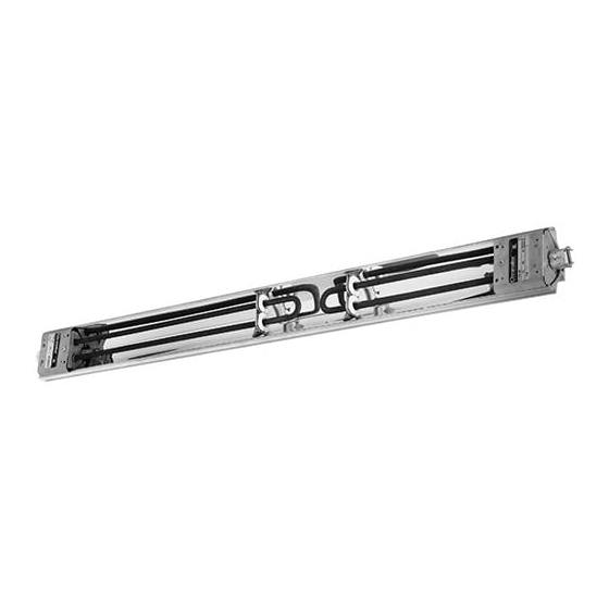
RENEWAL PARTS IDENTIFICATION
Type U-RAD Electric Radiant Heaters
The Safety Alert Symbol
risk of personal injury.
Please familiarize yourself with these instructions before
attempting to install or operate this Radiant Heater.
Before Installing
1. Open carton and remove heater at the place of installation.
Mounting clamps are in parts bag in carton.
2. Check nameplate volt and watt rating against your power supply
voltage and heating requirements of your installation. This
nameplate is located on one end of the heater.
The system designer is responsible for the safety of
this equipment and should install adequate back-up
controls and safety devices with their electric heat-
ing equipment. Where the consequences of failure
could result in personal injury or property damage,
back-up controls are essential.
Specifications Table –
Model
U-RAD-2
U-RAD-2V
U-RAD-3
U-RAD-3V
U-RAD-4V
U-RAD-4
U-RAD-5V
U-RAD-5
U-RAD-6V
U-RAD-6
U-RAD-7V
U-RAD-7
© 2010 Chromalox, Inc.
Chromalox
Installation, Operation
and
Double-Element U-RAD
!
is used to indicate a
Volts
kW
Overall
Single U-Shaped Element
120 or 240
800
12-3/4
208 or 275
120 or 240
1100
15-7/8
208 or 275
208 or 275
1800
23-13/16
240 or 480
208 or 275
2500
31-1/4
240 or 480
208 or 275
3000
37-1/4
240 or 480
208 or 275
3600
43-3/8
240 or 480
®
Conduit
Connector
Single-Element U-RAD
B
A
Model
U-RAD-22
U-RAD-22V
U-RAD-32
U-RAD-32V
U-RAD-33
U-RAD-33V
U-RAD-42V
U-RAD-42
U-RAD-43V
U-RAD-43
U-RAD-44V
U-RAD-44
U-RAD-52V
U-RAD-52
U-RAD-53V
U-RAD-53
U-RAD-54V
U-RAD-54
U-RAD-55V
U-RAD-55
U-RAD-62V
U-RAD-62
U-RAD-63V
U-RAD-63
Length (In.)
U-RAD-64V
Heated
U-RAD-64
U-RAD-65V
U-RAD-65
8-5/16
U-RAD-66V
U-RAD-66
11-7/16
U-RAD-72V
U-RAD-72
19-3/8
U-RAD-73V
U-RAD-73
26-13/16
U-RAD-74V
U-RAD-74
32-13/16
U-RAD-75V
U-RAD-75
38-15/16
U-RAD-76V
U-RAD-76
U-RAD-77V
U-RAD-77
SERVICE REFERENCE
4
DIVISION
SECTION
SALES
(Supersedes PG405-4)
REFERENCE
APRIL, 2005
DATE
B
A
Volts
kW
Two U-Shaped Elements
120 or 240
1600
208 or 275
120 or 240
1900
208 or 275
120 or 240
2200
208 or 275
208 or 275
2600
240
208 or 275
2900
240
208 or 275
3600
240
208 or 275
3300
240
208 or 275
3600
240
208 or 275
4300
240 or 480
208 or 275
5000
240 or 480
208 or 275
3800
240
208 or 275
4100
240
208 or 275
4800
240 or 480
208 or 275
5500
240 or 480
208 or 275
6000
240 or 480
208 or 275
4400
240
208 or 275
4700
240
208 or 275
5400
240 or 480
208 or 275
6100
240 or 480
208 or 275
6600
240 or 480
208 or 275
7200
240 or 480
U-RAD
PG405-5
161-048457-001
Length (In.)
Overall
Heated
25-1/2
16-5/8
28-5/8
19-3/4
31-3/4
22-7/8
36-9/16
27-11/16
39-11/16
30-13/16
47-9/16
38-11/16
44
35-1/8
47-1/8
38-1/4
55-1/16
46-3/16
62-7/16
53-9/16
50
41-1/8
53-1/8
44-1/4
61-1/16
52-3/16
68-1/2
59-5/8
74-1/2
65-5/8
56-1/8
47-1/4
59-1/4
50-3/8
67-1/8
58-1/4
74-1/2
65-5/8
80-5/8
71-3/4
86-3/4
77-7/8
Advertisement

Related Manuals for Chromalox U-RAD PG405-5


Summary of Contents for Chromalox U-RAD PG405-5
- Page 1 208 or 275 U-RAD-5 240 or 480 U-RAD-6V 208 or 275 U-RAD-6 240 or 480 U-RAD-7V 208 or 275 U-RAD-7 240 or 480 © 2010 Chromalox, Inc. ® Conduit Connector Single-Element U-RAD is used to indicate a Model U-RAD-22 U-RAD-22V U-RAD-32 U-RAD-32V...
-
Page 2: Installation
ELECTRIC SHOCK HAZARD. Disconnect all power before installing or servicing heater. Failure to do so could result in personal injury or property dam- age. Heater must be installed or serviced by a qual- ified person in accordance with the National Electrical Code, NFPA 70. - Page 3 ELECTRIC SHOCK HAZARD. Disconnect all power before installing or servicing heater. Failure to do so could result in personal injury or property dam- age. Heater must be installed or serviced by a qualified person in accordance with the National Electrical Code, NFPA 70. ELECTRIC SHOCK HAZARD.
-
Page 4: Operation
1. INPUT CONTROLLERS. These motor-driven cycling devices can be used to vary heater output capacity from 4 to 100%. They are usually connected in holding coil circuit of magnetic contactors. See Chromalox Radiant Heater Manual for further information regarding Input Controllers and Contactors. - Page 5 Model Volts Element UTU-4-208V 234-016383-003 UTU-3-208V 234-016383-002 UTU-4-240V 234-016383-003 U-RAD-43 2900 UTU-3-240V 234-016383-002 UTU-4-275V 234-016383-003 UTU-3-275V 234-016383-002 UTU-4(2)-208V U-RAD-44 3600 UTU-4(2)-240V 234-016383-003 (2) UTU-4(2)-275V UTU-5-208V 234-016383-004 UTU-2-208V 234-016383-001 UTU-5-240V 234-016383-004 U-RAD-52 3300 UTU-2-240V 234-016383-001 UTU-5-275V 234-016383-004 UTU-2-275V 234-016383-001 UTU-5-208V 234-016383-004 UTU-3-208V 234-016383-002 UTU-5-240V...
- Page 6 For element assembly part number, add prefix “R” to Element part number Ex: R UTU-6-208V. Model Volts Element Reflector UTU-2-120V UTU-2-208V U-RAD-2 234-016383-001 UTU-2-240V UTU-2-275V Please refer to the Chromalox limited warranty applicable to this product at http://www.chromalox.com/customer-service/policies/termsofsale.aspx. Model Volts U-RAD-3 U-RAD-4 U-RAD-5 U-RAD-6 U-RAD-7 U-RAD-22 U-RAD-32 U-RAD-33 Aluminum...