Advertisement
Quick Links
Chromalox
Note: Please familiarize yourself with these instructions before attempting
to install or connect this Radiant Heater.
Electric Radiant Heater
Before Installing
1. Open carton and remove heater at the place of installation.
Mounting clamps are in parts bag in carton.
2. Check nameplate volt and watt rating against your power sup-
ply voltage and heating requirements of your installation. This
nameplate is located on one end of the heater.
ELECTRIC SHOCK HAZARD. Disconnect all power
before installing or servicing heater. Failure to do
so could result in personal injury or property dam-
age. Heater must be installed by a qualified person
in accordance with the National Electrical Code,
NFPA 70.
1. Clamps — Heaters are mounted by means of the mounting
3
clamp and
/
" bolt assembly which is used as shown in Figure
8
2. Clamp assembly may be attached to heater by sliding over
end or by snapping over top of extruded frame section at any
point along its length (see Figure 3). For proper heater support,
the maximum distance between clamps must not exceed 48".
On extra-long heaters, more than two clamps are furnished.
2. Mounting Holes — When heaters are mounted adjacent to
each other in the same plane, note that distance between mount-
ing holes on framing to support heaters will be 3
When heaters are not in the same plane, i.e., set at an angle to
one another, distance between mounting holes in framing will
be either greater or less than 3
3. Framing — Where an extensive installation is being made, the
use of continuous slot metal framing manufactured by several
concerns will be of assistance in saving time and money. The
framing is reusable.
4. Reflector Spacer Sheets — Where heaters are not mounted
side by side (see Figure 4), reflector spacer sheets can be used
between heaters. These reflector spacer sheets and companion
reflectors consisting of an extruded aluminum housing with
reflector sheet and mounting clamps are available. Check factory.
5. Insulation — Where unusually high work temperatures are
encountered, it may be desirable to insulate backs of heaters
with high-temperature fibrous insulation. A suggested method
of accomplishing this is indicated in Figure 4.
6. Ventilation — Where solvents, water, etc. are being evaporat-
ed from work in process, it is necessary to provide substantial
quantities of ventilation air to carry away the resulting vapors.
© 2010 Chromalox, Inc.
Type S-RAD
MOUNTING
11
/
".
16
®
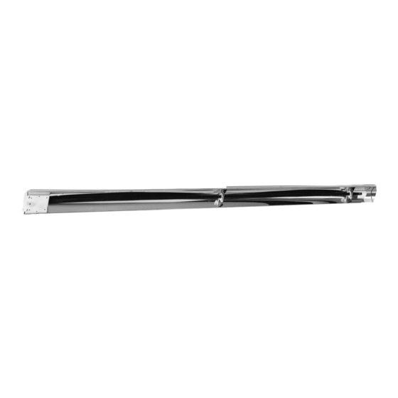
Figure 1 — Heater Parts and Dimensions
11
/
" minimum.
16
Figure 4
Hazard of Fire. In the case of solvents of an explo-
sive nature, ventilation air must be in sufficient vol-
ume to dilute the solvent vapor so that explosive
mixtures cannot occur. In order to comply with the
standards of safety required by the insurance com-
panies, ventilation protection and other facilities
must be in accordance with National Fire Protection
Association Bulletin No. 86, entitled "Standard for
Class A Ovens and Furnaces". This bulletin may be
obtained from the Association at 1 Batterymarch
Park, Quincy, MA 02269.
4
DIVISION
SECTION
SALES
(Supersedes PG422-1)
REFERENCE
SEPTEMBER, 2001
DATE
Specifications
Model
Volts
kW
S-RAD-2
120 or 240
0.95
S-RAD-2V
208 or 275
S-RAD-3
120 or 240
1.3
S-RAD-3V
208 or 275
S-RAD-4V
208 or 275
2.2
S-RAD-4
240 or 480
S-RAD-5V
208 or 275
3.0
S-RAD-5
240 or 480
S-RAD-6V
208 or 275
3.75
S-RAD-6
240 or 480
S-RAD-7V
208 or 275
4.4
S-RAD-7
240 or 480
2 / "
15 16
2 / "
3 8
11 16
3 / "
Figure 2
Mounting Frame
Insulation
Reflector
Spacer Sheet
RAD
PG422-2
161-058066-001
Length (In.)
Overall
Heated
24-3/8
16-1/2
30-5/8
22-3/4
46-5/8
38-5/8
61-3/8
53-3/8
73-3/4
65-3/4
85-3/4
77-3/4
Figure 3
Advertisement

Related Manuals for Chromalox S-RAD-2


Summary of Contents for Chromalox S-RAD-2
- Page 1 6. Ventilation — Where solvents, water, etc. are being evaporat- ed from work in process, it is necessary to provide substantial quantities of ventilation air to carry away the resulting vapors. © 2010 Chromalox, Inc. ® Figure 1 — Heater Parts and Dimensions ”...
- Page 2 2. SOLID STATE TROLLERS — For best non-contact control of radiant heat, a Series #6 Chromalox Thyristor Power Controller with manual potentiometer setting is recommended. Truly proportional output of from 0-100% can be easily dialed-in to suit the particular product or process requirements. The...
- Page 3 NOT use alkali cleaners since alkalies will dull reflector. Mild non-alkaline cleaners, such as used for scouring kitchen sinks, may be used. Reflectors are replaceable and may be purchased from Chromalox. RENEWAL PARTS IDENTIFICATION Part Number Terminal Cover ....... 080-013311-001 End Plate .
- Page 4 SRTU-530V-275 SRTU-530-480 SRTU-638V-208 S-RAD-6 3750 SRTU-638-240 SRTU-638V-275 SRTU-638-480 SRTU-744V-208 S-RAD-7 4400 SRTU-744-240 SRTU-744V-275 SRTU-744-480 Please refer to the Chromalox limited warranty applicable to this product at http://www.chromalox.com/customer-service/policies/termsofsale.aspx. Element P.N. 228-024788-001 228-024788-002 228-024788-003 228-024788-004 228-024788-005 228-024788-006 228-024788-007 228-024788-008 228-024788-009 228-024788-010 228-024788-011...