Advertisement
Quick Links
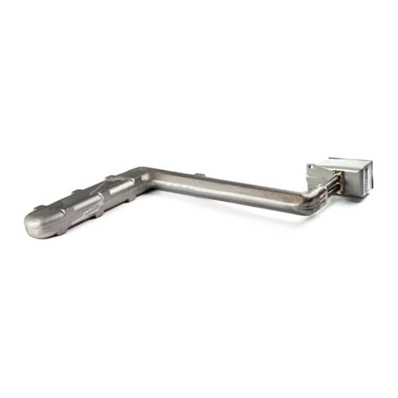
Cast Iron, Metal Melting, Immersion Heaters
Type CIT-1612 and CIT-1619
(Figure 1)
C
F
B
B
WARNING: Hazard of Shock. Disconnect all power
before installing, servicing or replacing heaters.
Chromalox Cast-Iron Immersion Heaters are generally used
for metal-melting applications such as solder, lead, tin, stereotype
metal, babbitt (with 4% or less copper) and other soft metals
where maximum working temperature is 950 ˚F.
Note: Not suitable for immersion in zinc or aluminum.
1. Heater Construction Characteristics —
A. High quality resistance wire held in place by compacted mag-
nesium oxide in heavy wall steel sheath cast in iron.
B. Large heat output at relatively low watt densities.
C. Excellent heat transfer.
1. Before installing the type CIT heater, inspect it for possible dam-
age which may have occurred during shipment. Also, check to
insure that the line voltage is the same as that stamped on the
nameplate.
2. CAUTION: Mount heater in the tank so that the liquid level will
always be above the effective heated portion of the heater. If the
heater is not properly submerged, it will overheat and damage the
heating elements and create a possible fire hazard due to exces-
sive sheath temperatures.
WARNING: When melting solids by direct immersion, a
surface vent should be provided to allow gases to
escape.
© 2010 Chromalox, Inc.
Chromalox
Installation
and
OPERATING INSTRUCTIONS
Maximum Melt Temperature — 950˚F
D
1" Conduit
A
Opening
E
Effective Heated Length
D
A
1" Conduit
Opening
E
Heated
Length
Type CIT-2219 and CIT-2319
(Figure 2)
®
Type CIT
Specifications
Model
Volts
CIT-218
240
CIT-1612
240
CIT-1619
240
CIT-2219
240
CIT-2319
240
Heated
Length
1-1/2"
E
F
B
5/8"
Tpye CIT-218
(Figure 3)
GENERAL
D. A rugged, cast iron terminal box protects the terminals against
spillage and abuse.
WARNING: Users should install adequate back-up
controls and safety devices with their electric
heating equipment. Where the consequences of
failure may be severe, back-up controls are essen-
t i a l , i n c l u d i n g G F C I ( G r o u n d F a u l t C i r c u i t
Interrupters). Although the safety of the installa-
tion is the responsibility of the user, Chromalox
will assist in identifying equipment options.
INSTALLATION
A. Over-the-Side
Models CIT-1612 and CIT-1619 (see Figure 1 - for use in flat
bottomed and straight-sided vessels); CIT-2219 and CIT-23 19
(See Figure 2 - for use in sloping vessels) are designed for over-
the-side installation.
1. To resist buoyancy of heater in heavy metals, securely mount
heater to metal crucible by clamping.
CAUTION: Do not support or suspend heater by the
tubular section adjacent to the terminal box as the
tubular section will be damaged by bending.
SERVICE REFERENCE
4
DIVISION
SECTION
SALES
(Supersedes PD412-4)
REFERENCE
MAY, 1999
DATE
Displacement
Volume
kW
(In
3
)
A
B
3
57
—
18
5
135
12-1/4
16
5
180
19-1/4
16
5
145
18-1/2 12-1/2
10
180
19
15-1/4
D
3-1/8"
C
1" Conduit
Opening
Gasket - For use with CIT-218
CIT
PD412-5
161-049179-001
Dimensions (In.)
C
D
E
F
4-5/8
2
17-3/8
2
2
9
10
3
2
6
17
3
—
6-1/2 14-1/2
—
—
9
15
—
2 Holes
9/16" Dia.
3-1/4"
4-5/8"
(Figure 4)
Advertisement

Related Manuals for Chromalox PD412-5


Summary of Contents for Chromalox PD412-5
-
Page 1: Operating Instructions
, i n c l u d i n g G F C I ( G r o u n d F a u l t C i r c u i t Interrupters). Although the safety of the installa- tion is the responsibility of the user, Chromalox will assist in identifying equipment options. - Page 2 2. The tank should be checked regularly for sediment around the heater as sediment can act as an insulator and shorten heater life. Please refer to the Chromalox limited warranty applicable to this product at http://www.chromalox.com/customer-service/policies/termsofsale.aspx. INSTALLATION 3.